


F R O N T AXLE D IFFER EN TIA L
3-7
13. Install flange, washer and nut. Torque nut to
specifications.
DIFFERENTIAL CASE
Preload and Adjustment
1. Place differential assembly (with pinion assembled)
into housing. Install bearing caps in their proper
position and tighten screws just enough to hold the
bearing cups in place.
2. Install dial indicator on carrier with indicator
button contacting back of ring gear (Fig. 7).
3. Place two screwdrivers between bearing cup and
housing on ring gear side of case, and pry ring gear
into mesh with pinion gear as far as it will go. Rock
ring gear to allow bearings to seat and gears to
mesh. With force still applied, set indicator to “0”.
4. Reposition screw drivers on opposite side of ring
gear and pry ring gear as far as it will go. Now take
an indicator reading. Repeat until the same reading
is obtained every time. This reading will be the
necessary amount of shims between the differential
case and differential bearing on the ring gear side.
Remove differential bearing from the ring gear side
and assemble proper amount of shims. Reassemble
bearing.
5. Remove the differential bearing from the opposite
side of ring gear. To determine the amount of
shims needed here, use the following method.
a. Subtract the size of shim pack just installed on
ring gear side of case from the reading obtained
and recorded in step 10 of Differential Case—
Reassembly.
b. To this figure, add an additional .015" shims to
compensate for preload and backlash.
Example: If reading in step 10 of Differential Case—
Reassembly was .085", and the shims installed on
ring gear side of case was .055", the correct amount
of shim will be .085" - .055" + .015" = .045".
6. Install shims as indicated in step 5, (which will give
the proper bearing preload and backlash) and
install side bearing.
Installation
1. Spread differential carrier, using spreader as shown
in Figure 1.
2. Install differential bearing cups in their correct
locations then install differential case into carrier.
3. Install differential bearing caps in the correct
location as indicated by marks made at disassem
bly. Install cap screws finger tight. Rotate
differential assembly and rap on case with a soft-
faced hammer to ensure proper seating of case in
carrier.
4. Remove spreader and torque cap bolts to
specifications.
5. Install dial indicator and check ring gear backlash
at four equally spaced points around the ring gear.
Backlash must be held to .004" to .009" and must
not vary more than .002" between positions
checked.
6. Whenever backlash is not within limits, differential
bearing shim pack should be corrected to bring
backlash within limits.
7. Check gear tooth contact, using red lead method, as
described in "Gear Tooth Contact Pattern Check".
8. After a successful pattern check, install housing
cover using a new gasket. Torque bolts to
specifications.
9. Install axle shafts and install axle assembly into
vehicle (See Service Manual).
10. Fill with recommended lubricant, lower vehicle to
floor and road test vehicle.
GEAR TOOTH C O NTACT PATTERN CHECK
Prior to final assembly of the differential, a Gear Tooth
Contact Pattern Check is necessary to verify the correct
relationship between ring gear and drive pinion. Gear
sets which are not positioned properly may be noisy, or
have short life, or both. With a pattern check, the most
desireable contact between ring gear and drive pinion
for low noise level and long life can be assured.
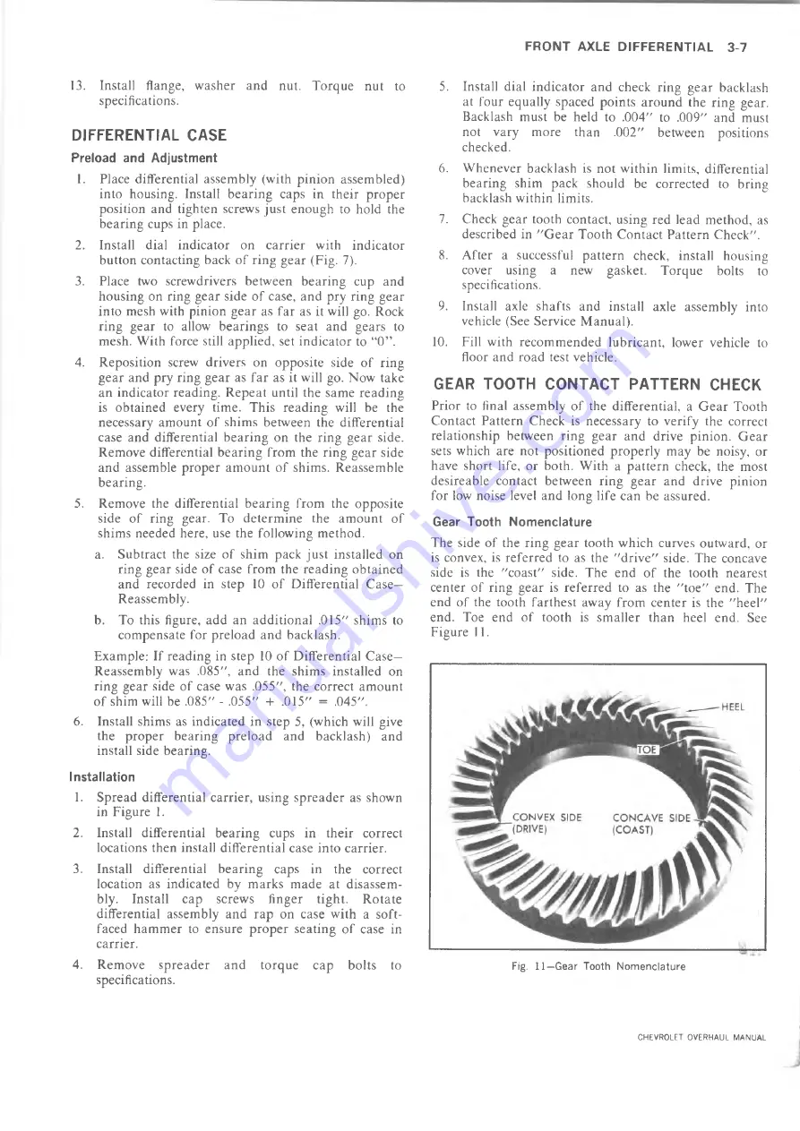
Gear Tooth Nomenclature
The side of the ring gear tooth which curves outward, or
is convex, is referred to as the "drive" side. The concave
side is the "coast" side. The end of the tooth nearest
center of ring gear is referred to as the "toe" end. The
end of the tooth farthest away from center is the "heel"
end. Toe end of tooth is smaller than heel end. See
Figure 11.
Fig. 11—Gear Tooth N o m en cla tu re
CHEVROLET OVERHAUL MANUAL
Summary of Contents for 10 series 1973
Page 1: ......
Page 3: ...r...
Page 5: ......
Page 21: ......
Page 31: ......
Page 34: ...REAR AXLE DIFFERENTIAL CARRIER 4 3 OVERHAUL MANUAL...
Page 85: ...4 54 REAR AXLE DIFFERENTIAL CARRIER OVERHAUL MANUAL...
Page 93: ...4 62 REAR AXLE DIFFERENTIAL CARRIER OVERHAUL MANUAL...
Page 103: ...V...
Page 141: ...I...
Page 144: ...ENGINE 6 3 OIL PRESSURE SENDING UNIT Fig 1 In Line Engine Lubrication OVERHAUL MANUAL...
Page 179: ......
Page 185: ...6M 6 CARBURETORS Fig M6 Monojet See Fig M7 for legend...
Page 219: ...L...
Page 289: ...7M 70 CLUTCHES AND MANUAL TRANSMISSIONS Fig 13F Transfer Case Exploded View OVERHAUL MANUAL...
Page 352: ...AUTOMATIC TRANSMISSION 7A 49 Fig 85M Planetary Gear Train Exploded View OVERHAUL MANUAL...
Page 363: ...7A 60 AUTOMATIC TRANSMISSION Fig IT S ide Cross Section Typical OVERHAUL MANUAL...
Page 457: ......
Page 459: ......
Page 522: ......


