


ELECTRICAL— BODY AND CHASSIS 12-19
Fig. 18— End Play Wear Washer Installation
NOTE:
Armature end play is controlled by end
play washers. See Figure 18 for proper assembly
of end play washers. Lubricate armature shaft
bushings with light machine oil.
Gear Box
1. Assemble gear box using reverse of disassembly
procedure.
NOTE:
Lubricate gear teeth with Delco Cam and
Ball Bearing lubricant or equivalent. Be sure
cover is properly located over dowel pins and be
sure to reinstall ground strap.
2. Place wiper in park position and install crank arm
on output shaft, rotate crank so alignment marks line
up with those on cover (fig. 19).
3. Replace retaining nut, place crank arm in vise,
tighten retaining nut.
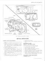
WINDSHIELD WASHER
GENERAL DESCRIPTION
The positive displacement washer pumps used on the
two-speed non-depressed park wipers (fig. 20) use a
pump mechanism consisting of a piston, piston spring
and valve arrangement driven by a 4 lobe cam, and
follower assembly (fig. 22). The cam is attached to
one shaft of the wiper motor output gear (fig. 21). Pro
gramming is accomplished electrically and mechanically
by a relay assembly and ratchet wheel arrangement.
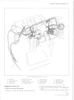
SERVICE OPERATIONS
from the wiper motor
Removal and Installation
Removal of the washer pump
consists of:
1. Disconnect battery ground cable.
2. Disconnect defroster hose and move to one side.
3. Remove ignition switch from instrument panel as
follows:
a. Remove lock cylinder by positioning switch in
"ACC” position and inserting a wire in the small
hole in the cylinder face. Puch in on wire to
depress plunger and continue to turn key counter
clockwise until lock cylinder can be removed.
b. Remove ignition switch bezel.
c. Push ignition switch through dash and let hand.
4. Disconnect electrical connector and hoses from
pump.
NOTE:
Mark washer hoses for correct reinstal
lation.
5. Remove two (2) pump mounting bolts.
NOTE:
Access upper right bolt through ignition
switch opening using suitable extension.
10-30 CHEVROLET TRUCK SERVICE MANUAL
Summary of Contents for 10 1971 Series
Page 1: ......
Page 96: ......
Page 100: ...10 30 CHEVROLET TRUCK SERVICE MANUAL Fig 4 10 30 Series Truck Frame FRAME 2 4 ...
Page 120: ......
Page 203: ...ENGINE 6 25 Fig 22L Engine Mounts 10 30 CHEVROLET TRUCK SERVICE MANUAL ...
Page 215: ...ENGINE 6 37 REAR M O U NT Fig 21V Engine Mounts 10 30 CHEVROLET TRUCK SERVICE MANUAL ...
Page 218: ......
Page 249: ......
Page 324: ......
Page 340: ......
Page 365: ...10 30 CHEVROLET TRUCK SERVICE MANUAL Fig 43 Power Steering Pump M ounting STEERING 9 25 ...
Page 368: ......
Page 386: ......
Page 390: ...ELECTRICAL BODY AND CHASSIS 12 4 10 30 CHEVROLET TRUCK SERVICE MANUAL ...
Page 391: ......
Page 428: ......
Page 432: ......
Page 449: ...SPECIFICATIONS 9 10 30 CHEVROLET TRUCK SERVICE MANUAL ...
Page 463: ......
Page 464: ......
Page 465: ......
Page 466: ......