


ELECTRICAL— BODY AND CHASSIS 12-9
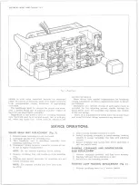
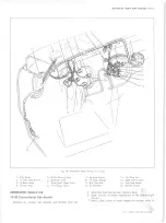
Fig. 9— Instrument Cluster Assembly - P-Models
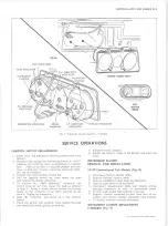
SERVICE OPERATIONS
IGN ITIO N SWITCH REPLACEMENT
1. Raise hood and disconnect battery ground cable from
battery.
2. Remove lock cylinder by positioning switch in “ ACC"
position and inserting wire in small hole in cylinder
face.
Push in on wire to depress plunger and con
tinue to turn key counter-clockwise until lock cylin
der can be removed.
3. Remove the metal ignition switch nut.
4. Pull the ignition switch out from under the dash
and remove the wiring connector.
5. To remove the “theft resistant" connector, the
switch must be out from under the dash as outlined
in Step 4. Using a screw driver unsnap the locking
tangs on the connector from their position on the
switch. Unplug the connector.
6. Snap the connector into place on a new ignition
switch.
7. Place the switch into position from behind the dash
and install the metal ignition switch nut.
8. Install the lock cylinder.
9. Install the battery cable to the battery and lower the
hood.
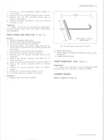
INSTRUMENT CLUSTER
REM OVAL A N D INSTALLATION
10-30 Conventional Cab Models (Fig. 8)
1. Disconnect battery ground cable.
2. Remove throttle control knob.
3. Remove windshield wiper knob and bezel nut.
4. Remove light switch rod and bezel.
5. Disconnect speedometer cable and chassis wiring
harness connector at rear of instrument panel.
6. Protect mast jacket with suitable covering.
7. Remove cluster retaining screws from face of as
sembly and remove cluster assembly from console.
8. To install, reverse removal procedure.
INSTRUMENT CLUSTER REPLACEMENT
P-MODELS (Fig. 9)
10-30 CHEVROLET TRUCK SERVICE MANUAL
Summary of Contents for 10 1971 Series
Page 1: ......
Page 96: ......
Page 100: ...10 30 CHEVROLET TRUCK SERVICE MANUAL Fig 4 10 30 Series Truck Frame FRAME 2 4 ...
Page 120: ......
Page 203: ...ENGINE 6 25 Fig 22L Engine Mounts 10 30 CHEVROLET TRUCK SERVICE MANUAL ...
Page 215: ...ENGINE 6 37 REAR M O U NT Fig 21V Engine Mounts 10 30 CHEVROLET TRUCK SERVICE MANUAL ...
Page 218: ......
Page 249: ......
Page 324: ......
Page 340: ......
Page 365: ...10 30 CHEVROLET TRUCK SERVICE MANUAL Fig 43 Power Steering Pump M ounting STEERING 9 25 ...
Page 368: ......
Page 386: ......
Page 390: ...ELECTRICAL BODY AND CHASSIS 12 4 10 30 CHEVROLET TRUCK SERVICE MANUAL ...
Page 391: ......
Page 428: ......
Page 432: ......
Page 449: ...SPECIFICATIONS 9 10 30 CHEVROLET TRUCK SERVICE MANUAL ...
Page 463: ......
Page 464: ......
Page 465: ......
Page 466: ......