


ENGINE COOLING 6K-3
4. Fill the cooling system with water to a level of about
3 inches below the top of the overflow pipe.
5. Cover the radiator and run the engine at moderate
speed until engine coolant temperature reaches 180
degrees.
6. Remove cover from radiator and continue to run the
engine for 20 minutes. Avoid boiling.
7. While the engine is still running, add the powder
portion (No. 2) of the cooling system cleaner and
continue to run the engine for 10 minutes.
8. At the end of this time, stop the engine, wait a few
minutes and then open the drain cocks. Also, remove
lower hose connection.
CAUTION:
Be careful not to scald your hands.
NOTE:
Dirt and bugs may be cleaned out of the
radiator air passages by blowing out with air
pressure from the back of the core. Do not bend
radiator fins.
Reverse Flushing
Reverse flushing should always be accomplished after
the system is thoroughly cleaned as outlined above.
Flushing is accomplished through the system in a direc
tion opposite to the normal flow. This action causes the
water to get behind the corrosion deposits and force
them out.
Radiator
1. Remove the radiator upper and lower hoses and re
place the radiator cap.
2. Attach a lead-away hose at the top of the radiator.
3. Attach a new piece of hose to the radiator outlet
connection and insert the flushing gun in this hose.
4. Connect the water hose of the flushing gun to a water
outlet and the air hose to an air line.
5. Turn on the water and when the radiator is full, turn
on the air in short blasts, allowing the radiator to fill
between blasts of air.
CAUTION:
Apply air gradually as a clogged
radiator will stand only a limited pressure.
6. Continue this flushing until the water from the lead-
away hose runs clear.
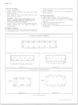
Radiator Cap
The radiator cap should be washed with clean water and
pressure checked at regular tune-up intervals. Inspect
rubber seal on cap for tears or cracks. Install radiator
cap on tester (fig. 4). If the pressure cap will not hold
pressure or does not release at the proper pressure,
replace the cap.
Cylinder Block and Cylinder Head
1. With the thermostat removed, attach a lead-away
hose to the water pump inlet and a length of new hose
to the water outlet connection at the top of the engine.
NOTE:
Disconnect the heater hose and cap
connections at engine when reverse flushing
engine.
2. Insert the flushing gun in the new hose.
3. Turn on the water and when the engine water jacket
is full, turn on the air in short blasts.
4. Continue this flushing until the water from the lead-
away hose runs clear.
Fig.
4—
Pressure Checking Radiator Cap
Heater Core
1. Remove water outlet hose from heater core pipe.
2. Remove inlet hose from engine connection.
3. Insert flushing gun and flush heater core. Care must
be taken when applying air pressure to prevent dam
age to the core.
Fan Belt Adjustment
1. Loosen bolts at Delcotron mounting.
2. Pull Delcotron away from engine until desired ten
sion reading is obtained with a strand tension gauge.
Refer to "Engine Tune Up Specifications".
3. Tighten all Delcotron bolts securely.
Thermostat
The thermostat consists of a restriction valve actuated
by a thermostatic element. This is mounted in the hous
ing at the cylinder head water outlet above the water
pump. Thermostats are designed to open and close at
predetermined temperatures and if not operating properly
should be removed and tested as follows:
Replacement
1. Remove radiator to water outlet hose.
2. Remove thermostat housing bolts and remove water
outlet and gasket from thermostat housing (fig. 5).
3. Inspect thermostat valve to make sure it is in good
condition.
4. Place thermostat in a 33% glycol solution 25° above
the temperature stamped on the thermostat valve.
5. Submerge the valve completely and agitate the water
thoroughly. Under this condition the valve should
open fully.
6. Remove the thermostat and place in a 33% glycol
solution 10° below temperature indicated on the
valve.
7. With valve completely submerged and water agitated
thoroughly, the valve should close completely.
8. If thermostat checks satisfactorily, re-install, using
a new housing gasket.
9. Refill cooling system.
Water Pump
Removal
1. Drain radiator and break loose the fan pulley bolts.
10-30 CHEVROLET TRUCK SERVICE MANUAL
Summary of Contents for 10 1971 Series
Page 1: ......
Page 96: ......
Page 100: ...10 30 CHEVROLET TRUCK SERVICE MANUAL Fig 4 10 30 Series Truck Frame FRAME 2 4 ...
Page 120: ......
Page 203: ...ENGINE 6 25 Fig 22L Engine Mounts 10 30 CHEVROLET TRUCK SERVICE MANUAL ...
Page 215: ...ENGINE 6 37 REAR M O U NT Fig 21V Engine Mounts 10 30 CHEVROLET TRUCK SERVICE MANUAL ...
Page 218: ......
Page 249: ......
Page 324: ......
Page 340: ......
Page 365: ...10 30 CHEVROLET TRUCK SERVICE MANUAL Fig 43 Power Steering Pump M ounting STEERING 9 25 ...
Page 368: ......
Page 386: ......
Page 390: ...ELECTRICAL BODY AND CHASSIS 12 4 10 30 CHEVROLET TRUCK SERVICE MANUAL ...
Page 391: ......
Page 428: ......
Page 432: ......
Page 449: ...SPECIFICATIONS 9 10 30 CHEVROLET TRUCK SERVICE MANUAL ...
Page 463: ......
Page 464: ......
Page 465: ......
Page 466: ......


