BRAKES 5-21
or could result in major repair expense. They
must be replaced with parts of the same part
numbers or with equivalent parts if replacement
becomes necessary. Do not use replacement
parts of lesser quality or substitute design.
Torque values must be used as specified during
reassembly to assure proper retention of these
parts.
3. Stop light switch should be adjusted if necessary, so
that electrical contact is made when pedal travel
measures .38” to .64” .
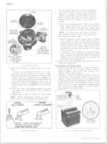
Fig. 42— Travel Switch Adjustment
PARKING BRAKE-REAR WHEEL
Systems (Figs. 43-44-45)
Refer to art Figures 43, 44 and 45 for routing of cables
and guides.
Brake Travel Warning Switch Adjustment
(Fig. 42)
Vehicles with frame mounted vacuum over hydraulic
boosters have an electrical switch that senses pedal
travel. This switch will illuminate the lamp on the
instrument panel whenever the brake pedal travel is in
excess of 5.10 inches.
Fig. 41 — Brake Pedal Free Movem ent
BRAKE P
BRACKET
A S S E M B L Y
A S S E M B L E D
LENGTH
5.94"
10-30 CHEVROLET TRUCK SERVICE MANUAL
Summary of Contents for 10 1971 Series
Page 1: ......
Page 96: ......
Page 100: ...10 30 CHEVROLET TRUCK SERVICE MANUAL Fig 4 10 30 Series Truck Frame FRAME 2 4 ...
Page 120: ......
Page 203: ...ENGINE 6 25 Fig 22L Engine Mounts 10 30 CHEVROLET TRUCK SERVICE MANUAL ...
Page 215: ...ENGINE 6 37 REAR M O U NT Fig 21V Engine Mounts 10 30 CHEVROLET TRUCK SERVICE MANUAL ...
Page 218: ......
Page 249: ......
Page 324: ......
Page 340: ......
Page 365: ...10 30 CHEVROLET TRUCK SERVICE MANUAL Fig 43 Power Steering Pump M ounting STEERING 9 25 ...
Page 368: ......
Page 386: ......
Page 390: ...ELECTRICAL BODY AND CHASSIS 12 4 10 30 CHEVROLET TRUCK SERVICE MANUAL ...
Page 391: ......
Page 428: ......
Page 432: ......
Page 449: ...SPECIFICATIONS 9 10 30 CHEVROLET TRUCK SERVICE MANUAL ...
Page 463: ......
Page 464: ......
Page 465: ......
Page 466: ......


