BRAKES 5-2
TO FRAME
BOOSTER
TO FRAME
BOOSTER
C- 30 WITH H -22 OPTION
P-30 WITH H-22 OPTION
C-K-P-20-30
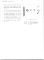
Fig. 1— M ain Cylinder - Typical
4, Refill the system.
5. Bleed the system.
BLEEDING HYDRAULIC SYSTEM
The hydraulic brake system must be bled whenever,
any line has been disconnected or air has in some way
entered the system. A "spongy" pedal feeling when the
brakes are applied may indicate presence of air in the
system. The system must be absolutely free of air at all
times. Bleeding of brake system may be performed by
one of two methods - either pressure or manual.
PRESSURE BLEEDING (Figs. 5 an d 6)
NOTE:
Pressure bleeding equipment must be of
the diaphragm type. That is, it must have a rub
ber diaphragm between the air supply and the
brake fluid to prevent air, moisture, oil and
other contaminates from entering the hydraulic
system.
1. Clean all dirt from top of main cylinder and remove
cylinder cover and rubber diaphragm.
2. Reduce fluid level in main cylinder until reservoirs
are approximately half full.
NOTE:
Make sure brake fluid in bleeder equip
ment is at operating level and that the equipment
is capable of exerting 20 to 30 lbs. hydraulic
pressure on the brake system.
3. Install brake bleeder adapter J-23518 (J-23339 for
frame mounted boosters) on main cylinder. Connect
hose from bleeder equipment to bleeder adapter and
open release valve on bleeder equipment.
NOTE:
The combination valve, located near the
main cylinder, must have the plunger depressed
while bleeding - use tool J-23709 as shown in
Figure 5.
4. Install brake bleeder wrench, Tool J-21472 on bleeder
valve at wheel cylinder and install one end of bleeder
hose on bleeder valve.
5. Pour a sufficient amount of brake fluid into a trans
parent container to ensure that end of bleeder hose
will remain sumerged during bleeding. Place the
loose end of bleeder hose into the container. Be sure
the hose end is submerged in the fluid.
10-30 CHEVROLET TRUCK SERVICE MANUAL
Summary of Contents for 10 1971 Series
Page 1: ......
Page 96: ......
Page 100: ...10 30 CHEVROLET TRUCK SERVICE MANUAL Fig 4 10 30 Series Truck Frame FRAME 2 4 ...
Page 120: ......
Page 203: ...ENGINE 6 25 Fig 22L Engine Mounts 10 30 CHEVROLET TRUCK SERVICE MANUAL ...
Page 215: ...ENGINE 6 37 REAR M O U NT Fig 21V Engine Mounts 10 30 CHEVROLET TRUCK SERVICE MANUAL ...
Page 218: ......
Page 249: ......
Page 324: ......
Page 340: ......
Page 365: ...10 30 CHEVROLET TRUCK SERVICE MANUAL Fig 43 Power Steering Pump M ounting STEERING 9 25 ...
Page 368: ......
Page 386: ......
Page 390: ...ELECTRICAL BODY AND CHASSIS 12 4 10 30 CHEVROLET TRUCK SERVICE MANUAL ...
Page 391: ......
Page 428: ......
Page 432: ......
Page 449: ...SPECIFICATIONS 9 10 30 CHEVROLET TRUCK SERVICE MANUAL ...
Page 463: ......
Page 464: ......
Page 465: ......
Page 466: ......


