HO NING
1. When honing the cylinders, follow the hone manu
facturer’s recommendations for use, cleaning, and
lubrication during honing. Use only clean, sharp
stones of the proper grade for the amount of mate
rial to be removed. Dull, dirty stones cut unevenly
and generate excessive heat. When using coarse
or medium grade stones, use care to leave suffi
c ie n t m etal so that all stone m arks may be
removed with the fine stones used for finishing to
provide proper clearance.
2. Occasionally, during the honing operation, the cyl
inder bore should be thoroughly cleaned and the
piston selected for the individual cylinder checked
for correct fit.
3. When honing to eliminate taper in the cylinder,
make full strokes of the hone in the cylinder. Also
check measurement at the top, middle, and bottom
of the bore repeatedly.
NOTICE: Handle the pistons with care and do
not attempt to force them through the cylin
der until the cylinder has been honed to the
correct size. The piston can be distorted
through careless handling.
4. When finish honing a cylinder bore to fit a piston,
move the hone up and down at a sufficient speed
to obtain very fine uniform surface finish marks in a
cross-hatch pattern at the specified angle.
• 2.2L: 45 degrees
• All others: 45 to 65 degrees
5. The finish marks should be clean but not sharp,
free from imbedded particles and torn or folded
metal.
6. By measuring the piston to be installed at the siz
ing point specified in the proper section, and
adding the average of the clearance specification,
the finish hone cylinder measurement can be deter
mined. It is important that both the block and piston
be measured at normal room temperature.
7. It is of the greatest importance that refinished cylin
der bores are trued up to have less than the speci
fied out-of-round or taper. Each bore must be final
honed to remove all stone or cutter marks and
provide a smooth surface.
8. Refer to “ Specifications” in the proper section for
piston to bore clearance tolerances.
9. After final honing and before the piston is checked
for fit, clean the bores with hot water and deter
gent. Scrub with a stiff bristle brush and rinse thor
oughly with hot water. It is essential that a good
cleaning operation be performed. If any of the
abrasive material is allowed to remain in the cylin
der bores, it will wear the new rings, cylinder bores,
and bearings lubricated by the contaminated oil.
After washing, the dry bore should be brushed
clean with a power-driven fiber brush.
10. P erm anently m ark the piston for the cylinder to
which it has been fitted.
11. Apply clean engine oil to each bore to prevent rust
ing.
PISTON AND CO NN ECTIN G
ROD ASSEM BLIES
DISASSEMBLY
Disassem ble (F igures 4, 5, and 6)
❖
Tools Required:
J 24086-B Piston Pin Remover and Installer
1. Piston rings. In most cases the rings should be dis
carded and replaced with new ones at assembly.
Summary of Contents for Light Duty Truck 1994 Series
Page 1: ......
Page 11: ...VIEW A p n n n j VIEW C F7554 Figure 10 Hydra Matic 4L60 E Transmission I D Location ...
Page 24: ...NOTES ...
Page 26: ... ...
Page 69: ...NOTES ...
Page 71: ...3 2 STEERING ...
Page 73: ......
Page 84: ......
Page 102: ...40 ...
Page 130: ...NOTES ...
Page 146: ...NOTES ...
Page 162: ...NOTES ...
Page 166: ...Figure 5 Removing the Pinion Flange Figure 6 Pressing the Drive Pinion from the Cage ...
Page 178: ...Figure 3 Spreading the Differential Case Figure 4 Removing the Differential ...
Page 190: ...NOTES ...
Page 202: ...NOTES ...
Page 206: ...F5785 ...
Page 212: ...B Button Moved Out of Bearing Bore F5791 ...
Page 228: ...NOTES ...
Page 232: ......
Page 234: ......
Page 236: ...Adjuster 63 Bolt 64 Lock Figure 10 Turning the Adjuster Plug K3 Models ...
Page 237: ...Figure 13 Removing the Pinion Seal 39 Bearing Cup Figure 16 Removing the Inner Bearing Cap ...
Page 261: ...F7475 ...
Page 267: ...B Button Moved Out of Bearing Bore F5791 ...
Page 294: ...NOTES ...
Page 300: ...NOTES ...
Page 318: ...NOTES ...
Page 322: ...SR207LN2 EDS ...
Page 324: ......
Page 326: ...OVERHEAD OILING AND RETURN MAIN OIL GALLERY N30005 6A2 J EDS ...
Page 368: ...103 153 127 V1200 ...
Page 370: ......
Page 372: ......
Page 374: ...F9375 Figure 7 Engine Lubrication Diagram Engines Without Balance Shaft ...
Page 376: ...Figure 9 Engine Lubrication Diagram Engines With Balance Shaft ...
Page 399: ...V2974 ...
Page 410: ......
Page 412: ...195 196 201 174 252 163 165 164 244 3706r3924 ...
Page 452: ......
Page 454: ...163 164 V1202 ...
Page 456: ...20 21x 302 210 4 0 41 2 5 2 5 1 2 51 4 2 e3 54 3 9 252 252 S 255 255 25 6 256 209 V1196 ...
Page 458: ...100 1 8 4 185 183 177 v 75 201 3706r1204 ...
Page 460: ......
Page 510: ......
Page 512: ...V2131 ...
Page 514: ...110 106 106 103 90 93 89 88 87 86 v 7 7 7 7 j A _ 111 f t 2 a a s 53 49 L 47 46 3706r4751 ...
Page 566: ...NOTES ...
Page 574: ...NOTES ...
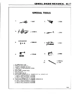
Page 618: ...SPECIAL TOOLS ...
Page 620: ...NOTES ...
Page 672: ......
Page 682: ......
Page 686: ......
Page 694: ...RH0213 4L60 E ...
Page 695: ...657 659 m i J 8092 H J 34196 4 3 34196 5 657 658 665 J 23907 J 7004 1 J 8092 RH0214 4L60 E ...
Page 696: ...J 8092 J 34196 4 33 31 J 8092 RH0215 4L60 E ...
Page 697: ...SPECIAL TOOLS ...
Page 698: ...SPECIAL TOOLS ...
Page 758: ...RH0194 4L80 E ...
Page 764: ......
Page 770: ...SPECIAL TOOLS ...
Page 771: ...SPECIAL TOOLS CONT ...
Page 772: ......
Page 775: ......
Page 776: ......
Page 785: ......
Page 804: ...NOTES ...
Page 806: ......
Page 808: ......
Page 822: ...3707r5079 ...
Page 840: ......
Page 848: ...NOTES ...
Page 852: ......
Page 860: ...F5435 ...
Page 866: ......
Page 878: ...F9167 ...
Page 882: ...16 FrontOutputShaft 18 DrivtQNr 19 DrivenGm t 20 DriveChain 22 FrontOutputBearing V2836 ...
Page 890: ...F9168 ...
Page 908: ......
Page 919: ......


