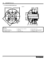
Chesterton TwinHybrid 4400H Installation, Operation And Rebuild Instructions Download Page 2

2

KEY

  1   –   Sleeve Assembly
  2   –   Shaft O-Ring
  3   –   Gasket
  4   –   Rotary O-Ring
  5   –  Rotary Seal Ring
  6   –  Adapter
  7   –   Rotary Cushion O-Ring
  8   –   Stationary Seal Ring
  9   –   Gland
10   –   Inter Gland O-Ring
11   –   OD Stationary O-Ring
12   –   ID Stationary O-Ring
13   –   Pusher Plate
14   –   Lock Ring
15   –   Centering Clip
16   –   Socket Head Cap Screw
17   –   Adjusting Screw
18   –   Screw O-Ring
19   –   Inboard Spring
20    –   Diaphragm
21   –   Actuator
22   –   Snap Ring
23    –   Seat O-Ring
24   –   Seat
25    –  Ball
26   –   Outboard Spring
27   –   Dog Point Set Screw
28   –   Cup Point Set Screw
29   –   Gland Screws
30   –   Spring
31   –   1/4" Pipe Plug
32   –   1/8" Pipe Plug
33   –   3/8" Pipe Plug
34   –   Cap Plug
35   –   Filter Disk
36   –   Retaining Clip
37   –   Support Gasket

These instructions are general in nature. It is assumed 

that the installer is familiar with seals and certainly with 

the requirements of their plant for the successful use of 

mechanical seals. If in doubt, get assistance from someone 

in the plant who is familiar with seals or delay the installation 

until a seal representative is available. All necessary auxiliary 

arrangements for successful operation (heating, cooling, 

flushing) as well as safety devices must be employed. These 

decisions are to be made by the user. The decision to use this 

seal or any other Chesterton seal in a particular service is the 

customer’s responsibility.

Transport and store seals in their original packaging. 

Mechanical seals contain components that may be subject to 

alteration and ageing. It is therefore important to observe the 

following conditions for storage:

Do not touch the mechanical seal for any reason while it is 

operating. Lockout or uncouple the driver prior to personal 

contact with the seal. Do not touch the mechanical seal  

while it is in contact with hot or cold fluids. Ensure that all  

the mechanical seal materials are compatible with the  

process fluid. This will prevent possible personal injury. 

•  Dust free environment
•  Moderately ventilated at room temperature
•  Avoid exposure to direct sunlight and heat.
•  For elastomers, storage conditions according to ISO 2230 

should be observed.

1.0 CAUTIONS

2.0 

TRANSPORT AND STORAGE

3.0   DESCRIPTION

3.1   Parts Identification


Figure 1

20

19

18

35

17

36

22

23

21

24

25

26

29

16

15

9

10

14

27

30

11

13

12

28, 31-34, 37 (not shown in this view)

3

6

4

1

5

2

7

8

Summary of Contents for TwinHybrid 4400H

Page 1: ...0 Transport and Storage 2 3 0 Description 2 3 1 Parts Identification 2 3 2 Operating Parameters 3 3 3 Standard Materials 3 3 4 Intended Use 3 3 5 Dimensional Data 4 5 4 0 Preparation for Installation...

Page 2: ...successful operation heating cooling flushing as well as safety devices must be employed These decisions are to be made by the user The decision to use this seal or any other Chesterton seal in a par...

Page 3: ...Materials Faces Carbon Stationary Seal Ring Sintered Silicon Carbide Rotary Seal Ring Elestomers FKM EPDM FEPM FFKM Metal Parts 316SS body Alloy C 276 springs and drive pins Hardened set screws stand...

Page 4: ...G Maximum Bolt Circle by Bolt Size H Slot Width T Shaft O Ring U Rotary Seal O Ring V Rotary Cushion O Ring W Stationary Seal O Ring outside diameter X Stationary Seal O Ring inside diameter Y Gland...

Page 5: ...25 4 000 2 06 2 125 2 99 44 122 136 026 136 126 141 10 1 25 4 000 2 29 2 125 3 11 44 124 138 028 138 128 143 11 1 375 4 360 2 45 2 125 3 24 3 36 57 126 140 029 140 130 145 11 OS 1 375 5 385 3 27 2 125...

Page 6: ...ironment 4 0 PREPARATION FOR INSTALLATION 4 1 Equipment 005 0 13 mm 1000 32 0 8 m Ra 002 0 05 mm 2 If possible attach a base dial indicator to the shaft and rotate both the indicator and shaft slowly...

Page 7: ...The cup point set screws installed in the lock ring are hardened steel and have metric threads for 25 mm 65 mm 1 000 thru 2 625 seals use a 3 mm hex key for 70 mm 90 mm 2 750 thru 3 625 seal use a 4 m...

Page 8: ...g connections are correctly fitted and fittings are leak free Fill and vent the equipment in accordance with the instructions of the equipment manufacturer Ensure barrier gas is connected and availabl...

Page 9: ...9 9 0 SEAL MAINTENANCE AND REBUILD cont 9 2 4400H TwinHybrid Gas Seal Rebuild Instructions 2 2a 10 9 13 4 5 3 7 5 4 1 1 2 12 6 8 9 30 7 11 B X B X 9a 37 9 13 M...

Page 10: ...REBUILD cont 9 2 4400H TwinHybrid Gas Seal Rebuild Instructions cont 13 11 8 14 27 28 28 27 15 16 12 20X B X B X 14 15 28 27 28 13a 20 3 36 33 35 21 17 19 18 X B X 19 6 29 F B X X 18 20 21 B X 17 23 2...

Page 11: ...11 9 0 SEAL MAINTENANCE AND REBUILD cont 9 2 4400H TwinHybrid Gas Seal Rebuild Instructions cont 23 32 31 34 X B X 24 X X B 22 20 psi 1 4 bar 30 100 psi 2 7 bar X X M B...

Page 12: ...phone 781 438 7000 Fax 978 469 6528 www chesterton com A W Chesterton Company 2014 All rights reserved Registered trademark owned and licensed by A W Chesterton Company in USA and other countries Ches...

Reviews: