background image

- 7 - 

6.8 

Tensioning  the  Band  Saw 

Blade


Danger! 

Too much tension can 

cause  the  band  saw 

blade  to  break.  Too  little  tension  can 

cause  the  driven  band  saw  wheel  to 

slip and the band saw blade to stop.


1.  Raise  upper  blade  guide  fully  (see 

"Operation"). 

2.  Checking the blade tension: 

-Check  tension  by  pushing  with  a 

finger,  halfway  between  table  and  upper 

blade guide, against the side of the blade 

(the  blade  should  flex  not  more  than  1-2 

mm).


Check  adjustment  at  the  blade  tension 

indicator.  The  scale  indicates  the  correct 

adjustment  in  dependence  on  the  band 

saw blade width.


3.  Correct  tension  if  necessary:  turning 

the 

setting 

knob 

(48)


counter-clockwise 

increases 

the 

blade  tension.

 Τ

urning  the  setting 

knob 

(48)

 counter-clockwise reduces 

the blade tension. 

6.9 Connection to Power Mains


Danger! High voltage


Operate the saw in only in 

a dry environment. 

Operate  the  saw  only  on  a  power 

source 

matching 

the 

following 

requirements  (see  also  "Technical 

Specifications"): 


mains 

voltage 

and 

system 

frequency  conform  to  the  voltage  and 

frequency  shown  on  the  machine's 

name plate; 

fuse  protection  by  a  residual 

current  operated  device  (RCD)  of 

30 mA sensitivity; 

outlets  properly  installed,  earthed 

and tested;


Note:


Check 

with 

your 

local 

Electricity  Board  or  your  electrician  if  in 

doubt  whether  your  house  service 

connection meets the requirements.


-        Make sure the power supply cable 

is  out  of  the  way,  so  that  it  does  not 

interfere  with  the  work  and  does  not 

pose  a  tripping  hazard  or  will  get 

damaged. 

Protect  the  power  supply  cable 

from  heat,  aggressive  liquids  and 

sharp edges. 

Use 

only 

rubber-insulated 

extension cables of sufficient lead 

cross  section  (3  x  1.5  mm

2

,  for 

machines with 3-phase motor: 5 x 

1.5 mm

2

).


Do  not  pull  on  the  power  supply 

cable to unplug.


1. 

When  the  saw  is  assembled  and  all 

safety  devices  are  installed,  connect 

it to the power supply. 

2. 

Start  saw  briefly  and  turn  OFF 

immediately again.


3. 

Check the band saw blade's direction 

of  rotation: 

in  the  cutting  area  it 

must run from the top downwards.


4. 

If  the  band  saw  blade  turns  in  the 

wrong  direction,  unplug  the  power 

supply cable at the saw.


5. 

Have 

the 

electrical 

connection 

changed 

by a qualified electrician

!


6.10


Connection to Power Mains


Assembly the cabinet stand 

check contents against the parts list. 

Locate  back  panel  and  right  &  left 

end  panels  onto  the  base  panel, 

secure using hex bolts and washers. 

Fasten  the  right  & left  end  panels  to 

the  back  panel,  secure  using  hex 

bolts and washers. 

Fasten  the  front  bracing  member  on 

to  the  right  &  left  end  panels 

assemble  using  hex  bolts  and 

washers.  Fasten    the  shelf  on  the 

right  &  left  end  panels  using 

remaining hex bolts and washers. 

Fit the door on to the end panel. 

With  assistance  lift  band  saw  and 

carefully  position  in  place  on  top  of 

work-stand. 

Fix  in  position  using  hex  bolts, 

through 

washer, 

cabinet 

stand, 

washer, hex  nut,  band  saw  and  lock 

Summary of Contents for W730

Page 1: ...14 BANDSAW OPERATING INSTRUCTIONS MODEL W730 Charnwood Cedar Court Walker Road Bardon Leicestershire LE67 1TU Tel 01530 516 926 Fax 01530 516 929 email sales charnwood net website www charnwood net ...

Page 2: ...aw blade 9 Saw table 10 Fence guide extrusion graduated 11 Lower housing door 12 Rip fence 13 On Off switch with emergency stop 1 2 3 4 5 6 7 8 9 10 11 12 13 14 15 17 16 20 18 19 21 22 23 REAR 14 Quick release lever for band saw blade 15 Setting knob for blade tracking adjustment 16 Setting knob for table turning adjustment 17 Motor 18 Machine base 19 Dust extraction port 20 Setting knob for drive...

Page 3: ...f purchase in case of a future warranty claim This machine must not be sold or lent to someone else without being accompanied by all machine documents supplied with it The manufacturer assumes no liability for any damage caused by neglect of these operating instructions Information in these instructions is marked as under Danger Risk of personal injury or environmental damage Risk of electric shoc...

Page 4: ...ver cut several workpieces at the same time and also no bundles containing several individual pieces Risk of personal injury if individual pieces are caught by the band saw blade uncontrolled When cutting round stock use a suitable jig to prevent the work piece from turning Entanglement hazard Ensure that no parts of the body or clothing can be caught and drawn in by rotating components no necktie...

Page 5: ...an be stored on the push stick holder provided at the band saw frame Replace push stick if damaged 4 Transport Set upper blade guide to its lowest position Remove projecting accessories When shipping use original packing if possible 5 Machine Details Note In this chapter the essential operating elements of the machine are introduced The proper use of the machine is described in chapter Operation R...

Page 6: ...h sides of the blade Mitre fence The mitre fence is inserted into the table slot from the table s front edge For mitre cuts the mitre fence turns to60 in both directions For 45 and 90 miters positive stops are provided To set a mitre angle loosen lock handle 38 by turning it counter clockwise Risk of injury When cutting with the mitre fence the lock handle must be firmly tightened 6 Initial Operat...

Page 7: ... Fasten the fence guide extrusion 58 with four each thumb screws and washers to the saw table 6 5 Installing the Rip Fence The rip fence can be used on both sides of the blade When the rip fence is moved from one side of the saw blade to the other the fence extrusion 44 needs to be reversed Place rip fence on the rip fence guide Tighten the lock lever 45 of the rip 6 6 Installing the Push Stick Ho...

Page 8: ...ments Make sure the power supply cable is out of the way so that it does not interfere with the work and does not pose a tripping hazard or will get damaged Protect the power supply cable from heat aggressive liquids and sharp edges Use only rubber insulated extension cables of sufficient lead cross section 3 x 1 5 mm2 for machines with 3 phase motor 5 x 1 5 mm2 Do not pull on the power supply cab...

Page 9: ...if individual pieces are caught by the saw blade uncontrolled Drawing in trapping hazard Do not wear loose clothing jewellery or gloves which may get caught and wound up by revolving machine parts Contain long hair with a hairnet Never cut stock to which ropes cords strings cables and wires are attached or which contain such materials Upper blade guide adjustment The height of the upper blade guid...

Page 10: ...t manufacturer can cause unforeseen damage Repair and maintenance work other than described in this section should only be carried out by qualified specialists 8 1 Changing the Band saw blade Danger Risk of injury even with the band saw blade at standstill Wear gloves when changing blades Use only suitable band saw blades see Technical specifications 1 Loosen the four thumb screws 50 and remove th...

Page 11: ...urn band saw wheel by hand in a clockwise direction several times to bring the guide bearings in correct position both guide bearings should just touch the band saw 4 Retigthen locking bolt 58 to lock the shaft 60 8 4 Aligning the Lower Blade Guide The lower blade guide consists of a thrust bearing supporting the band saw blade from the rear two guide bearings providing lateral These parts need to...

Page 12: ... in the housing remove cause for overheating let cool down for a few minutes then start again Band saw blade wanders off the line of cut or runs off the band saw wheels Band saw blade is not running dead center on the band saw wheels Correct tracking see Care and maintenance Band saw blade breaks Incorrect tension correct band saw blade tension see Initial operation Load too high reduce pressure a...

Page 13: ... 12 13 Electrical wiring diagram ...

Page 14: ... 86 M6 Hex nut 4 3 DJ350A01014 Front bracing member 2 12 GB889 86 M6 Hex Locking nut 2 4 GB97 1 85 6 Washer 21 13 GB70 85 M6 35 Bolt 1 5 GB5783 86 M6 16 Hex bolt 16 14 DJ350A04005 Gap pipe 1 6 DJ350A01013 Back panel 1 15 DJ350A04100 Low door 1 7 DJ350A01011 Right end panel 1 16 DJ350A01016 Shelf 1 8 DJ350A03002 Turn lock fasterner 1 17 GB818 85 M5 6 Screw 2 9 GB70 85 M6 16 Bolt 1 18 GB97 1 85 5 Wa...

Page 15: ...6 60 59 55 54 24 23 22 26 27 2 40 41 61 62 63 66 70 72 71 65 69 75 73 50 49 48 47 43 42 132 131 8 135 129 133 128 136 120 121 122 123 124 125 126 119 118 117 108 107 106 105 104 103 101 100 98 99 97 111 102 110 109 113 35 114 79 80 95 96 86 85 87 89 90 91 92 94 82 81 115 112 64 137 46 41 28 29 2 44 45 74 83 88 84 55 68 35 89 93 67 86 138 14 ...

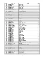
Page 16: ...4 31503018 Rack 1 25 DJ350A03001 Guide carrier extrusion 1 26 DJ350A03003 Pressure plate 1 27 DJ350A03004 pin 2 28 DJ31703113 gear 1 29 DJ350A03007 shaft for gear 1 30 31503014B Guide carrier system 1 31 GB845 85 ST4 8 22 Cross recessed pan head tapping screw 2 32 DJ315S03012A 1 adjusting nut 2 33 DJ315S03012A 2 guiding shanft 4 34 GB77 85 M8 30 Hex socket set columned head bolt 2 35 GB77 85 M6 6 ...

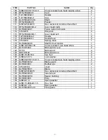
Page 17: ... 1 76 GB5783 86 M8 80 hex Bolt 1 77 DJ350A04003 Bearing bolt lower 1 78 31604006 Suctoin connector 1 79 DJ350A04009 Seat lower guide 1 80 DJ315B03024 Locking pin 1 81 DJ350A04007 Motor pulley 1 82 YYL8024E T Motor 1 83 DJ315D03001 Nut 1 84 TJ31502012 Hand wheel 1 85 DJ350A02003 Shaft for gear 1 86 TJ31503014 Gear 2 87 DJ315B02008 locking handle 1 88 DJ315B03036 Spacer bushing 1 89 DJ350A02002 Tabl...

Page 18: ...ng collar 1 119 DJ350A04006 Shaft for belt tension 1 120 GB818 85 M4 35 Cross recessed pan head screw 4 121 DJ31705002 Microswitch cover 2 122 HY50 Microswitch 2 123 RWLD0120 Microswitch box 2 124 GB6170 86 M4 hex Nut 4 125 GB862 1 87 3 Lock washer 4 126 GB845 85 ST3 5 9 5 Cross recessed pan head tapping screw 2 127 DJ350A04002 Blade guard 1 128 DJ35003003 Rubber tyre 2 129 31504010A J belt 1 130 ...

Reviews: