background image

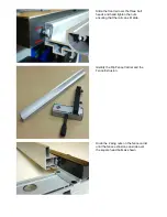
Blade Removal and Replacement 


Unplug the saw from the power source. 
 
Raise the blade to its maximum height and 
remove the saw guard from the riving knife. 
 
Remove the right hand table insert, using a 
4mm Hex key to remove the two screws. 


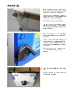
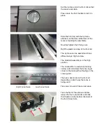
Use the special spanner supplied, lock the 
spindle by fitting it over the black locking 
washer.  
 
Then use a 13mm spanner to undo the 
blade locking bolt. 
 
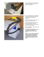
Remove the bolt, flat washer and locking 
washer. The blade can now be removed 
from the shaft.  
 
Reverse this procedure to fit the new blade. 


Adjusting Blade Alignment  


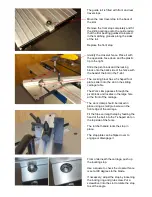
1) Disconnect the saw from the power supply and remove the two blue side panels from the main body.  
 
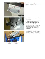
2) With a 4mm hex key loosen, but do not fully undo, the four Allen bolts located in the main cast iron table located 
just in front and behind the saw blade. There are four corresponding 10mm Nyloc nuts underneath the table.  


                           Allen Bolts                                                                     Nyloc Nuts  
 
3) By holding the motor it is then possible to adjust the alignment of the sawblade in the table slot.  
 
4) Measure the distance between the blade and the T slot in the table at both the front and rear of the blade, ensuring 
that both measurements are the same. Also, ensure that the blade will clear the table and insert when fully tilted.  
 

Summary of Contents for W619

Page 1: ...ION RIP FENCE OWNERS MANUAL MODEL W619PSF Charnwood Cedar Court Walker Road Hilltop Industrial Estate Bardon Hill Leicestershire LE67 1TU Tel 01530 516 926 Fax 01530 516 929 email sales charnwood net website www charnwood net ...

Page 2: ...ery which could get caught in moving parts Non slip footwear is recommended Wear protective hair covering to contain long hair 11 Always use safety glasses Normal spectacles only have impact resistant lenses They are not safety glasses 12 Do not over reach Keep proper footing and balance at all times 13 Maintain the machine in good condition Keep the machine clean for best and safest performance F...

Page 3: ...40v Blade diameter x bore 200mm x 30mm Blade rotation speed no load 4000 rpm Maximum depth of cut at 90 45 degrees 60mm 47mm Cutting width with table extension 730mm Mitre Guide T Slot Width 15 19mm Dust extractor hose connection 100mm Weight Nett Gross 80 100kg Rating Light Trade Rating Description Light Trade Suitable for professional woodworkers where the machine will not be in daily use Mid ra...

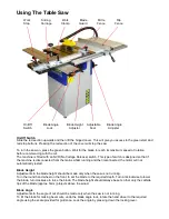
Page 4: ...iage Support Rail Fence Extrusion Tools Tables Guide Rail Hose Clips Allen Keys Crown Guard Push Stick Tilt Handwheel Feet Rip Fence Dust Hose Rip Fence Bracket Mitre Fence Hose Support Rail Supports Hold Down Clamp Clamp Fence Bracket Sliding Table with Rollers Length Stop Adjustable Fence Bracket ...

Page 5: ...ent rust This is easily removed with a soft cloth moistened with paraffin or WD40 Raise the saw blade by turning the fitted hand wheel at the front of the machine clockwise Fit the other hand wheel from the bag of components to the spindle on the right hand side of the saw Tighten the grub screw so that it engages with the flat on the spindle Turn the wheel clockwise until the blade is vertical if...

Page 6: ... it is difficult to slide on make sure that you have slackened the nuts sufficiently and rock the extrusion gently as you move it along You may need to reach round to the back of the brackets and unscrew the black adjusters a little if they are binding on the aluminium End Cap M6 Bolts Remove the end cap from the left hand end of the front rail Loosen the three M6 bolts in the front flange of the ...

Page 7: ...t heads and hand tighten the nuts ensuring that the rail can still slide Identify the Rip Fence Carrier and the Fence Extrusion Undo the 2 wing nuts on the fence carrier until the fence extrusion can slide over the square head bolts as shown ...

Page 8: ...to the front rail The rip fence can be assembled in two different ways High and Low The standard assembly is in the High position The low position is used when making narrow cuts and allows the fence to get closer to the blade without fouling on the crown guard There is a dual scale on the front rail depending on which way the fence is being used Take care to read off the correct scale Take the fi...

Page 9: ...to place Fit the dust collection hose to the saw guard and the spigot on the rear extraction point Secure in place with the two hose clamps provided Clip the hose into the support arm to hold it clear of the table It is strongly recommended you use a dust extractor at all times by connecting a hose to the 100mm outlet Failure to use an extractor will require stopping the machine regularly to clean...

Page 10: ...ing bolts Position the sliding carriage guide rail so that the back edge of the rail is level with the back side of the rear support rail Ensure the guide rail is parallel to the saw blade before tightening the eight nuts Before fitting the sliding carriage it should be noted that the two outboard bearing wheels are mounted on eccentric holes Should it ever be necessary any wear to the carriage ca...

Page 11: ...foot plate slide it into the slot in the sliding carriage table The Work clamp passes through the pivot block and locates in the large hole at the front of the carriage The work clamp should be locked in place using a small grub screw in the front edge of the carriage Fit the flip over length stop by feeding the head of the bolt into the T shaped slot on the top side of the fence The ratchet handl...

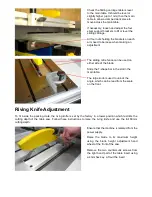
Page 12: ...e bar in the slot in the main table The large knob is used to unlock the angle which can be read from the scale on the front Riving Knife Adjustment To fit inside the packing crate the riving knife is set by the factory in a lower position which restricts the cutting depth of the table saw Follow these instructions to raise the riving knife and use the full 60mm cutting depth Ensure that the machi...

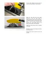
Page 13: ...ed just above the top of the saw blade If necessary adjust the riving knife so that there is an even gap of around 5mm between the curved leading edge of the knife and the radius of the saw blade Adjust the crown guard so that it is parallel to the table Re tighten the two bolts Replace the table insert and screws The saw can now be used to cut at full capacity ...

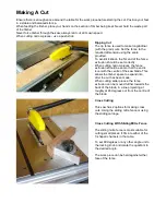
Page 14: ...is designed so that if the machine is disconnected from the mains whilst running and then reconnected the motor will not automatically restart Blade Height Adjustments to the blade height should be made only when the saw is not running Turn the round hand wheel on the front to set the blade to the required depth Turn anticlockwise to lower the blade turn clockwise to raise the blade The blade heig...

Page 15: ...cutting narrow pieces the fence extrusion should be set so that the end is level with the centre of the saw blade This allows the timber space to expand into after the cut has been made When cutting wider pieces the fence extrusion can be moved further towards the back of the blade in a line projecting at roughly at 45 degrees out from the centre of the blade Cross Cutting This saw has 2 options f...

Page 16: ...nce so that the plastic tip is just clear of the blade Load the wood onto the carriage and screw down the work clamp to secure it Press the start button and push the wood through the saw blade An alternative configuration is available for the sliding carriage The fence can be assembled onto the back edge of the table in a mirror image of the standard configuration The work piece is loaded against ...

Page 17: ...new blade Adjusting Blade Alignment 1 Disconnect the saw from the power supply and remove the two blue side panels from the main body 2 With a 4mm hex key loosen but do not fully undo the four Allen bolts located in the main cast iron table located just in front and behind the saw blade There are four corresponding 10mm Nyloc nuts underneath the table Allen Bolts Nyloc Nuts 3 By holding the motor ...

Page 18: ...s from the base of the saw The adjustment handwheel will need to be removed but should then be replaced and secured on the threaded shaft 90 Degree Stop With 4mm Allen Key loosen the limiting collar fitted to the threaded shaft Using a suitable square accurately adjust the blade to 90 degrees Ensure that the square is positioned between teeth and is flat against the plate of the blade Hold the lim...

Page 19: ...llen Key loosen the 45 degree limiting collar situated at the opposite end of the threaded shaft Using a mitre square adjust the blade accurately to 45 degrees Hold the limiting collar firmly against the Threaded Nut and retighten the grub screw Replace the blue covers and handwheel ...

Page 20: ... blunt or damaged Examine the blade If any Tungsten tips are missing or broken the blade should be replaced If the tips are blunt the saw blade may to be professionally sharpened Saw stalls Feed rate too high Slow down Wood binds on rear of saw blade Rip fence is not parallel to blade Bring the fence up to the blade and re align the fence so it is parallel by adjusting the 2 small set screws locat...

Page 21: ...ntial requirements of the directive Signed Dated 20 08 2013 Location Leicestershire Richard Cook Director Please dispose of packaging for the product in a responsible manner It is suitable for recycling Help to protect the environment take the packaging to the local amenity tip and place into the appropriate recycling bin Only for EU countries Do not dispose of electric tools together with househo...

Page 22: ...CHARNWOOD W619 PARTS DIAGRAM A ...

Page 23: ... 16mm A43 Hex Nut M6 A44 Outstretched Arm A45 Angle Iron A46 Large Washer M6 A47 Box Assembly A48 Sliding Table Assembly A49 Guide Rail A50 Hex Nut M8 A51 Washer M8 A52 Screw M8 x 10mm A53 Locking Handle A54 Pin 3 x 12mm A55 Locking Shaft A56 Large Washer M8 A57 Space Bush A58 Screw M4 x 6mm A59 Tooth Washer M4 A60 Pointer A61 Saw Assembly A62 Large Washer M8 A63 Locking Nut M8 A64 Hex Nut M8 A65 ...

Page 24: ...Bolt B10 Set Screw M8 x 10mm B11 Eccentric Nut B12 CSK Screw M6 x 35mm B13 Thumb Screw B14 Washer M6 B15 Connecting Block B16 Hex Nut M6 B17 Washer M6 B18 Plastic Tip B19 Hex Bolt M6 x 25mm B20 Angle Fence B21 C Ring M12 B22 Press Handle B23 Square Nut B24 Angle Ruler B25 Sliding Table B26 Locking Nut M10 B27 Washer M10 B28 Length Stop Plate B29 Ratchet Handle B30 Washer M6 B31 Stop Block B32 Hex ...

Page 25: ...Plate C18 Large Washer M6 C19 Hex Bolt M6 x 16mm C20 Hex Bolt M8 x 16mm C21 Washer M8 C22 Large Washer M6 C23 Locking Nut M6 C24 Washer M12 C25 Hex Thin nut M12 C26 Turning Pole C27 Motor Rack C28 C Ring M19 C29 Key 6 x 25mm C30 Motor 240v C31 Hex Bolt M8 x 25mm C32 Washer M8 C33 Clamp Plate C34 Riving Knife C35 Bolt M6 x 30mm C36 Bolt M6 x 30mm C37 Saw Guard C38 Washer M6 C39 Locking Nut M6 C40 S...

Page 26: ...CHARNWOOD W619 PARTS DIAGRAM E CHARNWOOD W619 PARTS LIST E E01 T Shaped Runner E03 Mitre Gauge E04 Washer M8 E05 Long Handle ...

Page 27: ...racket F13 Square End Cap F14 Large Washer M8 F15 Fence Attachment Knob M8 F16 Spring Washer M6 F17 Hex Socket Bolt M6 x 12mm F18 Threaded Plate F19 Adjustable Bracket F20 Countersunk Head Screw M6 x 10mm F21 Square Slide Nut M6 F22 Fence Locking Handle F23 Handle Spacer Tube F24 Fence Locking Cam F25 Spring Pressure Plate F26 Self Tapping Screw F27 Lens Clip F28 Cursor Lens F29 Sliding Block End ...

Page 28: ...Charnwood Cedar Court Walker Road Hilltop Industrial Estate Bardon Hill Leicestershire LE67 1TU Tel 01530 516 926 Fax 01530 516 929 email sales charnwood net website www charnwood net ...

Reviews: