1
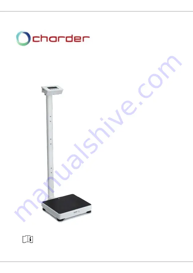
USER MANUAL
MS4970
Stand-on Floor Scale
Please keep the instruction manual at hand all the time for future reference.
Page 1: ...1 USER MANUAL MS4970 Stand on Floor Scale Please keep the instruction manual at hand all the time for future reference...
Page 2: ...for 2019 Separate collection for waste of electrical and electronic equipment in accordance with Directive 2002 96 EC Indicates that device conforms to 93 42 EEC as amended by 2007 47 EC Medical Devi...
Page 3: ...rnational copyright law All content is licensed and usage is subject to written authorization from Charder Electronic Co Ltd hereinafter Charder Charder is not liable for any damage caused by a failur...
Page 4: ...hermal Printer 16 III Indicator 17 A Indicator and Key Functions 17 B Display layout 18 IV Using Device 19 A Basic Operation 19 B Hold 19 C Tare 20 D Body Mass Index BMI 20 E Body Surface Area BSA 21...
Page 5: ...slippery surface Usage on soft surfaces ex carpet may result in inaccurate results Ensure all parts are properly locked and tightened before operating the device Safety Instructions Before putting dev...
Page 6: ...routine maintenance However regular checking of accuracy is recommended frequency to be determined by level of use and state of device If results are inaccurate please contact local distributor Warran...
Page 7: ...able and avoid sharp edges Do not overload extension cables connected to the device Route cables carefully to avoid tripping Keep device away from liquids Do not remove the plug by yanking on the cabl...
Page 8: ...guidance RF emissions CISPR 11 Group 1 The device uses RF energy only for its internal function Therefore its RF emissions are very low and are not likely to cause any interference in nearby electron...
Page 9: ...hospital environment Surge IEC 61000 4 5 1kV line s to line s 2kV line s to earth 1kV line s to line s 2kV line s to earth Mains power quality should be that of a typical commercial or hospital enviro...
Page 10: ...z 80 AM at 1 kHz 3 V m 80MHz to 2 7 GHz Portable and mobile RF communications equipment should be used no closer to any part of the device including cables than the recommended separation distance cal...
Page 11: ...S4970 Stand on Floor Scale The device is intended for use in an electromagnetic environment in which radiated RF disturbances are controlled The customer or the user of the device can help prevent ele...
Page 12: ...2 II Installation A Assembly Standard Column 1 Fasten and tighten four screws at the bottom of the base Ensure four adjustable feet and stability foot are at same level before using device Four screws...
Page 13: ...en battery housing cover 2 Take out battery housing 3 Place batteries in compartment ensure polarity is correct 4 Insert battery housing 5 Close battery housing cover 6 Turn on power to confirm that b...
Page 14: ...14 C Using Adapter 1 Connect adapter to indicator before connecting to mains power supply 2 Disconnect adapter from mains power supply before unplugging adapter pin from indicator AC Connector Port...
Page 15: ...o column using four flat head screws 2 Attach height rod to blocks using two flat head screws Item Name Quantity 1 Fixing block screws 4 2 Fixing blocks 2 3 Height Rod to fixing block screws 2 Photo o...
Page 16: ...16 E Attaching Thermal Printer Washer head screw M5 0 8 15mm Cross head screw M4 0 7 6mm...
Page 17: ...Zero Power button Press and hold to turn off Press once to zero weight 4 HOLD BMI Press once to Hold determine stable weighing value used when weight is unstable Press and hold for 3 seconds to enter...
Page 18: ...ng displayed NET Net weight appears after tare is activated HOLD Weight lock function is in use Stable symbol Indicates that weight is stable Negative symbol Weight under zero Zero symbol Weight is at...
Page 19: ...on indicator Note If subject s weight exceeds scale capacity including tare indicator will display Err prompt due to overload B Hold The hold function determines average weight designed to be used if...
Page 20: ...tand on device Conduct measurement 4 To clear tare value remove all objects from measurement platform and press key D Body Mass Index BMI 1 In normal mode press and hold the key to enter BMI mode 2 Di...
Page 21: ...ating BMI press key BSA will be displayed on indicator Press key to return to BMI mode Press key to return to normal weighing mode F Print If thermal printer is connected to indicator results can be p...
Page 22: ...t off automatically after a certain period of time Auto off options 120 sec 180 sec 240 sec 300 sec off Press to toggle between time options and to confirm selection Buzzer Beep When function is turne...
Page 23: ...o toggle between on off and TARE to confirm selection Wi Fi Setting optional If device has Wi Fi module installed this option will appear Press HOLD to toggle between Auto and PKEY Press TARE to confi...
Page 24: ...ata Manager can be used to connect the device to a PC The software program can be downloaded from the Charder website LINK URL https www chardermedical com download htm 2 Connect USB cable to device i...
Page 25: ...BMI calculation into software if needed Press Clear to clear all input NOTE information can also be input after weight measurement 2 Conduct measurement If Auto is selected results will be transmitte...
Page 26: ...hanges and multiple measurements for the same subject we recommend not changing the default file name 2 Result example If previous results were saved in 20190201 csv new results also need to be saved...
Page 27: ...a BSA data cannot be transferred to PC BSA results should be read from device indicator VII Wireless Connection If the device has the wireless or bluetooth module installed the indicator can transmit...
Page 28: ...ng chemical electrochemical or electrical interference unless damage is attributable to negligence on the part of Charder If device is not covered under warranty a service maintenance charge will appl...
Page 29: ...software is set up properly as indicated in this manual Distributor support required If the following errors occur we recommend contacting your local Charder distributor for repair or replacement ser...
Page 30: ...low Error normally caused by faulty loadcell or wiring Please contact distributor Zero count over calibration zero range 10 while power on Remove weight from device and try again If error persists pl...
Page 31: ...5 digits Dimensions Overall 360 W x 480 D x 1100 H mm Platform 360 W x 310 D x 70 H mm Column 1026 mm Device Weight 8 1 kg Key Functions Unit On Off Zero Send Data Hold BMI Tare BSA Power Supply 6 AA...
Page 32: ...32 B Power Adapter Standards Warning The device is only compatible with the power adapters specified in the dashed block below...
Page 33: ...________________________________________________ _______________________________________________________ _______________________________________________________ _______________________________________...
Page 34: ...visions of the below stated directives 93 42 EEC as amended by 2007 47 EC Medical Device Directive Please see separate document showing on sticker of device for above CE marking Authorized EU Represen...