CHA TD
Page 8
o.
UHF Plug
UHF Plugs, PL-259, are attached to both ends of
the Coaxial Cable (j) assembly.
p.
Resistor Connection
The Resistor Connection, see plate (4), are
located at both ends of the Termination Resistor
(g).
q.
Resistor Eyebolt
The Resistor Eyebolts, see plate (4), are located
at both ends of the Termination Resistor (g).
r.
Wire Connector
The Wire Connectors are located at both ends of
the Antenna Wires (b) and one end of the
Counterpoise Wires (c).
s.
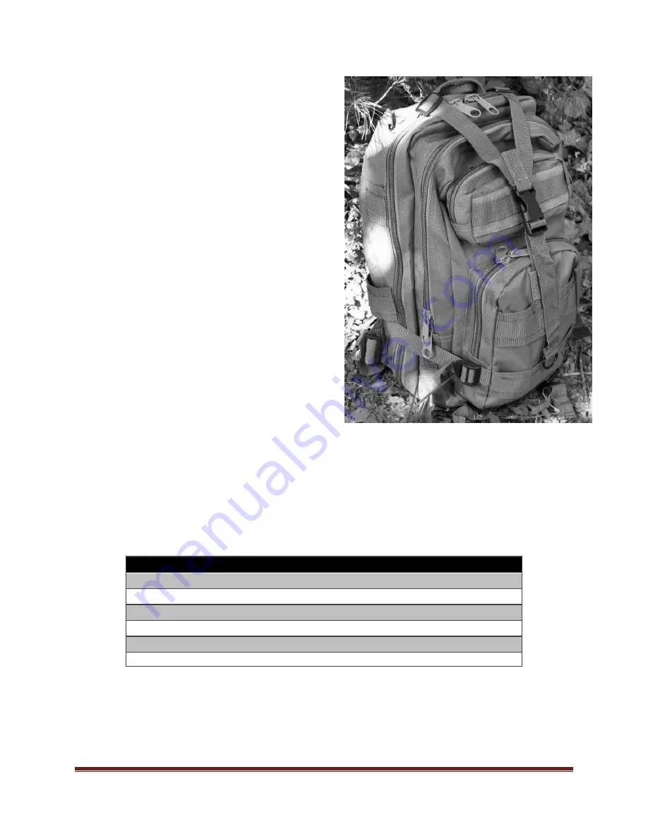
Backpack
The Backpack, see plate (6), stores and
organizes the components of the CHA TD,
enabling rapid deployment and recovery, and
making the antenna portable and man-packable.
Plate 6. Backpack.
Antenna Configurations
Using the supplied components, the CHA TD can be deployed into a number of configurations. Six configurations
are described in this manual, each with unique performance characteristics. Table (2) shows the antenna
configurations described in this manual. The table can assist the operator to quickly select the most appropriate
antenna configuration to meet their operational requirements.
Configuration
Ground Short Medium Long Directionality
Deployment
Sloping “V”
↕
↑
Unidirectional
Deliberate
Horizontal Dipole
↓
↕
↑
Bidirectional
Deliberate
Sloping Wire
↓
↕
Omnidirectional Hasty
Inverted “L”
↓
↕
Unidirectional
Deliberate
Horizontal NVIS
↓
↑
Omnidirectional Hasty
Half Rhombic
*
↕
Unidirectional
Hasty
Table 2. Antenna Configuration Selection.
To use the table, decide which distance column (Ground = 0 to 90 miles, Short = 0 - 300 miles, Medium = 300 –
1500 miles, Long > 1500 miles) best matches the distance to the station with whom you need to communicate.
Then, determine if the OWF is in the lower (↓ = 1.8 – 10 MHz) or upper (↑ = 10 – 30 MHz) frequency range.
Finally, select the CHA TD configuration with the corresponding symbol in the appropriate distance column. All


