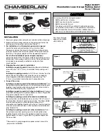
White Grey
Red
Wire Nut
Connection
Wire
White
Connection
Wire
White/Black
Connection
Wire
Parking Assist
Wires
Safety
Reversing
Sensor Wires
Insert Into Appropriate Terminals
Parking Assist
Wires
120 Vac Power Adapter
White (-)
White/Black (+)
Wire
Nuts
®
Model CLULP1
Chamberlain Laser Garage Parking Assist
Owner’s Manual
To avoid eye INJURY or damage to product:
• NEVER point the laser at anyone.
• NEVER look directly into the laser beam.
• NEVER disassemble the laser.
• The parking assist is NOT a substitute for safe parking practices.
• Use of controls or adjustments, or the performance or procedures
other than specified can result in hazardous radiation exposure.
• ONLY for use on Chamberlain manufactured garage door openers.
WARNING
CAUTION
WARNING
WARNING
Figure 1
Figure 3A
Figure 3B
Insert into appropriate terminals
Red White Grey
Parking Assist Wires
Safety Reversing
Sensor Wires
Parking Assist Wires
120 Vac Power Adapter
White (-)
White/Black (+)
Figure 2B
INSTALLATION
1. Open yo
u
r garage door and park yo
u
r
v
ehicle o
u
tside of garage.
2. Determine the mo
u
nting location on the ceiling and fasten the
parking assist
u
sing scre
w
and anchor (Fig
u
re 1).
3.
For installation on a Chamberlain garage door opener:
Locate the q
u
ick connect terminals on yo
u
r motor head.
Temporarily remo
v
e the
w
ires for the safety re
v
ersing sensors
(see yo
u
r o
w
ner’s man
u
al for the location of the q
u
ick connect
terminals.). The po
w
er adapter
w
ill not be needed, discard it.
For all other installations (power adapter required):
Locate the nearest 120
V
ac po
w
er o
u
tlet to the parking assist(s).
Ro
u
te
w
ires from parking assist(s) to o
u
tlet. The po
w
er adapter
is intended to be correctly oriented in a
v
ertical or floor
mo
u
nt position.
4.
Stripping the wires prior to installation:
Installing one parking assist:
Separate
w
hite and
w
hite/black
w
ires and strip 7/16" (11 mm) of ins
u
lation from parking assist
w
ires.
Installing two parking assists:
C
u
t 6" (15 cm) of
w
ires from the
end of one set of parking assist
w
ires for
u
se as connection
w
ires. Separate
w
hite and
w
hite/black
w
ires and strip 7/16"
(11 mm) of ins
u
lation from both ends of connection
w
ire.
5.
Connect the wires:
Installing one parking assist (Chamberlain installation):
T
w
ist
like colored
w
ires for parking assist and safety re
v
ersing sensors
together. Insert t
w
isted
w
ires into q
u
ick-connect holes:
w
hite to
w
hite and
w
hite/black to grey* (Fig
u
re 2A).
Installing one parking assist (all other installations):
Connect
w
ires from parking assist to po
w
er adapter as sho
w
n (Fig
u
re 2B).
Pl
u
g po
w
er adapter into 120
V
ac o
u
tlet.
Installing two parking assists (Chamberlain installation):
Separate
w
hite and
w
hite/black
w
ires and strip 7/16" (11 mm) of
ins
u
lation from the end of parking assist
w
ires. T
w
ist like colored
w
ires for parking assists, safety re
v
ersing sensors and
connection
w
ire together. Sec
u
re
w
ith
w
ire n
u
t. Insert connection
w
ires into q
u
ick-connect holes:
w
hite to
w
hite and
w
hite/black to
grey* (Fig
u
re 3A).
Installing two parking assists (all other installations):
T
w
ist
like colored
w
ires from parking assists and connection
w
ires
together. Sec
u
re
w
ith
w
ire n
u
t and attach connection
w
ires to
po
w
er adapter as sho
w
n (Fig
u
re 3B). Pl
u
g po
w
er adapter into
120
V
ac o
u
tlet.
*
Please refer to your garage door opener owner’s manual for
proper wire installation.
CAUTION
ATTENTION
132C2469-1
LASER RADIATION
DO NOT STARE INTO BEAM
RAYONNEMENT LASER
NE PAS REGARDER DIRECTEMENT
LE RAYONNEMENT LASER
Maximum power output: < 1mW @ 635 - 670nm
Puissance de sortie maximum: < 1mW @ 635 - 670nm
CLASS II LASER PRODUCT
APPAREIL AU LASER DE CLASSE II
This Class B digital
apparat
u
s complies
w
ith ICES-003.
Wire Nut (2)
Parking Assist
Screw 6ABX1-1/4"
Anchor
120 Vac Power Adapter
CARTON INVENTORY
Figure 2A


