


Challenger_ASFP1_Instructions_Rev01
ASFP1
MOTION DETECTOR
The Motion Detector is designed with two detecting sensors, Passive Infra-Red
(PIR) sensor and light sensor, in order to fulfill the purpose of security and home
automation. When the detector is cooperated with security appliances, it is acting
as a security device by detecting changes in infra-red radiation levels. If a person
moves within or across the device field of vision, a trigger radio signal will be
transmitted to cause full alarm condition. Alternatively, when the detector is
worked with home automation appliances, the detector can be set to perform the
role of home automation device by detecting both changes in infra-red radiation
levels and percentage of lux levels. Once night falls, the percentage of ambient
illumination is lower than preset value. If a person moves within or across the device
field of vision, a trigger radio signal will be transmitted so as to turn on the
connected lightings for better illumination.
The PIR Detector requires a CR123A 3.0V Lithium battery which under normal
conditions will have typical life in excess of 1 year. When the battery level drops to
an unacceptable level, the LED behind the detection window will flash once every
30 seconds. When this occurs the batteries should be replaced as soon as possible.
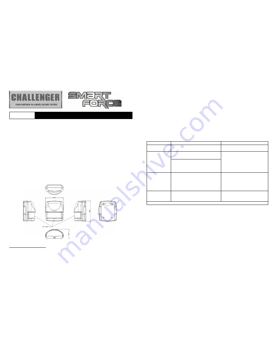
Product Overview
IMPORTANT NOTE:
The motion detector supplied in the kit HAS already been
learnt to the Gateway Hub and does not require learning to the ASFK1 Gateway
Hub. For replacement or additional PIR’s these will need to be learnt to the
Gateway Hub before installation.
LEARNING MOTION DETECTOR
Please refer to Smart Force Quick Set Up Guide. The easiest way to learn the
device is either via through the Smart Force Web Site or Smart Force App once you
have completed the System Registration.
On the back of the PIR PCB there is a tamer switch, this is also used to carry out
learning to the Gateway Hub and reset. When the detector is first powered up,
the LED flashes on and off alternately and repeatedly at 2-second intervals. This is
to indicate that device has not been assigned to the Gateway Hub and will not
work.
Put the Gateway Hub in to learn mode via the Smart Force Web User Interface or
Smart Force App. Then select add a device.
Function
Description
Indication
Device Not
Learnt
The Gateway Hub has not
allocated or Learnt the PIR
2-second on, 2-second off for 2
minutes.
Learn Mode
1. Gateway Hub entered learn
mode
1. Waiting to Learn, LED ON
0.5 second, OFF 0.5 second
2. Success, the green LED will
be bright for 0.5 second.
3. Fail, the green LED will flash
3 times.
2. Pressing tamper switch 3 times
within 1.5 second and release
in 6 seconds, the PIR will enter
learn mode.
Reset
1. In the 30-second learn mode,
press the tamper switch for
6~10 seconds, this will delete
the device from Gateway Hub.
1. Press the Tamer Switch for 6
seconds, the LED will light
be constant.
2. Fail, the green LED will flash
3 times.
Empty ID code
1. IDs are excluded and all of
preset value will be reset to
factory default.
1. The orange light will
2-second on, 2-second off
Failed or success learning can be viewed from the Gateway Hub website or App.
Choosing a Mounting Location
Please ensure the motion sensor is within signal range of the Gateway Hub prior to
mounting.
The PIR Detector is suitable for mounting in dry interior locations only.
The recommended position for a PIR Detector is in the corner of a room mounted at
a height between 1.8 and 2m. At this height, the PIR detector will have a maximum
range of up to 9m with a field of view of 110
°
, subject to the position for the PCB
being set in 5. (FIGURE 1& 2) The position of the PCB inside the PIR can be set to
5 different positions to adjust the range of the detector. Setting the PCB in position 3
will reduce the range to 6m approximately, with position 1 providing a range of 3m
approximately. The recommended position setting for the PCB is in position 5.