Chapter VI Measurement System
52
6.1.5 Gating
It is used to limit measurements in specific parts of the waveform.
Click [Gating] menu key, and the Gating will be switched between the screen and cursor. The data in the
waveform area of the screen or between the cursors can be selected for measurement and calculation.
6.1.6 Reference Levels
The [Reference Levels] is used to determine how to carry out time-related measurement.
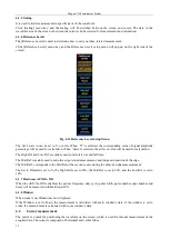
Click [Reference Levels] menu key, and the Reference Levels setup menu will pop up on the right side of the
screen:
Fig. 6.13 Reference Levels Setup Menu
The Set Levels in can be set to % or units. When
“
%
”
is selected, the corresponding value of signal amplitude
percentage will be used for calculation. When
“
units
”
is selected, the set level value will be used for calculation.
The High Ref and Low Ref are mainly used to calculate rise and fall time.
The Mid Ref is mainly used to calculate edge-related measurement, and judge mid position of the edge.
The Mid Ref2 corresponds to the Mid Ref of the second source during the delay and phase measurement.
The Set to Defaults is set to %, the High Ref is set to 90%, the Mid Ref is set to 50%, and the Low Ref is set to
10%.
6.1.7 Hardware AUX On Off
When the AUX On Off is enabled, the period, frequency, duty cycle, pulse width, pulse number, edge number and
delay will be measured with Hardware AUX.
6.1.8 Window
When zoom is on, Window menu is displayed.
If the Window is set to Main, the measurement is calculated with main window’s data, if the window is set to
zoom, the measurement is calculated with zoom window’s data.
6.2
Cursor measurement
The cursor is a mark for positioning the waveform on the screen, which is used for manual measurement of the
acquired data. The cursor is composed of horizontal and vertical lines.
Summary of Contents for 4456 Series
Page 10: ...VIII...
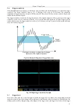
Page 55: ...Chapter V Trigger System 45 Fig 5 51 RF Test Signal Example...
Page 69: ...Chapter VII Mathematical Operation 59 Fig 7 10 Advanced Math Example...
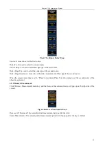
Page 71: ...Chapter VIII Display System 61 Fig 8 3 Wfm Palette Menu Fig 8 4 Normal Palette...
Page 72: ...Chapter VIII Display System 62 Fig 8 5 Inverted Palette Fig 8 6 Temperature Palette...
Page 75: ...Chapter VIII Display System 65 Fig 8 12 XY Display Example...
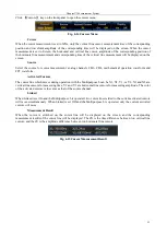
Page 165: ...Chapter XI Protocol Analyzer Option 155 Fig 11 242 1553 Trigger and Analysis Example...

