background image

Chapter XI Protocol Analyzer (Option) 

136 


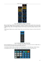
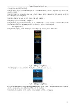
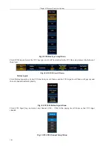
Fig. 11.185 Number Format Setup Menu 

Rotate the Multipurpose b to select the corresponding number format, and then press it down to confirm Select, or 
directly click the corresponding option of the Level3 Menu for direct settings; 

Click [Bus Offset] key, and then rotate the Multipurpose b to change the bus position in the vertical direction of 
the display area; 

Click [Waveforms Offset] key, and then rotate the Multipurpose b to change the waveform position in the vertical 
direction of the display area; 


Event table setup 

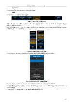
Click [Event Table] key, and the Event Table setup menu will pop up on the right side of the screen: 


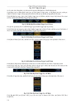
Fig. 11.186 Event Table Setup Menu 

Click [Event Table] key to close or open the event table; 

Click [Save] key, and save the event table information. 


Bus switch setting 

Click [Bus Switch] key, and enable or disable the bus decoding function. 

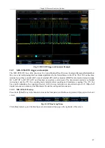
11.7.2  Audio trigger setup 

When  the Audio  type is I2S,  LJ  or RJ,  it can  be  triggered according to  Word Select  and Data. When the Audio 
type is TDM, it can be triggered according to Frame Sync and Data. 

Press down 

Trigger

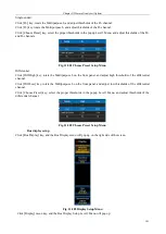
  key on the front panel to pop up the Trigger Level1 Menu; click [Type] key to pop up the 

Trigger Level2 Menu, and click [Bus] key to pop up the Audio Trigger Level1 Menu. Click [Trigger On] key, pop 
up the Trigger Level2 Menu, and select the type. 


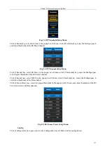
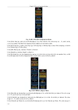
Fig. 11.187 Trigger When Setup Menu 


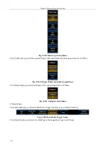
Word Select 

Click [Word Select] key, and select Word Select trigger. 

Summary of Contents for 4456 Series

Page 1: ...4456 Series Digital Phosphor Oscilloscope User Manual China Electronics Technology Instruments Co Ltd...

Page 2: ...he applications menu structure operation method precautions for use basic working principle etc of the 4456 series digital phosphor oscilloscope to help you familiarize yourself with and master the op...

Page 3: ...zer extended ports 6 2 2 4 Waveform generator extended ports 6 2 2 5 1kHz Calibration Signal 6 2 2 6 Screen Display Area 6 2 2 7 Multipurpose Setup Area 7 2 2 8 Feature Setup Area 7 2 2 9 Run Control...

Page 4: ...ONS 23 5 2 TRIGGER SOURCE 23 5 3 TRIGGER TYPE 24 Edge trigger 24 Pulse trigger 26 Runt trigger 28 Sequence Trigger 30 Logic trigger 31 Setup Hold Times trigger 34 Rise Fall Time trigger 35 Video and H...

Page 5: ...FERENCE 68 CHAPTER X SYSTEM CONFIGURATION 71 10 1 CONFIG 71 10 2 REFERENCE AUX OUT 72 10 3 NETWORK CONFIGURATION 73 10 4 OPTIONS 74 10 5 CALIBRATION 74 10 6 SYSTEM WRITE PROTECTION 75 CHAPTER XI PROTO...

Page 6: ...igger setup 151 CHAPTER XII LIMIT MASK TEST OPTION 156 12 1 SET UP MASK 156 12 2 SELECT MASK 157 12 3 SET UP TEST 158 12 4 RUN TEST 159 12 5 SHOW RESULTS 159 CHAPTER XIII POWER MEASUREMENT AND ANALYSI...

Page 7: ...uare 179 15 1 3 Ramp 180 15 1 4 Pulse 180 15 1 5 DC 181 15 1 6 Noise 182 15 1 7 Arbitrary 182 15 1 8 Built in 185 15 2 MODULATION 186 15 2 1 Modulation Type 186 15 2 2 Frequency FSK Rate 187 15 2 3 Sh...

Page 8: ...16 9 P8100 HIGH VOLTAGE DIFFERENTIAL PROBE 206 16 9 1 Instructions for Safe Use 206 16 9 2 Operating Instructions 206 16 9 3 Main Parameters of Probe 209 16 10 P5020 HIGH VOLTAGE DIFFERENTIAL PROBE 2...

Page 9: ...228 CHAPTER XIXAPPLICATION EXAMPLES 230 19 1 MEASURING SIMPLE SIGNAL 230 19 2 MEASURING PULSE SIGNAL 230 19 3 VIEWING PHASE DIFFERENCE BETWEEN TWO SIGNALS 231 19 3 1 XY Measurement Method 231 19 3 2...

Page 10: ...VIII...

Page 11: ...d documents in the packaging box include Main unit of the 4456 series oscilloscope 4456C CM D DM E EM 1 Power cord 1 Passive voltage probe 4 Certificate of Conformity 1 User Manual of 4456 Series Digi...

Page 12: ...s maintenance China Electronics Technology Instruments Co Ltd has nationwide outlets and offices and the technical support personnel in each outlet and office can quickly reach the user s premise for...

Page 13: ...It is a kind of hazard warning which is intended to remind the user of important precautions The incorrect operation may cause damage to the instrument or lead to personal injury Some key precautions...

Page 14: ...phor oscilloscope please check the power supply unit according to the Power supply requirements in Chapter I Power on the digital oscilloscope after confirming that power supply is correct Instruction...

Page 15: ...nted in the form of XXX and XXX denotes the name of the menu 2 2 Overview of front panel This section will give a detailed description of the front panel of the 4456 series oscilloscope You can become...

Page 16: ...rator Ports The waveform generator extended ports are used for the waveform output of 1 channel with 50 output impedance The extended ports will be opened when the 4456 H02 option is selected 2 2 5 1...

Page 17: ...a is mainly used for selection of Level1 Menu and Level2 Menu Turn it left or right to change the selection and press it down for confirmation The Multipurpose b is mainly used for selection of Level...

Page 18: ...ion of the oscilloscope which observes details of the waveform mainly through different windows 6 Navigate It is used for trigger search and waveform recording and playback of the oscilloscope 7 Math...

Page 19: ...3 AutoSet It is used for the automatic waveform setting of the oscilloscope The vertical system horizontal system and trigger system are automatically set to get a more appropriate waveform display 4...

Page 20: ...idth limit channel delay and probe setting 2 2 It is used to set the vertical system of the Channel2 of the oscilloscope including the channel switch input impedance bandwidth limit channel delay and...

Page 21: ...Chapter II About the 4456 Series Digital Phosphor Oscilloscope 11 AUX OUT 10 MHz IN OUT AUX IN LAN VIDEO OUT USB DEVICE USB HOST Power input LAN Fig 2 17 Schematic Diagram of Rear Panel...

Page 22: ...of each analog channel which has Push to Zero function Adjustment scope 1 mV div 100 mV div 1 V 200 mV div 1 V div 10 V 2V div 10V div 100V 3 2 Probe 3 2 1 Probe port There are 4 analog channels on t...

Page 23: ...ation including the vertical scale termination coupling status invert status and probe attenuation coefficient will be displayed at the bottom status bar of the screen When the channel is closed the i...

Page 24: ...measured signal will be blocked When any channel key CH1 CH4 is pressed down open the channel menu for bandwidth limit setting of the channel Click Bandwidth menu key and the Bandwidth option will be...

Page 25: ...to set the voltage and current probe type according to the measurement type of the currently connected probe 3 7 3 Probe Zero Calibrate When the connected probe is an active voltage probe click Probe...

Page 26: ...tical range Operate the Scale knob of any channel to set the vertical range gear of the corresponding channel When Fine Scale is disabled the gear will be increased and decreased according to steps 1...

Page 27: ...ith an adjustment range of 150 ns and a step of 400 ps for standard types 4456C D E and with an adjustment range of 150 4 ns and a step of 800 ps for economical types 4456CM DM EM When any channel key...

Page 28: ...he horizontal system mainly includes setting of parameters including time base delay time acquire mode and window extension Fig 4 2 Horizontal System Operation Area 4 1 Description of Keys Buttons Tab...

Page 29: ...layed and then you can quickly realize horizontal movement of the waveform through multi touch of the touch screen 4 4 Zoom The Zoom function can be used to zoom in a segment of waveform to check the...

Page 30: ...his point is consistent with the sample mode Calculate the average of the obtained waveform points after multiple captures and then generate the final display waveform The Average mode is intended to...

Page 31: ...e Memory setup menu Fig 4 9 Memory Menu Click the corresponding key of the required memory depth to set the memory depth Attention When the 4456C D E is in a Sample mode the max memory depth can be se...

Page 32: ...on and the Segment menu key will be effective Fig 4 10 Segment Memory Setup Menu 4 7 Quick Acq In the Quick Acq mode the waveform collected will be saved by 1k depth memory in the FPGA In this mode th...

Page 33: ...set the trigger type and trigger mode Force Press it down to forcedly trigger the oscilloscope once Level It is used to adjust trigger level and has the Push for 50 function 5 2 Trigger source Press d...

Page 34: ...r LIN Trigger I2S Trigger USB Trigger FlexRay Trigger 1553 Trigger and Visual Trigger Area Trigger which help users locate events in which they have interest out of complicated sample information Edge...

Page 35: ...e in the waveform area will disappear within about 3 s after the knob operation stops Attention When the source is Aux or AC or digital channel no trigger mark and trigger level line will be displayed...

Page 36: ...nnected external channel signal Settable options 1 10 Pulse trigger Trigger on a positive or negative pulse of the specified width of the input signal Trigger type Press down Trigger key of the trigge...

Page 37: ...nu Click Width menu key to set the pulse width through the Multipurpose b or numeric keypad Pulse width adjustment range 0 8 ns 10 s Trigger level Press down Level key on the front panel to modify the...

Page 38: ...Diagram of Runt Pulse Trigger type Press down Trigger key of the trigger control area on the front panel and open the trigger menu Click Type menu key and click Runt key in the popup Type menu to sel...

Page 39: ...o be smaller than a certain time value which can be set by rotating the Multipurpose b with a range from 6 4 ns to 12 8 s Click Runt Width and set the trigger time to be larger than a certain time val...

Page 40: ...n the top right corner of the screen Trigger source Click Source menu key and the Source selection menu will pop up on the right side of the screen The CH1 CH4 can be made as the source Slope Click Sl...

Page 41: ...ger It will be triggered when any logic code pattern of the channel becomes false or remains true in the specified time and any input can be used as a clock to find the code pattern on the clock slope...

Page 42: ...nel can be set to Low L Click X Don t Care menu key and the current channel can be set to X Don t Care Define logic Click Define Logic menu key and the Logic Function setup menu will pop up on the rig...

Page 43: ...which can be set by rotating the Multipurpose b with a range from 6 4 ns to 12 8 s Logic Thresholds Click Level menu key and the Logic Thresholds setup menu will pop up on the right side of the scree...

Page 44: ...time of the clock slope The setup time is the length of time that the input signal is stable and unchanged before the appearance of clock slope and the hold time is the length of time that the input...

Page 45: ...ing the Multipurpose b with a range from 6 4 ns to 12 8 s Click Hold Time menu key and set the hold time by rotating the Multipurpose b with a range from 6 4 ns to 12 8 s Thresholds Click Thresholds m...

Page 46: ...n Trigger source Click Source menu key and the Source selection menu will pop up on the right side of the screen The CH1 CH4 can be made as the source Slope Click Slope menu key and the Slope setup me...

Page 47: ...key and set the Trigger When to be equal to a certain time value which can be set by rotating the Multipurpose b with a range from 6 4 ns to 12 8 s Click Time menu key and set the Trigger When to be n...

Page 48: ...gger menu Fig 5 37 Video Trigger Menu Click Type menu key and click Page Down key in the popup Type menu and the Page Down Type selection menu will pop up Click Video key to select the Video Trigger T...

Page 49: ...the TV scan line is 525 with the even field in front of the odd field PAL The frame frequency is 25 frames s and the number of the TV scan line is 625 with the odd field in front of the even field SEC...

Page 50: ...to All Lines Click Line Number menu key and set the Trigger On to one line Rotate the Multipurpose b to set the line number Polarity Click Polarity menu key and set the trigger to Normal or Inverted F...

Page 51: ...setup menu Fig 5 41 Zone Menu Source Select the waveform of the corresponding channel as the Zone source Zone The In and Out can be selected for judgment On Off When the ZoneQualified is on it can be...

Page 52: ...be displayed when there is no signal input Normal The waveform display will be refreshed when the trigger condition is satisfied When the trigger condition is not satisfied it will keep the original w...

Page 53: ...so as to ensure that small signal can be stably triggered If the signal contains noise the trigger sensitivity can be set to 2 divisions or larger to ensure that the signal with large noise can be st...

Page 54: ...nal output The AUX OUT is the signal output of trigger pulse by default which can be used for trigger synchronization function of multiple instruments and waveform capture rate test of the 4456 series...

Page 55: ...Chapter V Trigger System 45 Fig 5 51 RF Test Signal Example...

Page 56: ...sitive pulse width The time difference between the 50 threshold of the pulse Rise Edge and the 50 threshold of the next Fall Edge Negative pulse width The time difference between the 50 threshold of t...

Page 57: ...The ratio between the difference between the min value and the base value of the waveform and the amplitude Top Fall The ratio between the difference between the max value and the top value of the wav...

Page 58: ...b The analog channel waveform reference waveform and mathematical operation waveform mainly include the period frequency rise time fall time positive duty cycle negative duty cycle positive pulse widt...

Page 59: ...the delay measurement of the edge of the second source When the measurement type is set to Phase press down Phase To in the menu to set the second source of the phase measurement 6 1 2 Remove Measure...

Page 60: ...menu will pop up on the right side of the screen Fig 6 10 Waveform Histograms Menu Mode Off No histogram will be displayed Vertical The vertical histogram will be displayed Horizontal The horizontal...

Page 61: ...current statistics of the histograms and carry out statistics and count again 6 1 4 Statistics Click Statistics menu key and the Statistics setup menu will pop up on the right side of the screen Fig 6...

Page 62: ...ion The High Ref and Low Ref are mainly used to calculate rise and fall time The Mid Ref is mainly used to calculate edge related measurement and judge mid position of the edge The Mid Ref2 correspond...

Page 63: ...ated Cursors The cursor line which moves during operation with the Multipurpose b can be X1 X2 Y1 or Y2 X1 and X2 are vertical line cursors for measuring time Y1 and Y2 are horizontal line cursors for...

Page 64: ...r is not set to off the mathematical operation status bar will be displayed at the bottom of the screen displaying the vertical scale and operation expression of the operation waveform Fig 7 3 Dual Wf...

Page 65: ...n it is set On the corresponding amplitude and frequency can be displayed at the FFT waveform peak SubPeak Mark When it is set On the corresponding amplitude and frequency can be displayed at the FFT...

Page 66: ...t the top of the screen waveform area Vertical Units Select the FFT operation unit including V dBV dBmV mV Center Freq Set the corresponding frequency of the center of the screen which can be input by...

Page 67: ...uired Source and Operator can be selected by pressing down the Multipurpose b or by directly clicking the option and the selected option will be input to the expression Delete The finally entered opti...

Page 68: ...set by setting the menu E The values are expressed with scientific notation Example Carry out integral operation of signals of Channel1 1 Select Intg 2 Select CH1 3 Select 4 Click Execute Expression C...

Page 69: ...Chapter VII Mathematical Operation 59 Fig 7 10 Advanced Math Example...

Page 70: ...h lightness of color 256 grade gray scale or temperature change color grade and to provide 4 types of waveform palettes including normal inverted temperature and spectral which enhances the capability...

Page 71: ...Chapter VIII Display System 61 Fig 8 3 Wfm Palette Menu Fig 8 4 Normal Palette...

Page 72: ...Chapter VIII Display System 62 Fig 8 5 Inverted Palette Fig 8 6 Temperature Palette...

Page 73: ...y of the display menu and open the Graticule menu Fig 8 8 Graticule Menu Click the menu key to set the graticule to the corresponding type Full Display the background grid and coordinates Grid Display...

Page 74: ...urement According to sin A B or C D where is the phase difference angle between the channels and definitions of A B C D are as shown in the above figure Therefore the phase difference angle can be obt...

Page 75: ...Chapter VIII Display System 65 Fig 8 12 XY Display Example...

Page 76: ...R1 R4 can be selected If want to save to disk Save to file can be selected and files can be made in CSV or bin format If Save to file is selected the all opened channel can be selected with source The...

Page 77: ...ecision number 0x6F Null data 0 8 bit char Waveform Data 0x70 Data waveform starting address Normal Average acquire mode each sampling points contains one 8 bit char High resolution acquire mode each...

Page 78: ...s of the disk The file format can be 16 bit bmp 24 bit bmp and 32 bit bmp or tif The default file name is 4456_YYYYMMDD_HHMM The YYYYMMDD is the year month and day information of the current date and...

Page 79: ...ff the Ref Wfm display When the Ref Wfm display is turned on the Ref Wfm setup menu will be displayed on the right side of the screen Fig 9 7 Ref Wfm Setup Menu Rotate the Multipurpose b to adjust the...

Page 80: ...in waveform record When all data segments are recorded the instrument will stop automatically Note The number of recorded data segment is consistent with the number of saved setting segment in the acq...

Page 81: ...res Gesture Control Slide to the left The trigger point and waveform horizontally move to the left Slide to the right The trigger point and waveform horizontally move to the right Slide up The vertica...

Page 82: ...gnal trigger output and limit mask output Main Trigger One pulse will be output when there is a trigger during the internal acquire Limit mask output The pulse will be output when the limit mask test...

Page 83: ...scope It includes IP address and port Click Network Configuration menu key and open the Network Configuration menu Fig 10 5 Network Configuration Menu Click Socket Server menu key to turn on or turn o...

Page 84: ...and analysis CAN trigger and analysis LIN trigger and analysis FlexRay trigger and analysis Audio trigger and analysis USB trigger and analysis and 1553 trigger and analysis Click Optional Module menu...

Page 85: ...so as to ensure the safety of the instrument system If you need to change the data of disc C or install drivers such as printer carry out following operations Press down Utility key to pop up the Syst...

Page 86: ...al rate 10Mbps CAN option S07 Signal rate 10kbps 1Mbps LIN option S08 Signal rate 800bps 100kbps Protocol standard 1 x 2 x FlexRay option S09 Signal rate 2 5Mbps 5Mbps 10Mbps Audio option S10 Signal r...

Page 87: ...t the bottom of the screen Fig 11 4 I2C Bus Setup Menu Define inputs setup Click Define Inputs menu key and the I2C Inputs setup menu will pop up on the right side of the screen Fig 11 5 I2C Define In...

Page 88: ...selected channel will be displayed on the menu item on the right side Threshold setup Click Thresholds menu key and the I2C Channel Threshold setup menu will pop up on the right side of the screen Fig...

Page 89: ...holds menu key When rotating the Multipurpose b to change the threshold the preset type will be changed to the User Include R W in address Click Include R W in address menu key and the Include R W in...

Page 90: ...Offset menu key and then rotate the Multipurpose b to change the waveform position in the vertical direction of the display area Attention The Waveforms Offset button will be displayed when the displa...

Page 91: ...d at the bottom of the screen Fig 11 17 Trigger Type Setup Menu Attention When the bus decoding type is I2C and it is switched to protocol trigger the protocol trigger menu will automatically switch t...

Page 92: ...trigger type will be set to Missing Ack Click Address menu key and set the I2C trigger type to Address and the menu at the bottom of the screen will be switched to the Trigger Type setup menu Fig 11 1...

Page 93: ...C direction to Read Write or R W Click Data menu key and set the I2C trigger type to Data and the menu at the bottom of the screen will be switched to the Data Trigger Type setup menu Fig 11 23 Trigge...

Page 94: ...nalysis Example 11 2 RS232 RS422 RS485 UART trigger and analysis The RS232 protocol analyzer option can analyze the RS232 RS422 RS485 and UART buses When the user selects RS232 bus the input polarity...

Page 95: ...y and the Bus Type selection menu will pop up on the right side of the screen Fig 11 30 Bus Type Setup Menu Click RS232 key and select the RS232 bus type and the RS232 Bus setup menu will be displayed...

Page 96: ...as the receiving channel If Off is selected it means that no Rx channel will be set Fig 11 34 RS232 Channel Setup Menu Click Polarity key and select Normal or Inverted Normal means that the high level...

Page 97: ...olds of the Rx channel Click Choose Preset key select the preset thresholds in the popup Level3 Menu and adjust thresholds of the Tx and Rx channels Fig 11 36 Choose Preset Setup Menu Config Click Con...

Page 98: ...ansmission When the End of Packet is turned on several data blocks will be combined accordingly Click End of Packet key and set the End of Packet character during data transmission which can be set to...

Page 99: ...t Rate and then press it down to confirm Select or directly click the corresponding option to select the Bit Rate Bus display setup Click Bus Display key and the Bus Display menu will pop up on the ri...

Page 100: ...e display area Click Waveforms Offset key and then rotate the Multipurpose b to change the waveform position in the vertical direction of the display area Event table setup Click Event Table key and t...

Page 101: ...Packet key and select the Tx Rx End of Packet trigger Tx Rx Data Click Tx Data key or Rx Data key and select the Tx Rx Data trigger Fig 11 48 Data Setup Menu Click Data key pop up the Tx or Rx Data In...

Page 102: ...rity Error key or Rx Parity Error key and select the Tx Rx Parity Error trigger Fig 11 51 RS232 Trigger and Analysis Example 11 3 SPI protocol trigger and analysis The SPI bus is composed of the SS ch...

Page 103: ...Bus setup menu will pop up on the lower screen Fig 11 53 Bus Setup Menu Click Bus menu key and the Bus Type selection menu will pop up on the right side of the screen Fig 11 54 Bus Type Setup Menu Cl...

Page 104: ...Click SCLK Input key and select any channel CH1 CH4 in the popup Level3 Menu as the SCLK channel Fig 11 57 SPI Channel Setup Menu Click SS Input key and select any channel CH1 CH4 in the popup Level3...

Page 105: ...ds Click Thresholds key to pop up the Channel Threshold Level2 Menu set the SCLK SS MOSI and MISO thresholds Firstly select the channel rotate the Multipurpose b on the front panel to change the thres...

Page 106: ...ey rotate the Multipurpose b and adjust thresholds of the MOSI channel Click Channel key select MISO in the popup Level2 Menu click Thresholds key rotate the Multipurpose b and adjust thresholds of th...

Page 107: ...Click MISO Level key to select Active High or Active Low and set the MISO data line polarity bit to Active High Active High is 1 or Active Low Active Low is 1 Click Word Size key and rotate the Multip...

Page 108: ...ill pop up Fig 11 67 Number Format Setup Menu Rotate the Multipurpose b to select the corresponding number format and then press it down to confirm Select or directly click the corresponding option of...

Page 109: ...ISO MOSI and MISO Press down Trigger key on the front panel to pop up the Trigger Level1 Menu click Type key to pop up the Trigger Level2 Menu and click Bus key to pop up the SPI Trigger Level1 Menu C...

Page 110: ...Multipurpose b to select number of bytes of the input data It will be set to 1 by default Click MISO Data key and input data by opening the data input keyboard MOSI MISO Click MOSI MISO key and selec...

Page 111: ...key in the Function Area on the front panel and the Bus setup menu will pop up on the lower screen Refer to the I2C bus As shown in the figure click Bus menu key and the Type selection menu will pop u...

Page 112: ...splayed on the menu item on the right side The CAN bus signal type includes types including the CAN_L CAN_H Tx Rx and differential When the differential signal is connected the positive pole and negat...

Page 113: ...reater smaller than the max min threshold under this range the max min threshold will be displayed If the preset type is not set to the User click Thresholds menu key When rotating the Multipurpose b...

Page 114: ...ultipurpose b to change it When selecting other Bit Rate preset type the corresponding Bit Rate will be displayed on Bit Rate menu key If the preset type is not custom click Bit Rate menu key and then...

Page 115: ...ertical direction of the display area Attention The Waveforms Offset button will be displayed when the display mode is Bus and Waveforms Event table setup Click Event Table menu key at the bottom of t...

Page 116: ...and the CAN Trigger Type setup menu will pop up on the right side of the screen Fig 11 87 CAN Trigger Type Setup Menu Click Start of Frame menu key and the CAN trigger type will be set to Start of Fr...

Page 117: ...ier Trigger Level1 Menu Click Identifier menu key at the bottom of the screen and the CAN Identifier setup menu will pop up on the right side of the screen Fig 11 91 CAN Identifier Trigger Level2 Menu...

Page 118: ...p on the right side of the screen Fig 11 95 CAN Data Trigger Level2 Menu Click Trigger When menu key and the Trigger When Setup Level3 Menu will pop up on the left side of the screen Fig 11 96 CAN Dat...

Page 119: ...tively Click End of Frame menu key and the CAN Trigger type will be set to End of Frame Click Missing Ack menu key and the CAN Trigger type will be set to Missing Ack Click Bit Stuffing Error menu key...

Page 120: ...setup menu at the bottom of the screen Fig 11 101 LIN Bus Setup Level1 Menu Define inputs setup Click Define Inputs menu key and the LIN Input setup menu will pop up on the right side of the screen F...

Page 121: ...pe Selection Level3 Menu will pop up on the left side of the menu Fig 11 106 LIN Channel Thresholds Choose Preset Menu Rotate the Multipurpose b to select the preset threshold and then press it down t...

Page 122: ...purpose b to change it When selecting other Bit Rate preset type the corresponding Bit Rate will be displayed on Bit Rate menu key If the preset type is not custom click Bit Rate menu key and then rot...

Page 123: ...ll pop up on the left side of the menu Fig 11 112 LIN Number Format Setup Menu Rotate the Multipurpose b to select the corresponding number format and then press it down to confirm Select or directly...

Page 124: ...Trigger setup menu will pop up on the lower screen the menu will be triggered by referring to the I2C Click Type menu key and the Type selection menu will pop up on the right side of the screen the m...

Page 125: ...er Trigger Level1 Menu Click Identifier menu key at the bottom of the screen and the LIN Identifier setup menu will pop up on the right side of the screen Fig 11 117 LIN Identifier Setup Menu Click Id...

Page 126: ...e the Multipurpose b to select the corresponding Trigger When and then press it down to confirm Select or directly click the corresponding Trigger When setting on the screen Click Number of Bytes menu...

Page 127: ...leep Frame Click Error menu key and set the LIN Trigger type to Error and the menu at the bottom of the screen will be switched to the Error Trigger Type setup menu Fig 11 124 LIN Error Trigger Level1...

Page 128: ...sequence which is a period of low level The FSS is a frame start sequence which is a period of high level and after the TSS The BSS is a byte start sequence which provides timing information for a per...

Page 129: ...switch the input channel type of the FlexRay bus to A or B Click Signal Type menu key and the Signal Type Setup Level3 Menu will pop up on the left side of the menu Fig 11 132 FlexRay Input Signal Typ...

Page 130: ...en rotate the Multipurpose b to change the threshold When selecting other preset type the corresponding threshold will be displayed on Thresholds menu key If the type of threshold is greater smaller t...

Page 131: ...played on Threshold High or Threshold Low menu key If the type of threshold is greater smaller than the max min threshold under this range the max min threshold will be displayed If the preset type is...

Page 132: ...r Format Setup Menu Rotate the Multipurpose b to select the corresponding number format and then press it down to confirm Select or directly click the corresponding option of the Level3 Menu for direc...

Page 133: ...ing to the I2C Click Bus menu key and select the bus trigger type and it will be switched to the Bus Trigger setup menu at the bottom of the screen Fig 11 142 FlexRay Protocol Trigger Level1 Menu Atte...

Page 134: ...e menu at the bottom of the screen will be switched to the Identifier setup menu Fig 11 146 FlexRay Identifier Trigger Level1 Menu Click Identifier menu key at the bottom of the screen and the FlexRay...

Page 135: ...numeric keypad or Multipurpose a and Multipurpose b Click Identifier Low or Identifier High menu key and the numeric keypad same as the Identifier menu key setting as shown in the above figure will po...

Page 136: ...directly click the corresponding Trigger When setting on the screen Click Cycle Count menu key and the Cycle Count setting numeric keypad will pop up on the left side of the menu Fig 11 153 Numeric K...

Page 137: ...Data High keys of the menu Click Trigger When menu key and the Trigger When Setup Level3 Menu will pop up on the left side of the screen Fig 11 156 FlexRay Data Trigger When Menu Rotate the Multipurpo...

Page 138: ...trigger type to End of Frame and the menu at the bottom of the screen will be switched to the End of Frame Trigger Type setup menu Fig 11 159 FlexRay End of Frame Trigger Level1 Menu Click End of Fra...

Page 139: ...p on the right side of the screen Fig 11 164 FlexRay Header Field Trigger Level2 Menu Click Indicator Bits Identifier Payload Length Header CRC and Cycle Count keys of the menu and the Indicator Bits...

Page 140: ...down Bus key in the Function Area on the front panel and the Bus setup menu will pop up on the lower screen Fig 11 170 Bus Setup Menu Click Bus menu key and the Bus Type selection menu will pop up on...

Page 141: ...switched to the Audio Bus setup menu at the bottom of the screen Fig 11 172 Bus Setup Menu Define inputs Click Define Inputs key and the Audio Input Level2 Menu will pop up and then set the Audio typ...

Page 142: ...Bit Select channel Fig 11 176 Channel Setup Menu Click Data key and select any channel CH1 CH4 in the popup Level3 Menu as the Data channel Fig 11 177 Channel Setup Menu Thresholds Click Thresholds k...

Page 143: ...click Thresholds key rotate the Multipurpose b and adjust thresholds of the Bit Select channel Click Channel key select MISO in the popup Level2 Menu click Thresholds key rotate the Multipurpose b and...

Page 144: ...and select High 1 or High 0 Click Bit Order key set the transmission sequence to LS First the low data bit will be transmitted first or MS First the high data bit will be transmitted first which will...

Page 145: ...the transmission sequence to LS First the low data bit will be transmitted first or MS First the high data bit will be transmitted first which will be set to LS First by default Bus display setup Cli...

Page 146: ...up on the right side of the screen Fig 11 186 Event Table Setup Menu Click Event Table key to close or open the event table Click Save key and save the event table information Bus switch setting Click...

Page 147: ...lick Data key pop up the Audio Data Level2 Menu and set the Trigger When TDM Trigger Channel and Data Fig 11 189 Audio Data Level2 Menu Click Trigger When key and select the required Trigger When in t...

Page 148: ...on sync active reset suspend resume end of packet token packet data packet handshake packet special packet error Fig 11 192 USB Frame Format 11 8 1 USB bus setting Press down Bus key in the Function A...

Page 149: ...USB Input Level2 Menu will pop up and then set the signal speed signal type and input channel Fig 11 196 Define Inputs Setup Menu Click Speed key and select Low 1 5 Mbps or Full 12 Mbps Click Signal T...

Page 150: ...al key and select any channel CH1 CH4 as the Differential Fig 11 199 Channel Setup Menu Thresholds Click Thresholds key to pop up the Channel Threshold Level2 Menu set the D D Single ended or Diff Hig...

Page 151: ...ey rotate the Multipurpose b on the front panel and adjust high thresholds of the differential channel Click Diff Low key rotate the Multipurpose b on the front panel and adjust low thresholds of the...

Page 152: ...forms Offset key and then rotate the Multipurpose b to change the waveform position in the vertical direction of the display area Event table setup Click Event Table key and the Event Table setup menu...

Page 153: ...key and select Suspend trigger 4 Resume Click Resume key and select Resume trigger 5 End of Packet Click End of Packet key and select End of Packet trigger 6 Token Packet Click Token Packet key and s...

Page 154: ...ig 11 210 Trigger When and Address Setup Menu Click Endpoint key and set the Endpoint in the popup Endpoint Level2 Menu Fig 11 211 Endpoint Setup Menu 7 Data Packet Click Data Packet key and select Da...

Page 155: ...Packet key and select Handshake Packet trigger The Handshake Packet Type shall be set Click Handshake Packet Type key and select the Handshake Packet Type in the popup Handshake Packet Type Level2 Men...

Page 156: ...146 Fig 11 216 Special Type Setup Menu 10 Error Click Error key and select the Error trigger The Error Type shall be set Click Error Type key and select the Error Type in the popup Error Type Level2 M...

Page 157: ...T RT to BC RT to RT and broadcast and system control mode The transmission medium is shielded twisted pair and the 1553 bus coupling mode includes direct coupling and transformer coupling The 1553 bus...

Page 158: ...ttom of the screen Fig 11 221 1553 Level1 Menu Define inputs Click Define Inputs key of the 1553 Bus Setup Level1 Menu and the 1553 Input Level2 Menu will pop up and then set channel and select polari...

Page 159: ...ose Preset key select the proper thresholds in the popup Level3 Menu and adjust thresholds of the 1553 channel Fig 11 225 1553 Choose Preset Setup Menu RT time Click RT menu to pop up the 1553RT Setup...

Page 160: ...will pop up Fig 11 229 Number Format Setup Menu Rotate the Multipurpose b to select the corresponding number format and then press it down to confirm Select or directly click the corresponding option...

Page 161: ...e 1553 can be triggered on SS Active Sync Command Status Data Time and Error Press down Trigger key on the front panel to pop up the Trigger Level1 Menu click Type key to pop up the Trigger Level2 Men...

Page 162: ...t Subaddress Word Count and Parity Fig 11 233 1553 Command Trigger Setup Menu Status Click Status key and select Status trigger Fig 11 234 1553 Status Trigger Menu Click RT Address key pop up the RT A...

Page 163: ...Fig 11 236 1553 Data Trigger Menu Click Data key pop up the Data Trigger Level2 Menu and set the input data and parity Fig 11 237 1553 Data Trigger Setup Menu Time Click Time key and select Time trigg...

Page 164: ...enu and set the max time and min time Fig 11 239 1553 Time Trigger Setup Menu Error Click Error key and select the Error trigger Fig 11 240 1553 Error Trigger Menu Click Error Type key pop up the Erro...

Page 165: ...Chapter XI Protocol Analyzer Option 155 Fig 11 242 1553 Trigger and Analysis Example...

Page 166: ...om of the screen Fig 12 2 Limit Mask Test Menu 12 1 Set Up Mask Click Set Up Mask menu key and the Set Up Mask menu will pop up on the right side of the screen Fig 12 3 Set Up Mask Menu Disp Mask Enab...

Page 167: ...Mask menu will pop up on the right side of the screen Fig 12 5 Select Mask Menu Select Mask Standard custom and limit test Standard mask ITU T ANSI T1 102 and USB Custom mask The vertical margin of th...

Page 168: ...justment range 0 500 mdiv with an increment of 1 mdiv Vertical Set the vertical margin when the limit test mask is created Adjustment range 0 1 mdiv with an increment of 1 mdiv Click Create Limit Mask...

Page 169: ...can be selected When selecting Save Waveforms or Save Screen external USB shall be connected Action on Test Completion Select the action when the test is completed and None and AUX OUT can be selecte...

Page 170: ...enu Click Type menu key select the Power Analysis in the Type menu on the right side and the Power Analysis menu will be displayed at the bottom of the screen Fig 13 2 Power Analysis Menu 13 1 Measure...

Page 171: ...k Measurement Display and the Measurement Display Setting Level2 Menu will pop up on the right side of the screen Fig 13 7 Display Setup Menu Click Select and pop up the Select list After one option i...

Page 172: ...2 3 Frequency Reference Click Freq Ref to switch the Frequency Reference source to voltage signal or current signal 13 3 Ripple Click Ripple key of the Analysis menu and the corresponding menu will b...

Page 173: ...lysis menu and the corresponding menu will be displayed at the bottom of the screen Fig 13 12 Harmonics Menu 13 4 1 Define Inputs Click Define Inputs and the menu will pop up on the right side of the...

Page 174: ...equency Fig 13 16 Harmonics Frequency Setup Menu V Select the voltage channel signal as the harmonics measurement reference frequency I Select the current channel signal as the harmonics measurement r...

Page 175: ...n Select Select the currently highlighted Number of Harmonics 13 5 Switching Loss Click Switching Loss key of the Analysis menu and the corresponding menu will be displayed at the bottom of the screen...

Page 176: ...e or Fall Fig 13 22 Gate Voltage Setup Menu 13 5 2 Measurement Display Click Measurement Display and the menu will pop up on the right side of the screen Fig 13 23 Measurement Display Menu All Display...

Page 177: ...tage for conduction calculation 13 5 4 Reference Levels Click Reference Levels and the Reference Levels setup menu will pop up on the right side of the screen When the Gate Voltage channel is set its...

Page 178: ...peration Menu Click Voltage Current and pop up the channel setting Level3 Menu Fig 13 28 Channel Setup Menu 13 6 2 Source Click Source and select the voltage or current signal for measurement 13 6 3 M...

Page 179: ...Inputs Click Define Inputs and the menu will pop up on the right side of the screen Fig 13 31 Define Inputs Operation Menu Click Voltage Current and pop up the channel setting Level3 Menu Fig 13 32 C...

Page 180: ...is Max Y Axis Min X Axis Max X Axis Min Set the Max and Min of the coordinates scale 13 7 3 Define Mask Click Define Mask and the Mask setup menu will pop up on the right side of the screen Fig 13 34...

Page 181: ...lysis Option 171 When selecting Points set the points of the mask and voltage and current of each point It can also be Insert Point and Delete Point 13 7 4 Violation Stop Click Violation Stop to set t...

Page 182: ...ncrement of 10 mV Threshold precision 150 mV 3 of threshold setting Maximum input voltage 40 V peak peak value Input dynamic range 10 V relative to the threshold Minimum voltage amplitude 400mVpp Maxi...

Page 183: ...digital channel threshold Edit Label Open the Level2 Menu for editing the digital channel label Wave Height Adjust the digital waveform height There are S M and L height categories When the number of...

Page 184: ...e move waveform Select Adjust to select the waveform position After clicking the focus of the operation Multipurpose b is located on the button and you can adjust Multipurpose b to change the waveform...

Page 185: ...to select the waveform trigger level After clicking the focus of the operation Multipurpose b is located on the key and you can adjust Multipurpose b to change the waveform trigger level Choose Preset...

Page 186: ...bel Display the label name of the current channel NONE means that the selected channel has no label name Preset Label The system will provide common label names Click to open the Level3 Menu and it in...

Page 187: ...Hz 25 MHz Square Frequency range 0 1 Hz 10MHz Duty ratio resolution 0 1 or 5 ns whichever is greater Minimum pulse width 40 ns Ramp Frequency range 0 1 Hz 1MHz Variable symmetry 0 100 Pulse Frequency...

Page 188: ...d the Frequency Period menu will pop up on the right side of the screen Fig 15 4 Frequency Period Menu Click Frequency menu key to set the waveform frequency through the Multipurpose b or numeric keyp...

Page 189: ...gh the Multipurpose b or numeric keypad The WaveGen menu will display the high level and low level value with the low level adjustment range of 2 5 V 1 245 V 15 1 2 Square Press down WaveGen key on th...

Page 190: ...ith the amplitude adjustment range of 10 mV 2 5 V and the high level adjustment range of 1 245 V 2 5 V Offset Low Click Offset or Low key and the Offset Low menu will pop up on the right side of the s...

Page 191: ...Duty key and the Duty menu will pop up on the right side of the screen Fig 15 11 Duty Menu Click Duty menu key to set the Duty through the Multipurpose b or numeric keypad and the value range is relat...

Page 192: ...5 V and the low level adjustment range of 2 5 V 1 245 V 15 1 7 Arbitrary Press down WaveGen key on the front panel open the WaveGen menu click Waveforms key and open the Waveforms menu on the right si...

Page 193: ...rting from 0 The Times indicates the time value generated by the Samples The Voltage indicates the output voltage of the Samples Click Clear key in the dialog to set all the points to the offset cente...

Page 194: ...n The default file name is 4456_AWG_YYYYMMDD_HHMMSS among them the YYYYMMDD represents the information about the current date including year month and day and the HHMMSS represents the information abo...

Page 195: ...orresponding menu of Built in after selection Fig 15 20 WaveGen Menu Built in Frequency Period Click Frequency or Period key and the Frequency Period menu will pop up on the right side of the screen T...

Page 196: ...enu key and the Type option menu will pop up Fig 15 24 Type Option Menu The corresponding Type can be selected by directly clicking the Type option or by pressing down the Multipurpose b AM The AM is...

Page 197: ...modulation signal is 1 the output frequency will be 1 and when the modulation signal is 0 the output frequency will be 2 Fig 15 27 Frequency Shift Keying Click Hopping menu key to set the FSK Hopping...

Page 198: ...t has the Preview function The Preview window only completes the preview display of the waveform The virtual waveform preview which is carried out according to the theoretical waveform calculated by s...

Page 199: ...e probe to make your measurements easier and safer Ground clamp Use a crocodile type ground clamp to reliably ground the probe for safe operation and correct signal reading Adjustment rod Adjust the c...

Page 200: ...imum input voltage 300V DC ACpk Capacitance compensation range 8 25pF Probe length 140 2cm Operating temperature 0 50 Storage temperature 20 75 The maximum input voltage frequency characteristic of th...

Page 201: ...Color ring sleeve Put the color ring sleeve on both ends of the probe to easily distinguish the probes used in different channels Automatic identification end Automatically identify the probe and set...

Page 202: ...cy characteristic of the P9550A is shown in the figure below Fig 16 6 P9550AProbe Maximum Input Voltage Frequency Characteristic Diagram 16 3 P9551 passive voltage probe As a passive single end probe...

Page 203: ...et to 1 the probe attenuation of the oscilloscope end is set to 1 When the attenuation ratio switch on the P9551 front end is set to 10 the probe attenuation of the oscilloscope end is set to 10 When...

Page 204: ...tification functions It can be purchased by users The option number is 4456 H15 16 4 1 Operating Instructions When the P9600A passive voltage probe is used the input impedance of the oscilloscope is a...

Page 205: ...and the probe attenuation Grounding spring Shortest grounding spring for high frequency testing Spare needle Spare needle which can be replaced by users Needle protective cap Needle front end report F...

Page 206: ...Maximum Input Voltage Frequency Characteristic Diagram 16 5 P9558 Passive voltage probe The P9558 high voltage single end probe is a passive high voltage single end probe with the option number of 44...

Page 207: ...impedance of the oscilloscope is set to 1M the probe type is set to voltage and the probe attenuation is set to 100 To avoid the error caused by the probe connection the probe should be connected to a...

Page 208: ...aximum input voltage frequency characteristic of the P9558 is shown in the figure below Fig 16 15 P9558 Probe Maximum Input Voltage Frequency Characteristic Diagram 16 6 P3258 High Voltage Single End...

Page 209: ...le end probe is 1500V DC ACpk Do not exceed this voltage in use Otherwise it will cause personal hazard or injury or damage to the DUTs 16 6 2 Main Parameters of Probe The main parameters of the P3258...

Page 210: ...rience in high voltage testing or who can identify high voltage hazards Do not work alone at a voltage that exceeds the safe range of the human body For your own safety carefully check surface wear an...

Page 211: ...is equipped with accessories for easy testing Please be familiar with the description of relevant accessories before use to make better use of this product Connect the ground wire crocodile clip at th...

Page 212: ...ge instantaneously which may exceed the rating of this product and will cause serious damage to this product Warning When the P4220 high voltage single end probe is tested at a frequency exceeding 40M...

Page 213: ...power adapter You must use the original power adapter of this product to avoid damage to the probe Master and use correct connection and disconnection methods When connecting connect the probe output...

Page 214: ...voltage and the probe attenuation is set to the same as that of the P8050 The P8050 high voltage differential probe is easy to use but users who are not familiar with this product should read this man...

Page 215: ...easurement which can better eliminate noise and improve high frequency response capability The winding method is as shown below Fig 16 23 Diagram of P8050 Probe Winding Method 2 Do not extend the inpu...

Page 216: ...ensure the safety of users and the product and the equipment connected to the product you shall strictly observe the following safety operation specifications Use correct power adapter You must use th...

Page 217: ...est hook clamp to be used 4 The power adapter is connected to the probe and the green power POWER indicator lights up 5 Select the appropriate range for the probe based on the measured voltage When th...

Page 218: ...t cable Fig 16 24 Diagram of P8100 Probe Accessories Tips for use of P8100 high voltage differential probe 1 The input line should be winded during measurement which can better eliminate noise and imp...

Page 219: ...5ns Precision 2 Attenuation ratio 1 50 1 500 Termination Single end to ground 4M between two input ends 8M Input capacitance Single end to ground 7pF between two input ends 3 5pF Maximum differential...

Page 220: ...off the output and input ends when opening the box cover of this product 16 10 2 Operating Instructions When the P5020 high voltage differential probe is used the input impedance of the oscilloscope i...

Page 221: ...voltage of the P5020 high voltage differential probe is 40kV DC ACpp Do not exceed this voltage when using it Otherwise it will cause personal hazard or injury or damage to the DUTs 16 10 3 Main Para...

Page 222: ...n be purchased by users The option number is 4456 H18 16 11 1 Instructions for Safe Use The P6100 high voltage differential probe is mainly used for places where high voltage floating measurements are...

Page 223: ...st the oscilloscope s vertical sensitivity knob to the appropriate position Power adapter Hook BNC output cable Power indicator Attenuation switch Probe body Power switch Adapter access Hook access ca...

Page 224: ...tage floating measurements are required To ensure the safety of users and the product and the equipment connected to the product you shall strictly observe the following safety operation specification...

Page 225: ...onal hazard or injury or damage to the DUTs 16 12 3 Main Parameters of Probe The main parameters of the P7100 probe are shown in the table below Table 16 12 P7100 Probe Parameters Model P7100 Bandwidt...

Page 226: ...uct is connected to the earth of the oscilloscope through the BNC output terminal It is necessary to ensure reliable grounding during use Pay attention to the voltage range of measured objects of this...

Page 227: ...ctors can be simultaneously inserted into the test card slot in the opposite direction of the current for measurement 2 When it is necessary to measure the superimposed current waveforms of two conduc...

Page 228: ...on number is 4456 H23 16 14 1 Instructions for Safe Use To ensure the safety of users and the product and the equipment connected to the product you shall strictly observe the following safety operati...

Page 229: ...and set the vertical offset of the oscilloscope channel for connecting the probe to zero Connect the output BNC of the current probe to the input end of zeroing channel of the oscilloscope Keep the te...

Page 230: ...le 16 14 AP204A Probe Parameters Model AP204A Bandwidth 3dB 50MHz Rise time 7ns Precision 3 Current conversion ratio 50mV A Maximum measuring current 20A DC ACpk Maximum measuring pulse current 50A Tp...

Page 231: ...completely before starting the operation 1 Push the switch to the appropriate range position according to the measured current The power indicator turns green and the overload indicator does not light...

Page 232: ...orage temperature 20 75 16 16 AP622D current probe The AP622D current probe is a cost effective common current probe that can measure DC and AC at the same time Its maximum measuring current is 80A pe...

Page 233: ...cilloscope setting Set the oscilloscope s impedance to 1M set the coupling mode to DC and select the appropriate oscilloscope range according to the measured current 4 Zero adjustment Zero adjustment...

Page 234: ...for easy switching between low and high current measurements so that the measurements become easier The option can be purchased by users The option number is 4456 H21 16 17 1 Instructions for Safe Us...

Page 235: ...the clamp and pass the tested wire through the center of the jaw Note that the diameter of the tested wire cannot exceed the size of the jaw 5 After the test is completed take out the conductor from t...

Page 236: ...Chapter XVIOscilloscope Probe Option 226 Probe body size Approximately 216 111 45 mm Weight 550g Environmental characteristics Operating temperature 0 40 C Storage temperature 10 55...

Page 237: ...e Meter key on the front panel to open the voltmeter measurement menu Fig 17 1 Voltmeter Menu Source Select the analog channel to be measured Type Select the type of voltage measurement including ACRM...

Page 238: ...d external triggers are implemented by using traditional analog trigger while the edge pulse width pattern logic and runt triggers are implemented by using new digital trigger The digital trigger tech...

Page 239: ...n and storage Waveform processing Waveform processing Acquisition and storage Digital trigger Fluorescence image synthesis Comm unicati on interfa ce interac tion Function generator Option 002 Logic a...

Page 240: ...orresponding measurement parameters such as frequency amplitude and peak Fig 19 1 Automatic Measurement Example 19 2 Measuring Pulse Signal In the circuit there is a pulse signal with the period of 1...

Page 241: ...probe to the circuit under test The needle of the probe touches the measured point of the circuit 2 Press AutoSet key and the oscilloscope will automatically set to display optimal waveforms On the b...

Page 242: ...the channel selection menu of the right menu 5 Click the menu key SDA Input to pop up the Level3 Menu of SDA input selection on the left side of the menu Select the channel 2 by turning the Multipurp...

Page 243: ...ea on the front panel to pop up the bus setup menu on the lower screen Click the menu key Bus on the menu to pop up the bus type selection menu on the right side of the screen Click the menu key CAN s...

Page 244: ...he menu turn the Multipurpose b to select Hex and then press the Multipurpose b to confirm Select or set by clicking the Hex option in the Level3 Menu click the menu key Bus Offset and turn the Multip...

Page 245: ...selection menu on the left side of the menu and turn the Multipurpose b to select 19 2kbps and then press the Multipurpose b to confirm Select or directly click the preset bit rate 19 2kbps for select...

Page 246: ...m of the screen to turn on the bus decoding function 4 Click the menu key Define Inputs to pop up the FlexRay input setup menu on the right side of the screen Click the menu key FlexRay Inputs to pop...

Page 247: ...t panel to pop up the trigger setup menu on the lower screen Click the menu key Type to pop up the trigger type selection menu on the right side of the screen Click the menu key Bus to select the prot...

Page 248: ...ick the menu key Bit Rate and turn the Multipurpose b to set the bit rate of RS232 bus to the corresponding value or click the menu key Choose Preset to pop up the bit rate preset type selection menu...

Page 249: ...Multipurpose b to confirm Select or by directly clicking the channel 2 in the Level3 Menu on the screen The selected channel is displayed in the channel selection menu on the right side 6 Click the m...

Page 250: ...The Data is displayed in a blue box The Stop is indicated by a red right square bracket Start of Frame Data End of Frame Fig 19 9 SPI Trigger and Analysis Example 19 10 Audio Trigger and Analysis Exa...

Page 251: ...ing preset type or directly click the corresponding type for selection on the screen Set the thresholds of Bit Select and Data in the same way 9 Click the menu key Bus Display to pop up the Audio bus...

Page 252: ...lection menu on the right side 7 Click the menu key D to pop up the Level3 Menu of D channel input selection on the left side of the menu Select the channel 2 by turning the Multipurpose b and then pr...

Page 253: ...t The Sync and CRC Check are displayed in purple boxes The PID Type Address and Endpoint are displayed in yellow boxes The Stop is indicated by a red right square bracket Frame Start Sync Frame End PI...

Page 254: ...onfirm Select or directly set by clicking the Hex option in the Level3 Menu click the menu key Bus Offset and turn the Multipurpose b to change the position of the bus in the vertical direction of the...

Page 255: ...l Hard disk damaged or unreliable connector connection Replace it with a new hard disk module or reinstall to repair the system boot area No trace on the screen after the application starts System clo...

Page 256: ...DC AC Input sensitivity range 1M 1mV div 10V div 50 1mV div 1V div Amplitude accuracy 3 Note 5mV div Maximum input voltage 1M 300Vrms 50 5Vrms Vertical resolution 8bit Offset range 1V 1mV div 100mV d...

Page 257: ...to ch deskew range 150ns resolution 400ps 150 4ns resolution 800ps Trigger generator System Trigger source Analog CH1 CH4 EXT digital D0 D15 220VAC Trigger mode Auto normal single Trigger hold off ran...

Page 258: ...ing edge count area and cycle area Cursor Waveform and screen Measurement statistics Mean min max standard deviation Reference Levels User definable reference levels for automatic measurements can be...

Page 259: ...ss including Ton Toff conduction total loss Harmonics THD F THD R RMS measurement harmonic graphic display and table display Ripple measurement Vripple and Iripple Modulation analysis Graphic display...

Page 260: ...Mb s Signal rate 10Mbps Protocol type I2 S LJ RJ TDM USB trigger and analysis option S11 Trigger on sync active start of frame reset suspend resume end of packet token packet data packet handshake pac...

Page 261: ...Standard waveforms Sine Square Ramp Pulse DC Noise and Arbitrary Built in waveforms SinC index rise fall Gaussian lorenz curve and haversine curve Modulation FM AM FSK Sine Frequency range 0 1 Hz 25 M...

Page 262: ...mV Digital voltmeter Source CH1 CH2 CH3 CH4 Measurement Type AC RMS DC DC AC RMS frequency Resolution Digital voltmeter 4 digits Frequency counter 6 digits Display System Display type 10 4 inch color...

Page 263: ...lse signal output event output of limit mask test or built in training signal output Reference input output Rear panel BNC time base systems is used for input or output of reference clock frequency is...

Page 264: ...ription 1 Passive voltage probe 4 2 Power cord 1 standard three core power cord 3 User Manual 1 4 Programming Manual 1 5 Certificate of Conformity 1 3 Options Option No Item Function Remarks 4456 H01...

Page 265: ...ion 10 1 Input impedance 10M 10pF 2pF Maximum voltage 300V CATII It supports automatic identification functions 4456 H13 P9551 passive voltage probe Bandwidth DC 500MHz Attenuation 10 1 1 1 Input impe...

Page 266: ...0Vpp 4456 H20 P4220 high voltage single end probe Bandwidth DC 220MHz Attenuation 1000 1 Precision 3 Maximum voltage 39kV DC ACpk 4456 H21 AP621 current probe Bandwidth 10Hz 100kHz Measurement range 2...

Page 267: ...2Mbps Signal type single ended 4456 S06 SPI trigger and analysis module Signal rate 10Mbps Signal type single ended 4456 S07 CAN trigger and analysis module Signal rate 10kbps 1Mbps Signal type singl...

Reviews: