Chapter XI Protocol Analyzer (Option)
110
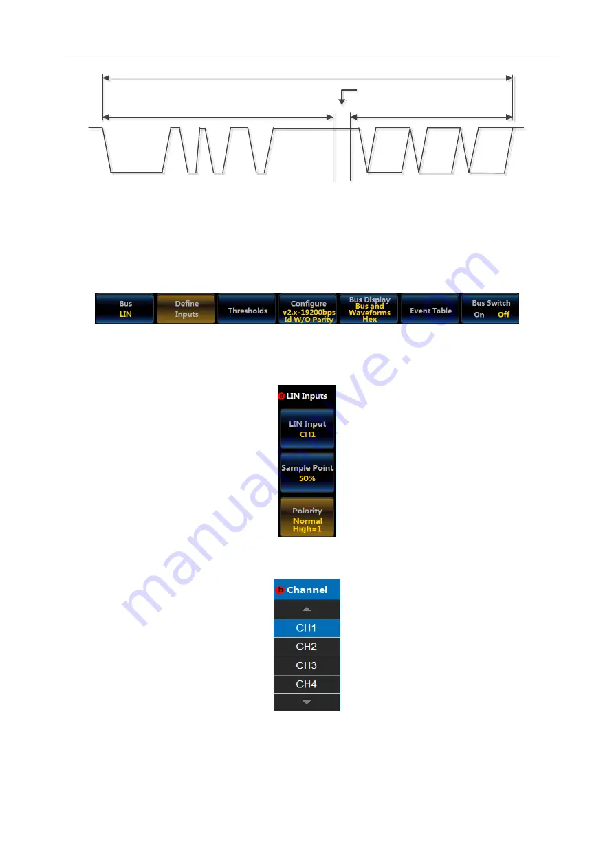
Heade r
Response
space
Response
Frame
Bra ke Field
Sync B yte Fie ld
Identifie r Field
Data1
DataN
Checksum
Field
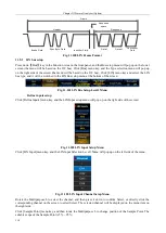
Fig. 11.100 LIN Frame Format
11.5.1 LIN bus setup
Press down
【
Bus
】
key in the Function Area on the front panel, and the Bus setup menu will pop up on the lower
screen (the menu will be based on the I2C bus). Click [Bus] menu key, and the Type selection menu will pop up
on the right side of the screen (the menu will be based on the I2C bus). Click [LIN] menu key and select the LIN
bus type, and it will be switched to the LIN Bus setup menu at the bottom of the screen:
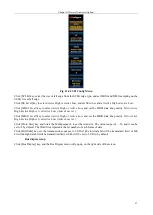
Fig. 11.101 LIN Bus Setup Level1 Menu
Define inputs setup
Click [Define Inputs] menu key, and the LIN Input setup menu will pop up on the right side of the screen:
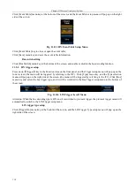
Fig. 11.102 LIN Input Setup Menu
Click [LIN Input] menu key, and the LIN Input Selection Level3 Menu will pop up on the left side of the menu:
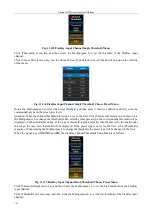
Fig. 11.103 LIN Input Channel Setup Menu
Rotate the Multipurpose b to select the channel, and then press it down to confirm Select, or directly click the
corresponding channel on the screen to select Select. The selected channel will be displayed on the menu item on
the right side.
Click [Sample Point] menu key, and then rotate the Multipurpose b to change position of the Sample Point. The
settable scope of the Sample Point is 5% ~ 95%;
Summary of Contents for 4456 Series
Page 10: ...VIII...
Page 55: ...Chapter V Trigger System 45 Fig 5 51 RF Test Signal Example...
Page 69: ...Chapter VII Mathematical Operation 59 Fig 7 10 Advanced Math Example...
Page 71: ...Chapter VIII Display System 61 Fig 8 3 Wfm Palette Menu Fig 8 4 Normal Palette...
Page 72: ...Chapter VIII Display System 62 Fig 8 5 Inverted Palette Fig 8 6 Temperature Palette...
Page 75: ...Chapter VIII Display System 65 Fig 8 12 XY Display Example...
Page 165: ...Chapter XI Protocol Analyzer Option 155 Fig 11 242 1553 Trigger and Analysis Example...


