


2
Remote Control
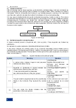
2.1 Remote control basis
5
operating systems to communicate in the network, This method enables two-way communication
between the noise figure analyzer and the computer via port.
The socket is a software class written specifically to define the necessary information for network
communication such as IP address and device port number, and integrates some basic operations in
network programming. Sockets can be used in the operating system installed with a packaged library.
UNIX Berkeley socket and Winsock are commonly used.
The socket in the noise figure analyzer is Berkeley socket and Winsock compatible through the
application program interface (API). In addition, other standard sockets are also compatible through the
API. When the noise figure analyzer is controlled using SCPI command, the socket program created in
the program issues command. Before using the LAN socket, you must set the socket port number of the
noise figure analyzer. The socket port number of the noise figure analyzer is 5000.
2.1.1.2 GPIB interface
The GPIB interface is a widely-used instrument remote interface currently, which can be connected with
different kinds of instruments through the GPIB cable and can establish the test system with the main
control computer. To realize remote control, the main control computer shall be preinstalled with the
GPIB bus card, driver and VISA library. During communication, the main control computer will address
the controlled instrument through the GPIB bus address firstly. The user can set the GPIB address and
ID for querying strings, and the GPIB communication language can be set to the SCPI form by default.
The operation of the GPIB and its relevant interface is defined and described in details in the ANSI/IEEE
standard 488.1-1987 and the ANSI/IEEE standard 488.2-1992. For details of the standard, please refer
to the IEEE website: http://www.ieee.org.
The GPIB processes information in bytes and the data transfer rate can reach 8 MBps. Therefore, the
GPIB data transmission is fast. Since the data transmission speed is limited by the distance between the
device/system and the computer, you need to pay attention to the following matters when you connect
the GPIB:
Up to 15 instruments may be set up through the GPIB interface;
The total length of the transmission cable does not exceed 15 m or does not exceed twice the
number of the instruments in the system. In general, the maximum length of the transmission cables
between devices cannot exceed 2 m.
If you connect multiple instruments in parallel, you need to use “OR” connectors.
The terminal of the IECbus cable shall be connected to the instrument or the controller computer.
2.1.2
Message
Messages transmitted by data cable fall into the following two categories:
1)
Interface message
During communication between the instrument and the main control computer, it is necessary to pull
down the attention line and then the interface message can be transmitted to the instrument through the
data line. Only the instrument with the GPIB bus functions can send the interface message.
2)
Instrument message
For the structure and
syntax of instrument messages, see “5.1.4 SCPIs” for details. The instrument
message can be divided into command and instrument response by transmission direction. Unless
otherwise stated, all remote interfaces should adopt the same method for use of the instrument
message.
a) Commands:
A command (programming message) is a message transmitted from the main control computer to the
instrument for remote control of instrument functions and query of status information. It falls into the
following two categories:
Based on the impact on the instrument:


