


2
Remote Control
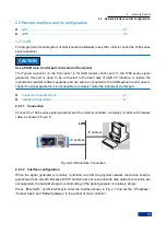
2.1 Remote control basis
20
Positive and negative conversion register
Two transfer registers define the status transfer bit of the condition register stored in the event register.
The positive conversion register is similar to a conversion filter. When an event bit of the condition
register is changed from 0 to 1, the associated PTR bit determines if the event bit should be set to 1, as
described below:
- If the PTR bit is equal to 1, the event bit should be set.
- If the PTR bit is equal to 0, the event bit should not be set.
The positive conversion register is readable and writable, and its reading will not clear any value.
The negative conversion register is similar to a conversion filter. When an event bit of the condition
register is changed from 1 to 0, the associated NTR bit determines if the event bit should be set to 1, as
described below:
- If the NTR bit is equal to 1, the event bit should be set.
- If the NTR bit is equal to 0, the event bit should not be set.
The positive conversion register is readable and writable, and its reading will not clear any value.
Event register
This part indicates whether the event occurs after the last reading, and whether the content of the
condition register is saved. It only represents the event passed by the transfer register and can only be
changed by the instrument, read by the user, and cleared after reading. The value of this part is equal to
the value of whole register generally.
Enable register
This part determines whether the associated event bit acts on the final data sum. The data bit of each
enable part has a And relation with the associated enable bit. The logical operation result of this part has
a OR relation with the data sum bit.
- Enable bit=0: the associated event bit does not act on the data sum.
- Enable bit=1: the associated event bit acts on the data sum.
This part is read-write, and no value will be cleared after reading.
Data bit sum
The data sum bit of each register consists of event and enable parts. The result gets into the condition
part of the high level register. The instrument automatically generates data sum bit for each register so
that events can cause different levels of service requests.
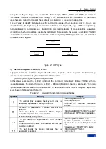
2.1.5.3 Status Register Description
The following describes the status registers in turn, as shown below:
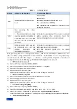
1) Status byte (STB) and service request enable register (SRE)
The IEEE488.2 defines the status byte (STB) that reflects the rough instrument status by collecting
information from the low level registers. The bit6 is equal to the data sum of other status byte bits. The
result after comparing the status byte with the condition part of the SCPI register can be assumed to be
the highest level in the SCPI level. The common command ―*STB?‖ or the serial query can read the
status byte value.
The status byte is connected with the service request enable register (SRE). Each data bit of the status
byte corresponds to one bit in the SRE. The SRE bit6 is ignored. If one data bit in the SRE is set and the
Summary of Contents for 1465 Series
Page 1: ...1465 series Signal Generator Programming Manual...
Page 2: ......
Page 5: ......
Page 39: ......
Page 127: ......


