background image


12   

CET Electric Technology 

Region 

EU 

863-870 

RU 

864-870 

IN 

865-867 

US 

902-928 

AU 

915-928 

AS 

920-923 

AS 

923-925 

Custom 

(Default) 

Channel 0 

863.00   

864.00   

865.00   

902.00   

915.00   

920.00   

923.00 

915.00 

Channel 1 

863.47   

864.41   

865.33   

903.73   

915.87   

920.33   

923.29   

915.33 

Channel 2


863.93   

864.81   

865.66   

905.47   

916.73   

920.66   

923.57   

915.66 

Channel 3


864.40   

865.21   

865.99   

907.20   

917.60   

920.99   

923.86   

915.99 

Channel 4


864.87   

865.61   

866.32   

908.93   

918.47   

921.32   

924.14   

916.32 

Channel 5


865.34   

866.01   

866.65   

910.67   

919.34   

921.65   

924.43   

916.65 

Channel 6


865.80   

866.40   

866.98   

912.40   

920.20   

921.98   

924.71   

916.98 

Channel 7


866.27   

866.80   

867.31   

914.13   

921.07   

922.31   

924.99   

917.31 

Channel 8


866.74   

867.20   

867.64   

915.86   

921.94   

922.64   

920.10   

917.64 

Channel 9


867.20   

867.60   

867.97   

917.60   

922.80   

922.97   

920.46   

917.97 

Channel 10


867.67   

867.99   

868.30   

919.33   

923.67   

923.30   

920.82   

918.30 

Channel 11


868.14   

868.39   

868.63   

921.06   

924.54   

923.63   

921.18   

918.63 

Channel 12


868.60   

868.79   

868.96   

922.80   

925.40   

923.96   

921.54   

918.96 

Channel 13 

869.07   

869.19   

869.29   

924.53   

926.27   

924.29   

921.91   

919.29 

Channel 14 

869.54   

869.59   

869.62   

926.26   

927.14   

924.62   

922.27   

919.62 

Channel 15 

869.99   

869.99   

869.95   

927.99   

927.99   

924.95   

922.63   

919.95 

Table 4-2 16 Channel Assignments 

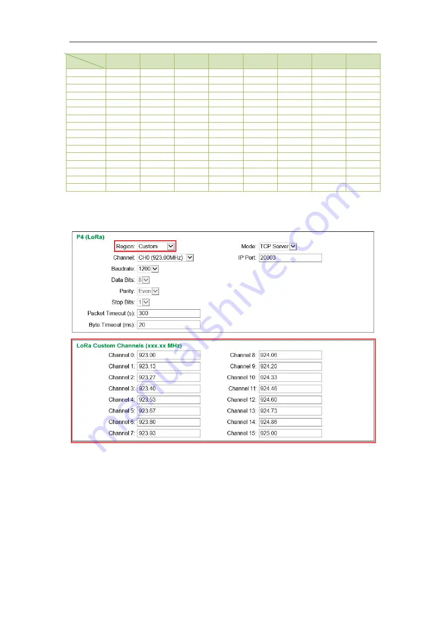
If 

Region 

is set as 

Custom

, the 

LoRa Custom Channels (xxx.xx MHz)

 setup parameters will appear to 

allow the frequencies for the 16 channels to be customized as shown below: 


Figure 4-7 LoRa Custom Channel Settings 

Notes: 

For the 

LoRa Custom Channels (xxx.xx MHz): 

1)


The valid range of Frequency is: 860.00-935.00MHz. Otherwise, the error message “

Channel x: 

Invalid value. Please specify a frequency between 860.00 and 935.00” 

would be shown. 

2)


Up to two decimals can be entered. 

3)


The channel frequency assignment must be unique. Otherwise, the error message “

Channel x: 

Duplicate frequency. Please enter another value.” 

would be shown.   

Channel   

Summary of Contents for PMC-1302-3

Page 1: ...PMC 1302 3 Ethernet Serial LoRa Gateway User Manual Version V1 2 July 3 2020...

Page 2: ...m CET Electric Technology CET The information contained in this Manual is believed to be accurate at the time of publication however CET assumes no responsibility for any errors which may appear here...

Page 3: ...ot accept liability for any damage caused by device malfunctions CET accepts no responsibility for the suitability of the device to the application for which it was purchased Failure to install set up...

Page 4: ...Front Panel LED Indicators 8 3 2 Reset Button 8 3 3 Typical Application 8 Chapter 4 Configuring the PMC 1302 3 ESG via Web Interface 9 4 1 Web Console Login 9 4 2 Ethernet 10 4 3 Serial Port LoRa 10...

Page 5: ...its built in web interface DIN Rail Mount Extended operating temperature 1 3 Applications The PMC 1302 3 ESG supports the efficient transfer of serial packets between the upstream network based appli...

Page 6: ...tion make sure that the DIN rail is already in place Move the installation clip at the back of the PMC 1302 3 downward to the unlock position Align the top of the mounting channel at the back of the P...

Page 7: ...485 communications connections on the PMC 1302 3 ESG Figure 2 5 S485 Communications Connections 2 4 Ethernet Port 10 100BaseT The PMC 1302 3 ESG comes standard with an Ethernet Port P1 using the MDI M...

Page 8: ...P2 is receiving data Yellow Blinking P2 is transmitting data P3 Green Blinking P3 is receiving data Yellow Blinking P3 is transmitting data Table 3 1 LED Indicators 3 2 Reset Button There is a Reset...

Page 9: ...window The Security Settings window appears Enable the three options as shown below and then click OK Figure 4 1 Internet Setting 2 The default IP Address of the PMC 1302 3 ESG s Ethernet Port is 192...

Page 10: ...d P3 and an optional LoRa wireless port P4 All setup parameters such as Baudrate Data Bits Parity Stop Bits IP Port and Timeout can be configured here to match the settings of the downstream RS 485 de...

Page 11: ...1 P3 RS 485 Baudrate 1200 to 38400 bps 9600 Data Bits 8 Parity None Even Odd Stop Bits 1 Packet Timeout s 0 to 60 000s 300s Byte Timeout ms 0 to 60 000ms 20ms Mode TCP Sever TCP Client If the Mode is...

Page 12: ...9 33 923 67 923 30 920 82 918 30 Channel 11 868 14 868 39 868 63 921 06 924 54 923 63 921 18 918 63 Channel 12 868 60 868 79 868 96 922 80 925 40 923 96 921 54 918 96 Channel 13 869 07 869 19 869 29 9...

Page 13: ...4 5 Device Information Click Device Information on the left hand pane and the following screen appears on the right hand pane which includes Model and Information of the PMC 1302 3 Figure 4 9 Device I...

Page 14: ...ot operation has been executed Click Reboot on the left hand pane and the following screen appears on the right hand pane Click the Reboot button to initiate the restart sequence After restart the use...

Page 15: ...C 1302 3 ESG the user can log on to its Web Console page via the Internet Explorer by entering the IP address of the PMC 1302 3 ESG s Ethernet port in the browser s address bar For example type http 1...

Page 16: ...ll perform a reboot operation with the new configuration When the Log In page returns the PMC 1302 3 ESG is now ready Figure 5 4 Reboot Page 5 3 Configuring PecStar iEMS In PecStar iEMS s PecConfig in...

Page 17: ...omm ID to 100 and then click OK to save and exit the dialog box Figure 5 7 Device Node Properties Right click on PMC 660 on the left hand pane click Import SNF file and select the appropriate SNF file...

Page 18: ...Panel LED Indicators Run Green Blinking System is running normally Data Yellow Blinking LoRa is receiving or transmitting data P2 P3 Green Blinking Receiving activity P2 P3 Yellow Blinking Transmittin...

Page 19: ...s EN 61000 4 11 2004 A1 2017 Emission Tests Limits and Methods of Measurement of Electromagnetic Disturbance Characteristics of Industrial Scientific and Medical ISM Radio Frequency Equipment EN 55011...

Page 20: ...20 CET Electric Technology Appendix C Ordering Guide...

Page 21: ...21 CET Electric Technology Contact us CET Electric Technology Inc E sales cet global com W www cet global com...

Reviews: