background image


SmaRT HH-x10 


U089.1.1-SmaRT_HH-x10 

2.0 

Remote Control and Base Unit Communication 

2.1 

Associate HH-xH10 Remote Control to Base Unit 

An HH-x10 remote control unit must establish a communications link with a base unit before it 
can be used for control. An HH-x10 remote (as part of a system) is associated with the system 
base unit before leaving Cervis, Inc. But, it is possible to associate an HH-x10 in the field either 
to address a communication problem or to add or replace a remote control unit. The procedure 
to establish the link is called 

“Association”. 

In situations where it is necessary to establish or re-establish remote control-to-base unit 
communications, use the following steps: 

HH-9H10/2H10 Models: 

1.  Stand near the base unit with the remote control 

OFF

 and 

power removed

 from 

the base unit. 

2.  Push and hold the 

B1

 and 

ON buttons

. All six LEDs light solid. 

3.  Observe the LEDs. When only the 

TX

 LED begins to blink, power up the base 

unit while continuing to hold 

B1

 and 

ON

4.  When all six LEDs light solid, release both buttons. 

HH-9X10 Models: 

1.  Stand near the base unit with the remote control 

OFF

 and 

power removed

 from 

the base unit. 

2.  Push and hold the 

B1

 and 

ON

 buttons for approximately two seconds. The 

A1

A2

, and 

TX

 LEDs light. Release the 

B1

 and 

ON

 buttons. 

3.  Press and hold button 

B1

. Turn base unit power on. Release button 

B1

 when 

base unit powers up. 

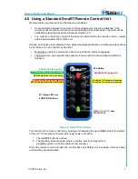
The remote control and base unit are connected when both the 

TX

 and 

RX

 LEDs on both 

devices start blinking simultaneously as messages pass between them. The SmaRT system is 
ready for use. 


Figure 3. Associate an HH-x10 Remote Control to a Base Unit 

Hold to ASSOCIATE 

TX 

RX 

B1 

B2 

Hold to 

ASSOCIATE 

BAT 

ERR 

Summary of Contents for HH-2H10B

Page 1: ... 2019 Cervis Inc HH x10 Remote Control Unit Manual DN U089 1 1 SmaRT_HH x10 ...

Page 2: ...site https www canada ca en health canada services environmental workplace health reports publications radiation safety code 6 health canada radiofrequency exposure guidelines environmental workplace health health canada html Le présent appareil est conforme à la norme CNR 210 d Industrie Canada Le programme d installation de cet équipement radio doit s assurer que l antenne est située ou fait tel...

Page 3: ...tion of established communication links between remote control units and base units involved in the process Line of Sight aka Direct Line of Sight Type of communication between transceivers or a transmitter and a receiver where the pathway between the two units must be clear of obstacles TX RX Transmit Receive Document Conventions Note Notes are used to indicate points of interest or pertinent inf...

Page 4: ...down 8 6 0 Specifications 9 7 0 Spare Parts List 10 Appendix A Exposure to Radio Frequency Energy 11 Appendix B Agency Identification Label Locations 11 List of Figures Figure 1 HH x10 6 LED Remote Control Button Assignments 2 Figure 2 Standard Ten Button Example 3 Figure 3 Associate an HH x10 Remote Control to a Base Unit 4 Figure 4 Dissociate an HH x10 Remote control from a Base Unit 5 Figure 5 ...

Page 5: ...ng Do not activate the remote control system until you are certain that it is safe to do so Turn off the remote control and disconnect power from the base unit before attempting any maintenance This will prevent accidental operation of the controlled machinery Power can safely be disconnected from the remote by removing the source power batteries from the unit Power can be removed from the base un...

Page 6: ...turns itself off to conserve power if no function buttons are pushed Figure 1 HH x10 6 LED Remote Control Button Assignments The HH x10 remote control can communicate with a wide variety of SmaRT base units using direct sequence spread spectrum DSSS wireless technology at 2 4GHz or 900MHz A standard HH x10 offers up to ten command functions and up to twenty command functions with the dual use of t...

Page 7: ...s An example of a custom programmed HH x10 is shown as the center unit in Figure 1 HH x10 Remote Control Remote Options The HH x10 can be ordered with or without a belt clip Table 1 lists the available models Table 1 HH x10 Remote control Options Model Name Frequency RF Power Activation Deactivation Belt Clip HH 9H10 900MHz 10mW ON OFF NO HH 9H10B 900MHz 10mW ON OFF YES HH 2H10 2 4GHz 100mW ON OFF...

Page 8: ... unit with the remote control OFF and power removed from the base unit 2 Push and hold the B1 and ON buttons All six LEDs light solid 3 Observe the LEDs When only the TX LED begins to blink power up the base unit while continuing to hold B1 and ON 4 When all six LEDs light solid release both buttons HH 9X10 Models 1 Stand near the base unit with the remote control OFF and power removed from the ba...

Page 9: ...s light solid 3 Observe the LEDs When only the TX LED begins to blink power up the base unit while continuing to hold B2 and ON 4 When all six LEDs light solid release both buttons HH 9X10 Models 1 Stand near the base unit with the remote control OFF and power removed from the base unit 2 Push and hold the B2 and ON buttons for approximately two seconds The A1 A2 and TX LEDs light Release buttons ...

Page 10: ...position the batteries as illustrated in Figure 5 below 3 If replacing expired batteries remove the old batteries and install two fresh size AAA cell batteries Discard the used batteries according to local regulations Be sure to position the batteries as illustrated in Figure 5 below 4 Replace the compartment cover and tighten the four Phillips screws Do not over tighten these screws but make sure...

Page 11: ... button is engaged Latched where once pushed the output or function remains active when the button is released Figure 6 HH x10 Front Panel Turn the HH x10 remote control on by pushing and releasing the green ON button at the bottom of the unit The remote control remains under power until either 1 The red OFF button is pushed 2 The Inactivity timeout occurs where no button activity is sensed for a ...

Page 12: ...Be aware that you can easily miss this brief time Once the remote control automatically shuts down the unit will not function properly until a fresh set of two AAA cell batteries are installed Figure 7 HH x10 Remote Low Battery Warning and Auto Shutdown LOW BATTERY The BAT LED begins flashing once per second indicating that a LOW BATTERY 2 1V or less condition is present Two fresh AAA cell batteri...

Page 13: ...Frequency 906 924MHz 10mW HH 9H10 906 924MHz 100mW HH 9X10 2405 2480MHz 100mW HH 2H10 License None required Modulation DSSS Antenna Internal Enclosure Dimensions mm 136 38 x 68 96 x 28 42 inches 5 37 x 2 68 x 0 92 Total Weight 200g 7 2 oz with lanyard or belt clip Durability High Impact Polymer case Polycarbonate faceplate Impact absorbing bumper LED Indicators TX Green Transmit Flashes when trans...

Page 14: ...st Table 3 Spare Parts List Item Cervis Inc Bin Location Protective Rubber Bumper AA6 02 Lanyard AA8 01B Battery Cover with 4 Attached Screws Call Cervis Inc 724 741 9000 AAA 1 5V Cell Batteries Two pack AA6 03 Belt Clip AA5 07 Replacement Antenna Disallowed ...

Page 15: ...commended guidelines always follow these instructions and precautions When using the handheld remote control unit Hold the remote so that the top buttons are away from the body in the direction of the base unit Keep the remote at least 15mm inch away from the body Only use carrying cases belt clips or holders approved by the Cervis Inc Appendix B Agency Identification Label Locations Figure 8 Agen...

Page 16: ...SmaRT HH x10 U089 1 1 SmaRT_HH x10 12 Visit our Web site at www cervisinc com 2019 Cervis Inc All rights reserved Content is subject to change without notice ...

Reviews: