background image

User Guide for FibeAir® IP-20 All-Outdoor Products, CeraOS 10.5 


Page 365 of 825 


Ceragon Proprietary and Confidential


When configuring the outgoing clock and SSM administration, the Sync mode 
must be set to its default setting of automatic. To display the current Sync mode, 
enter the following CLI command in root view: 

root> platform sync mode show 

If the Sync mode is set to pipe, you must set it to automatic by entering the 
following CLI command in root view: 

root> platform sync mode set automatic 

To configure the outgoing clock on an Ethernet interface, the Media Type of the 
interface must be RJ45 or SFP, 

not

 Auto-Type. To view and configure the Media 

Type of an Ethernet interface, see 

Configuring Ethernet Interfaces

. 

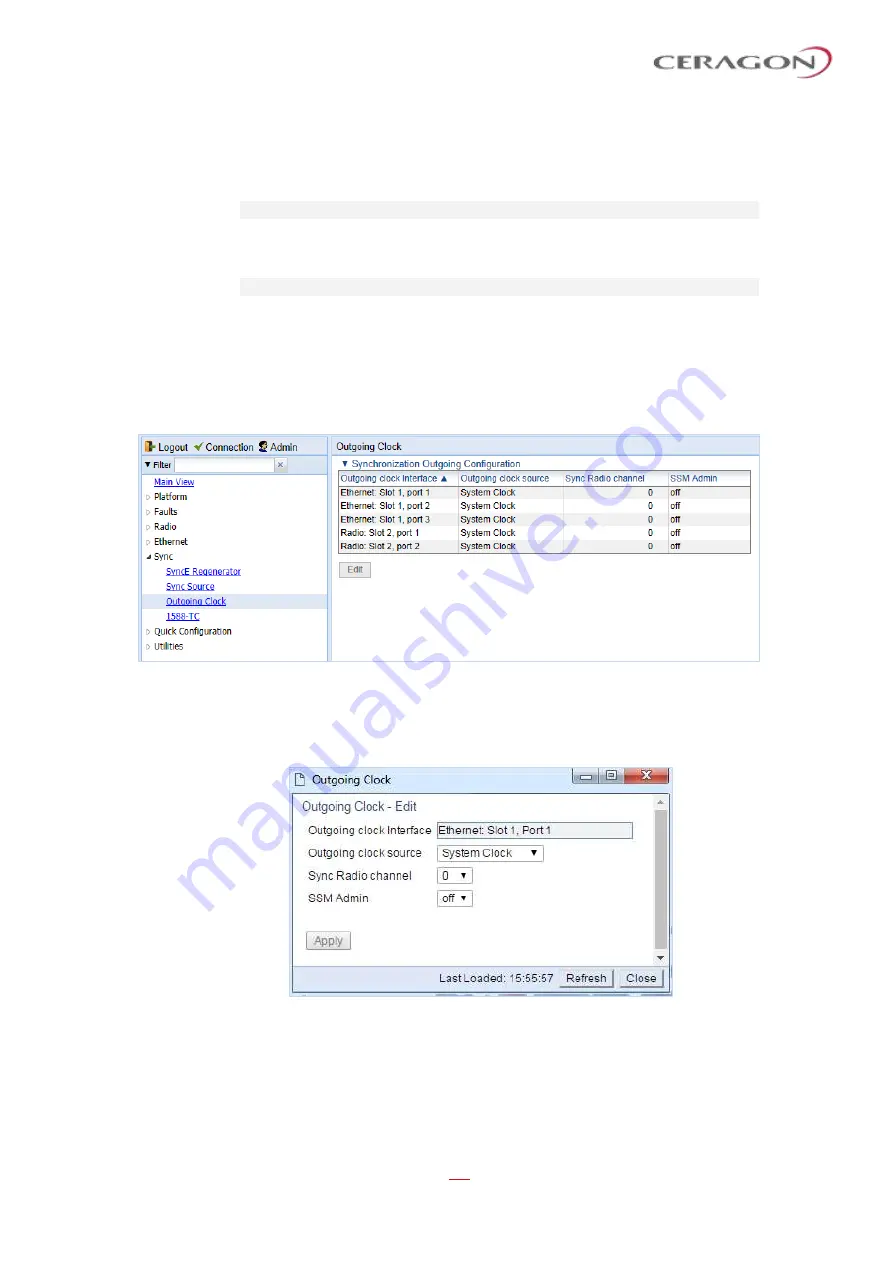
To view and configure the synchronization parameters of the unit’s interfaces:


1  Select 

Sync > Outgoing Clock

. The Outgoing Clock page opens. 


Figure 281: Outgoing Clock Page 

2  Select the interface you want to configure and click 

Edit

. The Outgoing Clock 


Edit page opens.  


Figure 282: Outgoing Clock 

 Edit Page 

3  In the 

Outgoing clock source

 field, select the interface's synchronization 

source. Options are:  


Local Clock


 The interface uses its internal clock as its synchronization 

source. 

Summary of Contents for FibeAir IP-20 All-Outdoor Series

Page 1: ...User Guide FibeAir IP 20 All Outdoor Products IP 20C IP 20C HP IP 20S IP 20E IP 20V December 2018 Rev S 02 CeraOS 10 5 Copyright 2018 by Ceragon Networks Ltd All rights reserved ...

Page 2: ...e Product may use open source software among them O S software released under the GPL or GPL alike license Open Source License Inasmuch that such software is being used it is released under the Open Source License accordingly The complete list of the software being used in this product including their respective license and the aforementioned public available changes is accessible at Network eleme...

Page 3: ...ure 58 Section II Web EMS Configuration 64 2 Getting Started 65 2 1 Assigning IP Addresses in the Network 65 2 2 Establishing a Connection 65 2 2 1 PC Setup 66 2 3 Logging on 67 2 3 1 Logging in Without Knowing the IP Address 67 2 4 Changing Your Password 69 2 5 Applying a Pre Defined Configuration File 70 2 6 Performing Quick Platform Setup 72 2 7 Mate Management Access IP Forwarding 75 2 8 Confi...

Page 4: ...2 4 Configuring a Multiband Enhanced Multi Carrier ABC Link Using the Quick Configuration Wizard 121 3 3 Configuring Multi Carrier ABC 128 3 3 1 Multi Carrier ABC Overview 128 3 3 2 Configuring a Multi Carrier ABC Group 128 3 3 3 Configuring the Multi Carrier ABC Minimum Bandwidth Override Option 130 3 3 4 Adding and Removing Group Members 131 3 3 5 Deleting a Multi Carrier ABC Group 132 3 4 Confi...

Page 5: ...7 Deleting a MIMO or Space Diversity Group 183 3 10 Configuring Advanced Frequency Reuse AFR 184 3 10 1 AFR Overview 184 3 10 2 Initial Link Configuration and Alignment for AFR 185 3 10 3 Software Configuration for AFR 185 3 10 4 Deleting an AFR Group 189 3 11 Operating an IP 20C or IP 20C HP in Single Radio Carrier Mode 190 4 Unit Management 191 4 1 Defining the IP Protocol Version for Initiating...

Page 6: ...ying Current BER 244 5 6 2 Displaying MRMC Status 246 5 6 3 Displaying MRMC PMs 247 5 6 4 Displaying and Clearing Defective Block Counters 248 5 6 5 Displaying Signal Level PMs and Configuring Signal Level PM Thresholds 250 5 6 6 Displaying Modem BER Aggregate PMs 252 5 6 7 Displaying MSE PMs and Configuring MSE PM Thresholds 253 5 6 8 Displaying XPI PMs and Configuring XPI PM Thresholds 255 5 6 9...

Page 7: ...4 2 Enabling Marking 314 7 4 3 Modifying the 802 1Q Marking Table 315 7 4 4 Modifying the 802 1AD Marking Table 316 7 5 Configuring WRED 318 7 5 1 WRED Overview 318 7 5 2 Configuring WRED Profiles 318 7 5 3 Assigning WRED Profiles to Queues 321 7 6 Configuring Egress Shaping 322 7 6 1 Egress Shaping Overview 322 7 6 2 Configuring Queue Shaper Profiles 322 7 6 3 Configuring Service Bundle Shaper Pr...

Page 8: ...al Access Control Parameters 371 10 2 Configuring the Password Security Parameters 373 10 3 Configuring the Session Timeout 374 10 4 Configuring Users 375 10 4 1 User Configuration Overview 375 10 4 2 Configuring User Profiles 375 10 4 3 Configuring Users 378 10 5 Configuring RADIUS 379 10 5 1 RADIUS Overview 380 10 5 2 Activating RADIUS Authentication 380 10 5 3 Configuring the RADIUS Server Attr...

Page 9: ... CLI 445 13 3 Logging On CLI 445 13 4 General CLI Commands 446 13 5 Changing Your Password CLI 447 13 6 Mate Management Access IP Forwarding CLI 448 13 7 Configuring In Band Management CLI 450 13 8 Changing the Management IP Address CLI 450 13 9 Configuring the Activation Key CLI 452 13 9 1 Activation Key Overview CLI 452 13 9 2 Viewing the Activation Key Status Parameters CLI 452 13 9 3 Entering ...

Page 10: ...iband Node CLI 474 14 3 5 Deleting a Multiband Group CLI 474 14 3 6 Displaying Multiband Group Statistics CLI 474 14 4 Configuring Link Aggregation LAG and LACP Optional CLI 475 14 4 1 LAG Overview CLI 475 14 4 2 Configuring a LAG Group CLI 476 14 4 3 Configuring LACP CLI 476 14 4 4 Viewing LAG Details CLI 477 14 4 5 Editing and Deleting a LAG Group CLI 477 14 4 6 Enabling and Disabling the LAG Gr...

Page 11: ...505 15 1 Defining the IP Protocol Version for Initiating Communications CLI 505 15 2 Configuring the Remote Unit s IP Address CLI 505 15 2 1 Configuring the Remote Radio s IP Address in IPv4 format CLI 505 15 2 2 Configuring the Remote Radio s IP Address in IPv6 format CLI 506 15 3 Configuring SNMP CLI 508 15 3 1 Configuring Basic SNMP Settings CLI 508 15 3 2 Configuring SNMPv3 CLI 510 15 3 3 Disp...

Page 12: ...6 1 Displaying General Modem Status and Defective Block PMs CLI 543 16 6 2 Displaying Excessive BER Aggregate PMs CLI 543 16 6 3 Displaying BER Level and Configuring BER Parameters CLI 545 16 6 4 Configuring RSL Thresholds CLI 545 16 6 5 Configuring TSL Thresholds CLI 546 16 6 6 Displaying RSL and TSL Levels CLI 546 16 6 7 Configuring the Signal Level Threshold CLI 548 16 6 8 Configuring the MSE T...

Page 13: ...Classification CLI 611 18 1 7 Configuring a Default CoS CLI 613 18 1 8 Configuring Ingress Path Classification on a Service Point CLI 613 18 1 9 Configuring Ingress Path Classification on a Service CLI 613 18 2 Configuring Policers Rate Metering CLI 614 18 2 1 Overview of Rate Metering Policing CLI 614 18 2 2 Configuring Rate Meter Policer Profiles CLI 614 18 2 3 Displaying Rate Meter Profiles CLI...

Page 14: ... the LLDP Remote System Parameters CLI 663 19 2 7 Displaying LLDP Statistics CLI 665 20 Synchronization CLI 668 20 1 Configuring SyncE Regenerator CLI 668 20 2 Changing the ETSI ANSI Mode CLI 670 20 3 Configuring the Sync Source CLI 670 20 3 1 Configuring an Ethernet Interface as a Synchronization Source CLI 671 20 3 2 Configuring a Radio Interface as a Synchronization Source CLI 672 20 3 3 Cleari...

Page 15: ...nt and Troubleshooting CLI 701 22 1 Viewing Current Alarms CLI 701 22 2 Viewing the Event Log CLI 701 22 3 Editing Alarm Text and Severity CLI 701 22 3 1 Displaying Alarm Information CLI 703 22 3 2 Editing an Alarm Type CLI 703 22 3 3 Setting Alarms to their Default Values CLI 703 22 4 Configuring a Timeout for Trap Generation CLI 704 22 5 Disabling Alarms and Events CLI 705 22 6 Configuring Volta...

Page 16: ...t FE Interface RJ 45 LEDs 740 23 6 4 Radio LED 741 23 6 5 Status LED 741 23 6 6 Protection LED 741 23 7 IP 20S Connector Pin outs 742 23 7 1 Eth1 PoE GbE Electrical PoE Optical 743 23 7 2 Eth2 GbE Electrical Optical 743 23 7 3 Eth3 GbE Electrical Optical 743 23 7 4 MGT PROT Management FE Standard and Protection FE Non Standard 744 23 7 5 DC 744 23 7 6 RSL Interface 744 23 8 IP 20S LEDs 745 23 8 1 ...

Page 17: ...23 10 8 Protection LED 754 23 11 IP 20V Connector Pin outs 755 23 11 1 Eth2 Eth3 GbE Optical Interface SFP CSFP 755 23 11 2 Eth1 10GE Optical Interface SFP 755 23 11 3 MGT GbE Electrical Interface RJ 45 756 23 11 4 Power Adaptor 756 23 11 5 RSL Interface 756 23 12 IP 20V LEDs 758 23 12 1 Eth1 10GE Optical Interface SFP LEDs 758 23 12 2 Eth2 Eth3 GbE Optical Interface SFP CSFP LEDs 758 23 12 3 MGT ...

Page 18: ... From File Page 71 Figure 17 Quick Configuration From File Page Configuration File Loaded 71 Figure 18 Quick Configuration Platform Setup Page 72 Figure 19 Quick Configuration Platform Setup Summary Page 74 Figure 20 Local Networking Configuration Page 76 Figure 21 Activation Key Configuration Page 78 Figure 22 Activation Key Overview Page 81 Figure 23 Time Services Page 82 Figure 24 Interface Man...

Page 19: ...ard Radio 2 Selection Page 116 Figure 54 2 0 Multi Carrier ABC Quick Configuration Wizard Radio XPIC Configuration Page 116 Figure 55 2 0 Multi Carrier ABC Quick Configuration Wizard Radio Parameters Configuration Page 117 Figure 56 2 0 Multi Carrier ABC Quick Configuration Wizard Radio Parameters Configuration Page XPIC 117 Figure 57 2 0 Multi Carrier ABC Quick Configuration Wizard Radio MRMC Scr...

Page 20: ...e 87 Multiband Configuration with Inband Management and or SyncE via the IP 20E 141 Figure 88 Multiband Configuration with Direct Inband Management to the IP 20C or IP 20S 142 Figure 89 Multiband Configuration with Direct Inband Management to the IP 20C or IP 20S 143 Figure 90 Create LAG Group Page 1 146 Figure 91 Create LAG Group Page 2 147 Figure 92 Create LAG Group Final Page 147 Figure 93 Link...

Page 21: ...bers Page 182 Figure 124 Diversity Groups Edit Members Page 182 Figure 125 AFR 1 0 Deployment 184 Figure 126 AFR 1 0 Configuration 185 Figure 127 Advanced Multi Carrier Configuration Page Empty 186 Figure 128 AMCC Group Select Group Parameters Page 186 Figure 129 AMCC Group Select Members Parameters Page Hub Site 187 Figure 130 AMCC Group Select Members Parameters Page Tail Site 187 Figure 131 AMC...

Page 22: ...er IP 20C IP 20C HP 227 Figure 164 Remote Radio Parameters Page IP 20C IP 20C HP 229 Figure 165 Remote Radio Parameters Page IP 20S IP 20E and IP 20V 229 Figure 166 Remote Radio Parameters Page Per Carrier Multi Carrier 230 Figure 167 ATPC Page IP 20C IP 20C HP 232 Figure 168 ATPC Edit Page Per Carrier IP 20C IP 20C HP 232 Figure 169 Radio Ethernet Interface Configuration Page IP 20C IP 20C HP 234...

Page 23: ...Figure 198 Multiple Selection Operation Section Ethernet Services 268 Figure 199 Ethernet Service Points Page 270 Figure 200 Ethernet Service Points Page Ingress Attributes 272 Figure 201 Ethernet Service Points Page Egress Attributes 274 Figure 202 Ethernet Service Points Add Page 276 Figure 203 Attached VLAN List Page 278 Figure 204 Attached VLAN List Add Page 278 Figure 205 Ethernet General Con...

Page 24: ... 312 Figure 236 Logical Interfaces Policers Page Ethertype Policer 313 Figure 237 802 1Q Marking Page 315 Figure 238 802 1Q Marking Edit Page 315 Figure 239 802 1AD Marking Page 316 Figure 240 802 1AD Marking Edit Page 316 Figure 241 WRED Profile Page 319 Figure 242 WRED Profile Add Page 319 Figure 243 Logical Interfaces WRED Page 321 Figure 244 Logical Interfaces WRED Edit Page 321 Figure 245 Que...

Page 25: ... 351 Figure 271 LLDP Local System Port Page 353 Figure 272 LLDP Local System Management Page 354 Figure 273 LLDP Local System Management View Page 354 Figure 274 LLDP Statistic Page 355 Figure 275 LLDP Port TX Statistics Page 356 Figure 276 LLDP Port RX Statistics Page 357 Figure 277 SyncE Regenerator Page 360 Figure 278 Pipe Configurations Add Page 360 Figure 279 Sync Source Page 362 Figure 280 S...

Page 26: ...licy Adding Vendor Specific Attributes 394 Figure 310 Create Network Policy Selecting to Add Attribute Information 394 Figure 311 Create Network Policy Specifying the Vendor 395 Figure 312 Create Network Policy Configuring Vendor Specific Attribute Information 396 Figure 313 Create Network Policy Example of Vendor Specific Attribute Configuration 397 Figure 314 Create Network Policy Stopping Start...

Page 27: ...gure 346 Add SOAM MEP Wizard Summary Page 432 Figure 347 SOAM MEP Edit Page 434 Figure 348 SOAM MEP DB Table 435 Figure 349 MEP Last Invalid CCMS Page 436 Figure 350 SOAM MEP Loopback Page 438 Figure 351 Restart HTTP Page 440 Figure 352 ifIndex Calculator Page 441 Figure 353 MIB Reference Table Page 441 Figure 354 IP 20C Interfaces Descriptive Labels 732 Figure 355 IP 20C Interfaces Letter Labels ...

Page 28: ...or FibeAir IP 20 All Outdoor Products CeraOS 10 5 Page 28 of 825 Ceragon Proprietary and Confidential Figure 368 Two Wire to PoE Port Power Adaptor 756 Figure 369 RSL Pins 757 Figure 370 PoE Injector Connectors 760 ...

Page 29: ...Symmetrical Scripts Page Parameters 91 Table 14 Available Radio Profiles IP 20C IP 20C HP and IP 20S 92 Table 15 Available Radio Profiles IP 20E 92 Table 16 Available Radio Profiles IP 20V 93 Table 17 System Configurations 105 Table 18 Multiband Cable for Use with CSFP Port 140 Table 19 LACP Aggregation Status Parameters 151 Table 20 LACP Port Status Parameters 153 Table 21 LACP Port Statistics 15...

Page 30: ...le 53 Ethernet RX Port PMs 294 Table 54 Logical Interface Classification Parameters 300 Table 55 Policer Profile Parameters 309 Table 56 ABN Status Parameters 340 Table 57 ABN Entity Statistics Parameters 341 Table 58 LLDP Remote System Management Parameters 343 Table 59 LLDP Read Only Configuration Parameters 344 Table 60 LLDP Configurable Configuration Parameters 345 Table 61 LLDP Port Configura...

Page 31: ...TX Frequency CLI Parameters 462 Table 90 Radio Transmit TX Level CLI Parameters 463 Table 91 System Configurations CLI 468 Table 92 LAG Group CLI Parameters 477 Table 93 LACP Aggregation Status Parameters CLI 481 Table 94 LACP Port Status Parameters CLI 482 Table 95 LACP Port Statistics CLI 484 Table 96 MMI and XPI Levels CLI Parameters 499 Table 97 Remote Unit IP Address IPv4 CLI Parameters 506 T...

Page 32: ...rnet Service Operational State CLI Parameters 560 Table 130 Ethernet Service CoS Mode CLI Parameters 561 Table 131 Ethernet Service EVC CLI Parameters 562 Table 132 Deleting Ethernet Service CLI Parameters 563 Table 133 Service Points per Service Type 564 Table 134 Service Point Types per Interface 565 Table 135 Legal Service Point Interface Type Combinations per Interface SAP and SNP 566 Table 13...

Page 33: ... CLI Parameters 599 Table 165 Ethernet Port PMs 601 Table 166 VLAN Classification and Override CLI Parameters 604 Table 167 802 1p Trust Mode CLI Parameters 606 Table 168 C VLAN 802 1 UP and CFI Bit Classification Table Default Values 606 Table 169 C VLAN 802 1 UP and CFI Bit Classification Table CLI Parameters 607 Table 170 S VLAN 802 1 UP and DEI Bit Classification Table Default Values 608 Table...

Page 34: ...riority Profile CLI Parameters 638 Table 200 Interface Priority Sample Profile Parameters 639 Table 201 Attaching Priority Profile to Interface CLI Parameters 640 Table 202 WFQ Profile Example 641 Table 203 WFQ Profile CLI Parameters 642 Table 204 WFQ Sample Profile Parameters 642 Table 205 Attaching WFQ Profile to Interface CLI Parameters 643 Table 206 Egress Queue Level PMs CLI Parameters 644 Ta...

Page 35: ...e 237 Radio Loopback CLI Parameters 712 Table 238 Ethernet Loopback CLI Parameters 713 Table 239 Maintenance Domain CLI Parameters 715 Table 240 SOAM MEG CLI Configuration Parameters 717 Table 241 MEP CLI Configuration Parameters 720 Table 242 MEP and Remote MEP Status Parameters CLI 722 Table 243 Loopback CLI Parameters 727 Table 244 CW Mode CLI Parameters 728 Table 245 IP 20C Eth1 PoE Interface ...

Page 36: ...ibeAir IP 20 All Outdoor Products CeraOS 10 5 Page 36 of 825 Ceragon Proprietary and Confidential Table 259 PoE Injector RJ 45 Data Port Supporting 10 100 1000Base T 760 Table 260 Alarms 763 Table 261 Abbreviations 819 ...

Page 37: ...c Fields Exposure to strong high frequency electromagnetic fields may cause thermal damage to personnel The eye cornea and lens is easily exposed Any unnecessary exposure is undesirable and should be avoided In radio relay communication installations ordinary setup for normal operation the general RF radiation level will be well below the safety limit In the antennas and directly in front of them ...

Page 38: ...st be disconnected from the transmitter before it is disconnected from the receiver When the cable is reconnected it must be connected to the receiver before it is connected to the transmitter Special Requirements for North America Grounding This equipment is designed to permit connection between the earthed conductor of the DC supply circuit and the earthing conductor at the equipment Note This e...

Page 39: ...Equipment connected to the protective earthing of the building installation through the mains connection or through other equipment with a connection to protective earthing and to a cable distribution system using coaxial cable may in some circumstances create a fire hazard Connection to a cable distribution system has therefore to be provided through a device providing electrical isolation below ...

Page 40: ...aut débrancher toutes les alimentations électriques Bruit de machine d ordre 3 GPSGV le plus haut niveau de pression sonore s élève à 70 dB A au maximum dans le respect de la norme ISO EN 7779 Allgemeine Vorsichtsmaßnahmen für die Anlage Wenn andere Steuerelemente verwendet Einstellungen vorgenommen oder Verfahren durchgeführt werden als die hier angegebenen kann dies gefährliche Strahlung verursa...

Page 41: ...Information Products Declaration of Hazardous Toxic Substances Component Lead Pb Mercury Hg Cadmium Cd Hexavalent Chromium Cr VI Polybrominated Biphenyls PBB Polybrominated Diphenyl Ethers PBDE PCB Circuit Modules Comply Comply Comply Comply Comply Comply Mechanical Parts Comply Comply Comply Comply Comply Comply Cables Comply Comply Comply Comply Comply Comply ...

Page 42: ...s manual may not be available in the current release Please consult the Release Notes for the functionality supported in the specific release you are using Target Audience This manual is intended for use by individuals responsible for configuration and administration of an IP 20 system or network Related Documents FibeAir IP 20C Technical Description FibeAir IP 20C Installation Guide FibeAir IP 20...

Page 43: ...User Guide for FibeAir IP 20 All Outdoor Products CeraOS 10 5 Page 43 of 825 Ceragon Proprietary and Confidential Section I Introduction ...

Page 44: ... FibeAir IP 20 Assured Platform The Web Based Element Management System This user manual provides instructions for configuring and operating the following products IP 20C IP 20C HP IP 20S IP 20E IP 20V Each of these products except IP 20C HP can be used with a Ceragon approved PoE Injector Wherever applicable the manual notes the specific distinctions between these products The manual also notes w...

Page 45: ...ype of the interface must be RJ 45 or SFP not Auto Type See Synchronization In Band Management In order to use in band management with an external switch it must be supported on the external switch When configuring in band management be sure to tag the management traffic to avoid overflow of the CPU For instructions on configuring in band management on the IP 20 see Configuring In Band Management ...

Page 46: ...equency band It is the diplexer unit which is passive that determines the sub band coverage for the entire integrated IP 20C HP unit This provides operators with major benefits in terms of both maintenance and deployment time For maintenance the operator can reduce the number of spare radio units in its inventory because a single generic radio unit can be used for any sub band This means that for ...

Page 47: ...ns in interface layout and capacity For a full description of these options refer to the Technical Description for FibeAir IP 20E For purposes of this document when it is necessary to distinguish between different IP 20E R2H hardware models the following terms are used IP 20E R2H ESP Includes all IP 20E R2 models that support a 10GE interface and include ESP in their marketing models IP 20E R2H Al...

Page 48: ...h data and the DC power supply to the IP 20C IP 20S IP 20E or IP 20V unit To do so the PoE injector combines 48VDC input and GbE signals via a standard CAT5E cable using a proprietary Ceragon design The PoE injector can be ordered with a DC feed protection and with 24VDC support as well as EMC surge protection for both indoor and outdoor installation options It can be mounted on poles walls or ins...

Page 49: ...th FIPS 140 2 specifications for cryptography module FIPS 140 2 Level 2 physical security AES 256 encryption FIPS 197 over radio links The FibeAir IP 20 Assured platform also provides Secured communication and protocols for management interface Centralized user authentication management via RADIUS Advanced identity management and password policy enforcement Security events log Secure product archi...

Page 50: ...e updates Security Configuration Enables you to configure security features User Management Enables you to define users and user groups The Web EMS opens to a page that summarizes the key unit parameters The next page when scrolling down the Web EMS main menu summarizes the key radio parameters See The Unit Summary Page and The Radio Summary Page A Web Based EMS connection to the unit can be opene...

Page 51: ...eb EMS Page Layout Each Web EMS page includes the following sections The left section of the page displays the Web EMS menu tree Click to display the sub options under a menu item Click to hide the sub options under a menu item The main section of the page provides the page s basic functionality Figure 1 Main Web EMS Page ...

Page 52: ...ly you can display a representation of the IP 20 front panel by clicking either the arrow in the center or the arrow at the right of the bottom toolbar Figure 2 Displaying a Representation of the Front Panel Figure 3 Main Web EMS Page with Representation of Front Panel IP 20C and IP 20S Figure 4 Main Web EMS Page with Representation of Front Panel IP 20C HP ...

Page 53: ...en HSB radio protection is enabled two tabs appear on the top of the main section These tabs are labeled Active and Standby and enable you to configure the Active and Standby units separately if necessary The title above the main section indicates whether you are working with the Active or Standby TCC For details on configuring HSB radio protection see Configuring Unit Protection with HSB Radio Pr...

Page 54: ...e 7 Main Web EMS Page with Active and Standby Tabs 1 9 2 3 Related Pages Drop Down List Certain pages include a Related Pages drop down list on the upper right of the main section of the page You can navigate to a page related to the current page by selecting the page from this list Figure 8 Related Pages Drop Down List ...

Page 55: ...guring Unit Parameters Current Alarms All alarms currently raised on the unit For additional information see Viewing Current Alarms The Unit Summary page can be customized to include only specific columns and tables This enables you to hide information you do not need in order to focus on the information that is most relevant To hide a specific section of the Unit Summary page click the section ti...

Page 56: ...meters Key information about the status of the remote carrier For additional information see Configuring the Remote Radio Parameters Radio Transmitter Mute status maximum and operational TX level modulation and bit rate For additional information see Configuring the Radio Parameters Radio Receiver Receiver PMs and statistics including defective blocks modem MSE and RX level modulation and bit rate...

Page 57: ...User Guide for FibeAir IP 20 All Outdoor Products CeraOS 10 5 Page 57 of 825 Ceragon Proprietary and Confidential Figure 12 Radio Summary Page Customizing Columns ...

Page 58: ...ring NTP Management Time Services Setting the Time and Date Optional Management Inventory Displaying Unit Inventory Management Unit Info Uploading Unit Info Management Networking Local Changing the Management IP Address Defining the IP Protocol Version for Initiating Communications Management Networking Remote Configuring the Remote Unit s IP Address Management SNMP SNMP Parameters Configuring SNM...

Page 59: ...ng RADIUS Security Access Control Radius Radius Users Viewing RADIUS User Permissions and Connectivity Security Protocols Control Configuring the Session Timeout Blocking Telnet Access Table 3 IP 20 Web EMS Menu Hierarchy Faults Menu Sub Menus For Further Information Current alarms Viewing Current Alarms Alarm Statistics Viewing Alarm Statistics Event Log Viewing and Saving the Event Log Alarm Con...

Page 60: ...SE PMs PM Statistics XPI Displaying XPI PMs and Configuring XPI PM Thresholds PM Statistics MRMC Displaying MRMC PMs PM Statistics Traffic Capacity Throughput Displaying Capacity and Throughput PMs PM Statistics Traffic Utilization Displaying Utilization PMs PM Statistics Traffic Frame error rate Displaying Frame Error Rate PMs Diagnostics Loopback Performing Radio Loopback Groups XPIC Configuring...

Page 61: ... Classification 802 1Q Modifying the C VLAN 802 1Q UP and CFI Bit Classification Table QoS Classification 802 1AD Modifying the S VLAN 802 1 UP and DEI Bit Classification Table QoS Classification DSCP Modifying the DSCP Classification Table QoS Classification MPLS Modifying the MPLS EXP Bit Classification Table QoS Policer Policer Profile Configuring Policer Profiles QoS Marking 802 1Q Modifying t...

Page 62: ...System Management Displaying the Local Unit s Parameters Protocols LLDP Advanced Statistic General Displaying LLDP Statistics Protocols LLDP Advanced Statistic Port TX Displaying LLDP Statistics Protocols LLDP Advanced Statistic Port RX Displaying LLDP Statistics Protocols SOAM MD Configuring Service OAM SOAM Fault Management FM Protocols SOAM MA MEG Configuring Service OAM SOAM Fault Management F...

Page 63: ...guration Menu Sub Menus For Further Information From File Applying a Pre Defined Configuration File Platform Setup Performing Quick Platform Setup PIPE 1 0 Configuring a 1 0 Link Using the Quick Configuration Wizard PIPE 1 0 Repeater Configuring a 1 0 Repeater Link Using the Quick Configuration Wizard PIPE Multi Carrier ABC 2 0 Configuring a 2 0 Multi Carrier ABC Link Using the Quick Configuration...

Page 64: ...User Guide for FibeAir IP 20 All Outdoor Products CeraOS 10 5 Page 64 of 825 Ceragon Proprietary and Confidential Section II Web EMS Configuration ...

Page 65: ...Power Operating in FIPS Mode Configuring Grouping Optional Creating Service s for Traffic 2 1 Assigning IP Addresses in the Network Before connection over the radio hop is established it is of high importance that you assign the IP 20 unit a dedicated IP address according to an IP plan for the total network See Changing the Management IP Address By default a new IP 20 unit has the following IP set...

Page 66: ... 255 255 0 Note the initial settings before changing Note The IP 20 IP address as well as the password should be changed before operating the system See Changing the Management IP Address and Changing Your Password 1 Select Control Panel All Control Panel Items Network and Sharing Center 2 Click Change the adapter settings 3 Select Local Area Connection Properties Internet Protocol Version 4 TCP I...

Page 67: ...n changed from its default of 192 168 1 1 and you do not know the new IP address you can log into the unit by establishing a connection directly to the CPU This requires a Ceragon Networks proprietary Ethernet cable This cable should be ordered from Ceragon Networks according to the following table Table 9 Cables for Direct CPU Connection Product Cable Marketing Model Cable Description IP 20C IP 2...

Page 68: ...S The MGT port on the IP 20 unit IP 20E and IP 20V The EXT port on the IP 20 unit 3 Connect the single end of the cable to the LAN port on the PC 4 Verify that the MGT port LED is orange When a connection is established using Channel 1 of the cable the LED on the MGT port is green Note For IP 20E there is no LED to indicate whether the connection has been established 5 The system will prompt you f...

Page 69: ...ssword The Change User Password page opens Figure 15 Change User Password Page 2 In the Old password field enter the current password For example upon initial login enter the default password admin 3 In the New password field enter a new password If Enforce Password Strength is activated see Configuring the Password Security Parameters the password must meet the following criteria Password length ...

Page 70: ...IP configuration IPv4 and IPv6 NTP configuration Basic SNMP Parameters Enable Disable Read and Write Communities Time services configuration Interface configuration Radio Ethernet LAG Radio protection Multi Carrier ABC groups Advanced radio configuration XPIC MIMO Services configuration Management Point to Point Multipoint The pre defined configuration file is generated by Ceragon Global Services ...

Page 71: ...re configuring Note Although the configuration file may contain parameters for multiple types of devices only devices of the same product type as the unit you are configuring are displayed in this field 4 Optionally click View file to display the configuration file read only 5 To initiate the configuration click Submit Progress is updated in the Quick Configuration From File page When the configur...

Page 72: ...tivation Key Enable Disable SNMP Parameters These items enable you to configure the basic platform parameters quickly in a single Web EMS page Combined with the quick link configuration wizards this enables you to configure a new link in the field quickly and efficiently to the point where the link is up and functioning and any necessary advanced configurations can be performed remotely without th...

Page 73: ...e the effects of variable latency If you select Enable the NTP version and NTP server IP address fields are also displayed enabling you to configure the NTP parameters For details on these fields see Configuring NTP 5 In the Activation Key section you can enable or disable Demo mode in the Demo admin field Demo mode enables all features for 60 days When demo mode expires the most recent valid acti...

Page 74: ...ble or disable SNMP monitoring in the Admin field and set the SNMP Read Community and SNMP Write Community For a full explanation of SNMP parameters see Configuring SNMP 7 Click Finish The Selection Summary page opens To go back and change any of the parameters click Back To implement the new parameters click Submit Figure 19 Quick Configuration Platform Setup Summary Page ...

Page 75: ...er to manage the unit remotely via its radio and or Ethernet interfaces Note To use in band management for nodes that utilize two IP 20C or IP 20C HP units 4x4 MIMO 2x2 XPIC and 4 0 Multi Carrier ABC you must first configure Mate Management Access IP Forwarding For instructions see Mate Management Access IP Forwarding CLI on page 448 Each IP 20C or IP 20C HP unit includes a pre defined management ...

Page 76: ...ter the address in IPv4 format in this field and or in IPv6 format in the IPv6 Address field The unit will receive communications whether they are sent to its IPv4 address or its IPv6 address 4 In the Subnet mask field enter the subnet mask 5 Optionally in the Default gateway field enter the default gateway address 6 Optionally in the IPv6 Address field enter an IPv6 address for the unit You can e...

Page 77: ...is not permitted to enable features that are not covered by a valid activation key In the event that the activation key enabled capacity and feature set is exceeded an Activation Key Violation alarm occurs and the Web EMS displays a yellow background and an activation key violation warning After a 48 hour grace period all other alarms are hidden until the capacity and features in use are brought w...

Page 78: ...onfiguration Page Table 10 Activation Key Status Parameters Parameter Definition Type Displays the current activation key type Validation number Displays a random system generated validation number This number is required when reclaiming an activation key See Activation Key Reclaim Date code Displays a date code used for validation of the current activation key cipher Violation runtime counter hou...

Page 79: ...t legal e g a typing mistake or an invalid serial number an Activation Key Loading Failure event is sent to the Event Log When a legal activation key cipher is entered an Activation Key Loaded Successfully event is sent to the Event Log 2 10 4 Activating Demo Mode To activate demo mode 1 Select Platform Activation Key Activation Key Configuration The Activation Key Configuration page opens Figure ...

Page 80: ...ts CeraOS 10 5 Page 80 of 825 Ceragon Proprietary and Confidential For instructions on how to reclaim an activation key refer to the User Guide for the Ceragon Activation Key Management System Rev A 15 or later Chapter 7 Reclaiming an Activation Key ...

Page 81: ...y currently implemented in the unit Note Some of the features listed in the Activation Key Overview page may not be supported in the currently installed software version Table 11 Activation Key Enabled Features Table Parameters Parameter Definition Feature ID A unique ID that identifies the feature Feature name The name of the feature Feature Description A description of the feature Activation key...

Page 82: ...MT Every IP 20 unit holds the UTC offset and daylight savings time information for the location of the unit Each management unit presenting the information uses its own UTC offset to present the information with the correct time Note If the unit is powered down the time and date are saved for 96 hours four days If the unit remains powered down for longer the time and date may need to be reconfigur...

Page 83: ...et positive or negative relative to GMT This is used to offset the clock relative to GMT according to the global meridian location UTC Offset Minutes The required minutes offset positive or negative relative to GMT This is used to offset the clock relative to GMT according to the global meridian location Daylight Saving Start Time Month The month when Daylight Savings Time begins Day The date in t...

Page 84: ...dio interfaces are enabled Note IP 20S IP 20E and IP 20V units have a single radio interface To enable or disable interfaces 1 Select Platform Interfaces Interface Manager The Interface Manager page opens displaying all of the system s traffic and management interfaces Figure 24 Interface Manager Page To enable or disable an individual interface 1 Select the interface in the Interface Manager tabl...

Page 85: ...ple interfaces 1 Select the interfaces in the Interface Manager table or select all the interfaces by selecting the check box in the top row 2 In the Multiple Selection Operation section underneath the Interface Manager Table select Admin status Up or Admin status Down Figure 26 Multiple Selection Operation Section Interface Manager Page 3 Click Apply Note The Operational Status field displays the...

Page 86: ...our activation key enabled capacity will be displayed To display the MRMC scripts and their basic parameters and select a script 1 Select one of the following depending on the regulatory framework in which you are operating To display ETSI scripts select Radio MRMC Symmetrical Scripts ETSI To display ANSI FCC scripts select Radio MRMC Symmetrical Scripts FCC The MRMC Symmetrical Scripts page opens...

Page 87: ...C FCC 2 In the Select Radio Interface field select the slot for which you want to configure the script Note This step is only applicable for IP 20C and IP 20C HP units 3 Select the script you want to assign to the radio The currently assigned script is marked by a check mark Script ID 1504 in the image above 4 Click Configure Script A separate MRMC Symmetrical Scripts page opens similar to the pag...

Page 88: ...User Guide for FibeAir IP 20 All Outdoor Products CeraOS 10 5 Page 88 of 825 Ceragon Proprietary and Confidential Figure 30 MRMC Symmetrical Scripts Page Configuration IP 20C IP 20C HP ...

Page 89: ...ptive Fixed ACM mode applies constant Tx and Rx rates However unlike regular scripts with a Fixed ACM script you can specify a maximum profile to inhibit inefficient transmission levels In Adaptive ACM mode Tx and Rx rates are dynamic An ACM enabled radio system automatically chooses which profile to use according to the channel fading conditions If you select Adaptive two fields are displayed ena...

Page 90: ...door Products CeraOS 10 5 Page 90 of 825 Ceragon Proprietary and Confidential Figure 32 MRMC Symmetrical Scripts Page Configuration Adaptive Mode IP 20C IP 20C HP Figure 33 MRMC Symmetrical Scripts Page Configuration Adaptive Mode IP 20E ...

Page 91: ...ermines Tx and Rx rates This enables the radio to modify its transmit and receive levels in response to environmental conditions Multi Carrier IP 20C and IP 20C HP only Indicates the Multi Carrier status of the script XPIC MIMO or Single Carrier Adjacent Channel Displays the script s adjacent channel polarization mode Latency Level Indicates whether the script is a normal or low latency script Sym...

Page 92: ...sts the available radio profiles for IP 20E Table 16 lists the available radio profiles for IP 20V Note For detailed information on the exact profiles available per unit type channel and configuration refer to the Release Notes for the CeraOS version you are using Table 14 Available Radio Profiles IP 20C IP 20C HP and IP 20S Profile Modulation Profile 0 QPSK Profile 1 8 QAM Profile 2 16 QAM Profil...

Page 93: ...raOS 10 5 Page 93 of 825 Ceragon Proprietary and Confidential Table 16 Available Radio Profiles IP 20V Profile Modulation Profile 0 BPSK Profile 1 QPSK Profile 2 8 QAM Profile 3 16 QAM Profile 4 32 QAM Profile 5 64 QAM Profile 6 128 QAM Profile 7 256 QAM ...

Page 94: ...down during the scan To perform a frequency scan 1 Select Radio Frequency Scanner The Frequency Scanner page opens Figure 34 Frequency Scanner Page 2 Enter a range for the scan in MHz by entering the lower frequency of the range in the Start Frequency field and the upper frequency of the range in the Stop Frequency field The range of permissible values is 57000 66000 3 In the Scanner Mode field se...

Page 95: ...ld displays the frequency channel configured in the current MRMC script See Configuring the Radio MRMC Script s The Last Scan Date and Time field displays the date and time of the most recently completed frequency scan Scan results are displayed are displayed in table format and can also be displayed in graph format In Single Mode results are displayed after the scan is completed In Continuous Mod...

Page 96: ...RSL on the vertical axis The Graph page has the following three tabs RSL Sample Value dBm In Single Mode the RSL value measured for the scanned channel In Continuous Mode the latest RSL value measured for the scanned channel Minimum RSL dBm In Continuous Mode the lowest RSL value measured for the scanned channel In Single Mode the same as the RSL Sample Value Maximum RSL dBm In Continuous Mode the...

Page 97: ... Radio Parameters page the Apply button will be grayed out To activate the Apply button change any parameter on the page then change it back to the desired value Set TX Mute to Unmute Click Apply to apply the unmute Verify that the radio is unmuted the TX Mute Status should be Off You can do these tasks perform other radio configuration tasks and display the radio parameters in the Radio Parameter...

Page 98: ... For multi carrier units select the carrier in the Radio table see Figure 37 and click Edit A separate Radio Parameters page opens The page is essentially identical to the IP 20S IP 20E and IP 20V page except for the addition of a Radio location parameter Figure 38 Radio Parameters Page Per Carrier IP 20C IP 20C HP ...

Page 99: ... signal level TSL The range of values depends on the frequency and RFU type ii To mute the TX output of the radio carrier select Unmute in the TX Mute field To unmute the TX output of the radio carrier select Off To configure a timed mute select Mute with Timer If you select Mute with Timer an additional field appears Mute timeout minutes This field defines a timer for the mute in minutes 1 1440 W...

Page 100: ... read only parameters in the Status parameters section see Viewing the Radio Status and Settings 2 15 1 Enabling Link ID Mismatch Security Note This feature is only relevant for IP 20C IP 20C HP and IP 20S units You can configure the unit to block all Ethernet traffic over the radio link in the event of a Link ID mismatch by enabling Link ID Mismatch Security When Link ID Mismatch Security is enab...

Page 101: ...er reduction in capacity The IP 20 is capable of adjusting power on the fly and optimizing the available capacity at every modulation point To enable ACM with adaptive transmit power 1 Select Radio Radio Parameters The Radio Parameters page opens For multi carrier units the Radio Parameters page initially displays a table as shown in Figure 37 For single carrier units a page appears similar to Fig...

Page 102: ...02 of 825 Ceragon Proprietary and Confidential Figure 39 Radio Parameters Page Per Carrier IP 20C 3 In the Adaptive TX power admin field select Enable The Adaptive TX power operational status field should now indicate Up to indicate that the feature is fully functional ...

Page 103: ...r an IP 20C or an IP 20S node to be FIPS compliant the unit must be FIPS compliant hardware A FIPS compliant IP 20C or IP 20S unit has a unique part number ending in the letters AF in the following format IP 20C AF IP 20S AF Note To display the part numbers of the hardware components of your IP 20 unit see Displaying Unit Inventory Special labels must be affixed to a FIPS compliant IP 20C or IP 20...

Page 104: ...d self testing For a full list of FIPS requirements including software configuration requirements refer to the Ceragon IP 20 FIPS 140 2 Security Policy available upon request 2 18 Configuring Grouping Optional At this point in the configuration process you should configure any interface groups that need to be set up according to your network plan For details on available grouping and other configu...

Page 105: ...stem configurations and the IP 20 product types that support them as well as links to configuration instructions Table 17 System Configurations Configuration Supported Products Link to Configuration Instructions Multi Carrier ABC Multi Radio IP 20C IP 20C HP Configuring Multi Carrier ABC Multiband Enhanced Multi Carrier ABC IP 20E IP 20C IP 20S Configuring Multiband Enhanced Multi Carrier ABC Link...

Page 106: ...onfiguring a 1 0 Repeater Link Using the Quick Configuration Wizard 2 0 Multi Carrier ABC Configures a 2 0 Multi Carrier ABC group consisting of an Ethernet interface or LAG and the two radio interfaces See Configuring a 2 0 Multi Carrier ABC Link Using the Quick Configuration Wizard For a detailed explanation of Multi Carrier ABC and its requirements see Configuring Multi Carrier ABC You can also...

Page 107: ...te LAG The Create LAG Group page opens For instructions on creating LAG groups see Configuring Link Aggregation LAG and LACP 3 In the Radio Interface field select a radio interface for the link 4 In the Pipe Type field select the Attached Interface type for the service that will connect the radio and Ethernet interfaces Options are s tag All S VLANs and untagged frames are classified into the serv...

Page 108: ...FU type 9 To mute the TX output of the radio select Mute in the TX mute field To unmute the TX output of the radio select Unmute To configure a timed mute select Mute with Timer If you select Mute with Timer an additional field appears Mute timeout minutes This field defines a timer for the mute in minutes 1 1440 When the timer expires the mute automatically ends This provides a fail safe mechanis...

Page 109: ...um profile to inhibit inefficient transmission levels In Adaptive ACM mode TX and RX rates are dynamic An ACM enabled radio system automatically chooses which profile to use according to the channel fading conditions 13 Do one of the following If you selected Fixed in the Operational Mode field the next field is Profile Select the ACM profile for the radio in the Profile field If you selected Adap...

Page 110: ...and Management field select the management VLAN in the Management VLAN field 17 If you want to use the Ethernet interface as well as the radio interface for in band management select In Band includes Ethernet interface 18 Click Finish Page 5 of the 1 0 Quick Configuration wizard opens This page displays the parameters you have selected for the link Figure 45 1 0 Quick Configuration Wizard Page 5 S...

Page 111: ...irst radio interface for the link 3 Click Next Page 2 of the 1 0 Repeater Quick Configuration wizard opens Figure 47 1 0 Repeater Quick Configuration Wizard Page 2 4 In the Radio 2 Interface field select the second radio interface for the link 5 In the Pipe Type field select the Attached Interface type for the service that will connect the radios Options are s tag All S VLANs and untagged frames a...

Page 112: ... the best channel in accordance with current interference levels See Running the Frequency Scanner IP 20V iii In the TX Level dBm field enter the desired TX signal level TSL The range of values depends on the frequency and RFU type iv To mute the TX output of the radio select Mute in the TX mute field To unmute the TX output of the radio select Unmute To configure a timed mute select Mute with Tim...

Page 113: ...owing MRMC script parameters 10 In the Script ID field select the MRMC script you want to assign to the radio For a full explanation of choosing an MRMC script see Configuring the Radio MRMC Script s 11 In the Operational Mode field select the ACM mode for the radio Fixed or Adaptive Fixed ACM mode applies constant TX and RX rates However unlike regular scripts with a Fixed ACM script you can spec...

Page 114: ... Repeater Quick Configuration Wizard Page 5 14 In the In Band Management field select Yes to configure in band management or No if you do not need in band management If you select Yes the Management VLAN field appears 15 If you selected Yes in the In Band Management field select the management VLAN in the Management VLAN field Management will be available through both radio interfaces 16 Click Fin...

Page 115: ...1 2 In the Ethernet Interface field select an Ethernet interface or a LAG for the group Note To create a LAG click Create LAG The Create LAG Group page opens For instructions on creating LAG groups see Configuring Link Aggregation LAG and LACP 3 In the Radio 1 Interface field select the first radio interface for the group Note The Number of Radio Interfaces field is read only 4 In the Pipe Type fi...

Page 116: ...ge 6 In the Radio 2 Interface field select the second radio interface for the group 7 Click Next The Radio XPIC Configuration page opens If you want to set up an XPIC configuration select the radio pair For full instructions on configuring XPIC including antenna alignment instructions see Configuring XPIC Figure 54 2 0 Multi Carrier ABC Quick Configuration Wizard Radio XPIC Configuration Page ...

Page 117: ...iguration Page Figure 56 2 0 Multi Carrier ABC Quick Configuration Wizard Radio Parameters Configuration Page XPIC 9 For each interface or XPIC group configure the following radio parameters i In the TX Frequency MHz field set the transmission radio frequency in MHz ii In the RX Frequency MHz field set the received radio frequency in MHz Note For IP 20V a frequency scanner is available to scan the...

Page 118: ...that eliminates the possibility of accidently leaving the radio muted after the maintenance has been completed By default the timer is 10 minutes Note In contrast to an ordinary mute a timed mute is not persistent This means that if the unit is reset the radio is not muted when the unit comes back online even if the timer had not expired Also in unit and radio protection configurations a timed mut...

Page 119: ...ode applies constant TX and RX rates However unlike regular scripts with a Fixed ACM script you can specify a maximum profile to inhibit inefficient transmission levels In Adaptive ACM mode TX and RX rates are dynamic An ACM enabled radio system automatically chooses which profile to use according to the channel fading conditions 14 Do one of the following If you selected Fixed in the Operational ...

Page 120: ...eld appears 17 If you selected Yes in the In Band Management field select the management VLAN in the Management VLAN field 18 If you want to use the Ethernet interface as well as the radio interface for in band management select In Band includes Ethernet interface 19 Click Finish The Summary page opens This page displays the parameters you have selected for the group Figure 60 2 0 Multi Carrier AB...

Page 121: ...ere are service points on Eth2 remove them See Deleting a Service Point 4 On the IP 20E select Quick Configuration PIPE Multi Carrier ABC Multiband Page 1 of the Multiband Quick Configuration wizard opens Figure 61 Multiband Quick Configuration Wizard Page 1 5 In the Pipe Type field select the Attached Interface type for the service that will connect the radio and Ethernet interfaces Options are s...

Page 122: ...rate you want the slave unit to broadcast When using Adaptive ACM mode set this parameter to the maximum of the slave unit s capacity The default value is 1000 Mbps Note The Maximum Bandwidth represents the L1 capacity of the radio link connected to the Ethernet member The actual bandwidth that will be available for traffic is less due to overhead When using a third party radio as the slave unit i...

Page 123: ...adio select Unmute To configure a timed mute select Mute with Timer If you select Mute with Timer an additional field appears Mute timeout minutes This field defines a timer for the mute in minutes 1 1440 When the timer expires the mute automatically ends This provides a fail safe mechanism for maintenance operations that eliminates the possibility of accidently leaving the radio muted after the m...

Page 124: ... rates However unlike regular scripts with a Fixed ACM script you can specify a maximum profile to inhibit inefficient transmission levels In Adaptive ACM mode TX and RX rates are dynamic An ACM enabled radio system automatically chooses which profile to use according to the channel fading conditions 16 Do one of the following If you selected Fixed in the Operational Mode field the next field is P...

Page 125: ...and management If you select Yes the Management VLAN field appears 19 If you selected Yes in the In Band Management field select the management VLAN in the Management VLAN field 20 If you want to use the Ethernet interface as well as the radio interface for in band management select In Band includes Ethernet interface Note If you want to manage the IP 20C or IP 20S via the IP 20E refer to the inst...

Page 126: ...s raised Alarm 1794 This alarm is cleared when the unit is reset After configuring the Multiband group on the IP 20E you must perform the following configurations on the IP 20C or IP 20S 1 Configure a Pipe service between Eth2 and the radio or Multi Carrier ABC group See Configuring Ethernet Service s 2 Configure Automatic State Propagation with ASP trigger by remote fault enabled See Configuring ...

Page 127: ...on Add Page iii In the Protocol Type field select Radio BNM iv In the Name field select a descriptive name v In the Admin field select Up vi In the Monitored Interface field select the interface or group connected to the IP 20E vii Click Apply The configuration is added to the Bandwidth Notification page with the Protocol Type Radio BNM Figure 69 Bandwidth Notification Page Populated with Radio BN...

Page 128: ...raffic is dynamically divided among the carriers at the Layer 1 level without requiring Ethernet Link Aggregation Load balancing is performed regardless of the number of MAC addresses or the number of traffic flows During fading events which cause ACM modulation changes each carrier fluctuates independently with hitless switchovers between modulations increasing capacity over a given bandwidth and...

Page 129: ...city falls beneath this threshold the group is automatically placed in Down state until the bandwidth capacity exceeds this threshold Note For an explanation of Multi Carrier ABC Minimum Bandwidth Override see Configuring the Multi Carrier ABC Minimum Bandwidth Override Option 6 Click Next The next page of the Create Group wizard opens Figure 72 Create ABC Group Wizard Second Page 7 In the Member ...

Page 130: ...1 Alarm Description Multi Carrier ABC bandwidth is below the threshold This option is used in conjunction with the LAG group shutdown in case of degradation event option see Enabling and Disabling LAG Group Shutdown in Case of Degradation Event in cases where the operator wants to re route traffic from an upstream switch connected to an another IP 20 unit whenever the link is providing less than a...

Page 131: ...roup page opens Figure 74 Multi Carrier ABC Group Edit Group Page 2 In the Minimum bandwidth field select Enable to enable Minimum Bandwidth Override or Disable to disable Minimum Bandwidth Override 3 In the Minimum bandwidth threshold field enter the minimum bandwidth override threshold in Mbps If the group s bandwidth capacity falls beneath this threshold the group is automatically placed in Dow...

Page 132: ...dio slot 2 port 2 is removed second 3 Click Apply 4 Repeat these steps to remove additional members from the group 3 3 5 Deleting a Multi Carrier ABC Group To delete a Multi Carrier ABC group 1 Select Radio Groups Multi Carrier ABC The Multi Carrier ABC page opens Figure 70 2 Select the group in the Multi Carrier ABC table and click Add Remove Members The abc config table Add Remove Members page o...

Page 133: ...rations 1588 Transparent Clock is not supported with Multiband configurations Multiband with CeraOS versions 10 5 and higher is not compatible over the link with Multiband using earlier versions Therefore when upgrading the software on a Multiband link to CeraOS 10 5 or higher from an earlier version make sure to upgrade the remote unit first when using inband management to avoid loss of managemen...

Page 134: ...ons such as a high ACM profile on one unit and a low ACM profile on the other unit there should be no more than a 1 6 ms difference between the latency of the two radio carriers in the Multiband link Figure 76 illustrates Multiband operation with an IP 20E and IP 20C Figure 76 illustrates a configuration that includes SyncE and management for the IP 20C via the IP 20E Both of these items are optio...

Page 135: ... of the IP 20E If there are service points on Eth2 remove them See Deleting a Service Point 4 Set Eth2 on the IP 20E to Admin Down See Enabling the Interfaces Interface Manager 5 On the IP 20E configure a Multiband group that includes Eth2 and the radio i Select Radio Groups Multi Carrier ABC The Multi Carrier ABC Groups page opens Figure 77 Multi Carrier ABC Groups Page Empty ii Click Create Grou...

Page 136: ...k Next Page 2 of the Create ABC Group wizard opens Figure 79 Create ABC Group Wizard Page 2 vi In the Member 1 field select Radio Slot 2 Port 1 vii Click Next Page 3 of the Create ABC Group wizard opens Figure 80 Create ABC Group Wizard Page 3 viii In the Member 2 field under Member Selection select Ethernet Slot 1 Port 2 ...

Page 137: ...lue is 1000 Mbps Note The Maximum Bandwidth represents the L1 capacity of the radio link connected to the Ethernet member The actual bandwidth that will be available for traffic is less due to overhead When using a third party radio as the slave unit it is particularly important to set this parameter properly in order to ensure optimal performance Failure to properly set this parameter may lead to...

Page 138: ...ised Alarm 1794 This alarm is cleared when the unit is reset 6 On the IP 20C or IP 20S configure a Pipe service between Eth2 and the radio or Multi Carrier ABC group See Configuring Ethernet Service s 7 On the IP 20C or IP 20S configure Automatic State Propagation with ASP trigger by remote fault enabled See Configuring Automatic State Propagation and Link Loss Forwarding 8 On the IP 20C or IP 20S...

Page 139: ...on Add Page iii In the Protocol Type field select Radio BNM iv In the Name field select a descriptive name v In the Admin field select Up vi In the Monitored Interface field select the interface or group connected to the IP 20E vii Click Apply The configuration is added to the Bandwidth Notification page with the Protocol Type Radio BNM Figure 85 Bandwidth Notification Page Populated with Radio BN...

Page 140: ...In band management via the IP 20E requires an ESS hardware version for IP 20C two SFP ports To manage the IP 20C or IP 20S via the IP 20E an optical cable must be connected between port Eth3 on the IP 20E and Eth3 on the IP 20C or IP 20S Since Eth2 and Eth3 on the IP 20E are accessed via a single gland on a single physical port a special cable must be used This cable fits into the single gland on ...

Page 141: ...rt 3 Eth1 Port 1 MGT PoE Management and or SyncE Port 2 Eth2 Eth3 Management and Power PoE GbE Port Traffic MGT PROT PWR Power Source Traffic Power CSFP SFP BiDi SFP BiDi SFP Multiband Cable Figure 87 Multiband Configuration with Inband Management and or SyncE via the IP 20E A management service must be defined between the management port of the IP 20E and Eth3 on the IP 20E This transmits managem...

Page 142: ... the IP 20C or IP 20S In this configuration the special Multiband cable is not required unless you are using SyncE for the IP 20C or IP 20S See Configuring SyncE in a Multiband Node External Switch IP 20E ESP IP 20C or IP 20S ESS Eth2 Eth1 PoE Eth 3 GbE Port Port 3 Eth1 Port 1 MGT PoE Management IP 20C Port 2 Eth2 Eth3 Management and Power PoE IP 20E GbE Port Traffic MGT PROT PWR Power Source Powe...

Page 143: ...managed by connecting the PC or laptop used for management to the PoE Injector which provides transfers power and management to the MGT PoE port of the IP 20E External Switch IP 20E ESP IP 20C or IP 20S ESS Eth2 Eth1 PoE Eth 3 GbE Port Port 3 Eth1 Port 1 MGT PoE Management IP 20C IP 20S Port 2 Eth2 Eth3 Management and Power PoE IP 20E Traffic MGT PROT PWR Power SFP SFP SFP Traffic Power Source PoE...

Page 144: ...ble must be used This cable fits into the single gland on the IP 20E in order to connect to both Eth2 and Eth3 On the IP 20C or IP 20S side of the cable the cable is split so that a separate cable can be inserted into the gland for Eth2 and the gland for Eth3 This is the same cable and the same setup used for inband management via the IP 20E For details see Inband Management via the IP 20E To conf...

Page 145: ...an also be used to provide redundancy for radio links LAG can also be used to aggregate several interfaces in order to create a wider aggregate link For example LAG can be used to create a 4 Gbps channel You can create up to four LAG groups The following restrictions exist with respect to LAG groups Only physical interfaces including radio interfaces not logical interfaces can belong to a LAG grou...

Page 146: ... implementation is configured on the logical interface level See Configuring Line Protection Mode LACP can only be used with Ethernet interfaces LACP cannot be used with Enhanced LAG Distribution or with the LAG Group Shutdown in Case of Degradation Event feature 3 5 2 Configuring a LAG Group 3 5 2 1 Adding and Removing Group Members To create a LAG group 1 Select Ethernet Interfaces Groups LAG Th...

Page 147: ...u have finished adding interfaces to the LAG group click Finish A new Create LAG Group page opens displaying all the interfaces you have selected to include in the LAG group Figure 92 Create LAG Group Final Page 10 Click Submit If all the interfaces meet the criteria listed above a message appears that the LAG group has been successfully created If not a message appears indicating that the LAG gro...

Page 148: ...bling LAG Group Shutdown in Case of Degradation Event for restrictions To remove an interface from the LAG Group select the interface in the Remove Member field To add an interface to the LAG Group select the interface in the Add Member field 5 Click Apply 6 To remove or add additional interfaces repeat steps 4 and 5 7 When you are finished click Close to close the Link Aggregation Edit page Notes...

Page 149: ...s LAG to open the LAG page 2 Select the LAG group in the Link Aggregation table 3 Click Edit underneath the Link Aggregation table The Link Aggregation Edit page opens Figure 93 4 In the LAG degrade field select Enable to enable the LAG group shutdown in case of degradation event option or Disable to disable the LAG group shutdown in case of degradation event option 5 Click Apply 3 5 4 Configuring...

Page 150: ... cleared when you close the LAG Distribution Function DF page or click Refresh Note This counter will also be cleared for the members of the LAG in the Port RMON Statistics page 5 Click Apply to apply the selected distribution scheme 3 5 5 Deleting a LAG Group In order to delete a LAG group you must first make sure that no service points are attached to the LAG group To delete a LAG group 1 Select...

Page 151: ...e Table 19 describes the LACP aggregation status parameters Table 19 LACP Aggregation Status Parameters Parameter Definition LAG Interface Location Identifies the LAG group Administrative Key The current administrative value of the key for the Aggregator Aggregator MAC Address The individual MAC address assigned to the Aggregator Aggregate or Individual Indicates whether the Aggregator represents ...

Page 152: ...t protocol Partner of this Aggregator Partner System Priority The priority value associated with the Partner s System ID Partner Operational Key The current operational value of the Key for the Aggregator s current Protocol partner 3 5 6 2 Displaying LACP Port Status Parameters To display LACP port status parameters 1 Select Ethernet Protocols LACP Port Status to open the LACP Port Status page Fig...

Page 153: ...arameters Table 20 LACP Port Status Parameters Parameter Definition Port Interface Location The location of the port Selected Aggregator ID The identifier value of the Aggregator that this Aggregation port has currently selected Attached Aggregator ID The identifier value of the Aggregator that this Aggregation port is currently attached to Aggregate or Individual Indicates whether the Aggregation...

Page 154: ...e protocol Partner Partner Operational System ID The MAC Address value representing the current value of the Aggregation Port s protocol Partner s System ID Partner Operational System Priority The operational value of priority associated with the Partner s System ID Partner Operational Port The operational port number assigned to this Aggregation port by the Aggregation port s port Partner Partner...

Page 155: ...scribes the LACP port statistics Table 21 LACP Port Statistics Parameter Definition Port Interface Location The location of the port Selected Aggregator ID The identifier value of the Aggregator that this Aggregation port has currently selected LACPDUs TX The number of LACPDUs that this port has transmitted LACPDUs RX The number of LACPDUs that this port has received Unknown RX The number of unkno...

Page 156: ...on port has currently selected Debug RX State The state of the receive state machine for the Aggregation port Possible values are Current An LACPDU was received before expiration of the most recent timeout period Expired No LACPDU was received before expiration of the most recent timeout period Defaulted No LACPDU was received during the two most recent timeout periods Debug Last RX Time The value...

Page 157: ...ignment as described below For 2 2 XPIC using an external switch operating in LAG mode Mate Management Access enables users to manage both units via in band management For instructions see Mate Management Access IP Forwarding CLI on page 448 3 6 2 Configuring the Radio Carriers To configure the radio carriers 1 Configure the carriers on both ends of the link to the desired frequency channel Both c...

Page 158: ...measure the second carrier leave the Voltmeter connected to the BNC connector In the Radio Parameters page of the Web EMS Figure 38 change the RSL Connector Source field from PHYS1 to PHYS2 or vice versa The BNC connector will now measure RSL from the other carrier 4 Determine the XPI using either of the following two methods To calculate the XPI subtract RSLunwanted from the RSLwanted Read the XP...

Page 159: ...a 2x2 configuration repeat Steps 1 through 6 for the lower IP 20C or IP 20C HP units 8 Check the XPI levels of all the carriers on both sides of the link All the carriers should have approximately the same XPI value Do not adjust the XPI at the remote side of the link as this may cause the XPI at the local side of the link to deteriorate Note In some cases the XPI might not exceed the required 25d...

Page 160: ...e and the other operates in standby mode If a protection switchover occurs the Active unit goes into standby mode and the Standby unit goes into active mode For a full explanation of 1 1 HSB radio protection and 2 2 HSB radio protection support in IP 20C and IP 20C HP refer to the IP 20C Technical Description or the IP 20C HP Technical Description For a full explanation of 1 1 HSB radio protection...

Page 161: ...CP is configured as part of the LAG configuration and is not supported with unit redundancy See Configuring Link Aggregation LAG and LACP 2 Connect one port on the external switch to an Ethernet port on the active IP 20 and the other port on the external switch to an Ethernet port on the standby IP 20 3 Enable LACP on the Ethernet interface connected to the external switch on the active IP 20 i Se...

Page 162: ...fer to the Installation Guide for IP 20C IP 20C HP or IP 20S To configure HSB radio protection 1 Before enabling protection you must i Verify that both units have the same hardware part number see Displaying Unit Inventory and the same software version see Viewing Current Software Versions If the units do not have the same software version upgrade each unit to the most recent software release see ...

Page 163: ... operational Management of the Standby unit is performed via the Active unit via the cable between the two MIMO Prot ports on the splitters connecting the two units HSB protection is enabled on both units The Unit Redundancy page refreshes to include additional radio protection fields Figure 103 Unit Redundancy Page when Redundancy Enabled In additional almost every Web EMS page will now include t...

Page 164: ...o date after any change to the configuration of the Active unit click Copy to Mate to copy the configuration to the Standby unit If you change the configuration of the Active unit but do not perform Copy to Mate a Configuration Mismatch alarm appears in the Faults Current Alarms page Note You can use the following CLI command to display a list of mismatched parameters root platform management prot...

Page 165: ...nfiguration mismatch in the CLI In the Web EMS failure to synchronize these configuration settings causes a configuration mismatch alarm The following settings must be configured separately on the standby unit Setting the Unit Name in the Name field of the Unit Parameters page see Configuring Unit Parameters Disabling enabling Radio TX mute in the TX mute field of the Edit Radio Parameters window ...

Page 166: ... mate is down Protection Activity The activity state of the device Active or Standby Protection Link to Mate Indicates whether the two units the Active and the Standby are physically connected Copy to mate status Indicates the status of the last copy to mate operation Protection Admin Indicates whether HSB protection is enabled or disabled Lockout Indicates whether lockout is enabled or disabled 3...

Page 167: ...tandby unit 1 Select Platform Shelf Management Unit Redundancy The Unit Redundancy HSB Protection page opens Figure 102 2 Select On in the Lockout field 3 Click Apply To re enable automatic switchover select Off in the Lockout field and then click Apply 3 7 10 Disabling Unit Protection You can disable unit protection at any time If you disable unit protection keep in mind that while the unit that ...

Page 168: ... carrier 2 is muted on each unit On the receiving side the signals are combined in the active unit to produce a single optimized signal The link is protected via external protection so that if a protection switchover occurs the standby unit becomes the active unit and the link continues to function with full space diversity To configure a 1 1 HSB link with Space Diversity 1 For one IP 20 unit sele...

Page 169: ...reate the Diversity group 7 In the Diversity page select the group you just created and click Edit Group The Diversity Edit page opens Figure 109 Diversity Edit Page Space Diversity Group 8 In the Admin state field select Enable 9 Click Apply 10 Repeat Steps 1 through 9 for the second unit Note The identity of the active and standby units is not determined until unit protection is configured ...

Page 170: ... the Radio Parameters 13 Perform Copy to Mate See Step 5 in Configuring HSB Radio Protection Important Note It is crucial to ensure that the port connected to the Diversity antenna is muted in each IP 20 unit If you perform Copy to Mate after configuring unit protection as indicated above the mute configuration will be copied to the standby unit If you mute the interface before configuring unit pr...

Page 171: ...istinguish between the streams IP 20C supports both MIMO 2x2 and MIMO 4x4 For a full explanation of MIMO support in IP 20C refer to the IP 20C Technical Description For 4x4 MIMO using an external switch operating in LAG mode Mate Management Access enables users to manage both units via in band management See Mate Management Access IP Forwarding CLI The same hardware configurations can also be used...

Page 172: ... Note You must download the new CeraOS software package to all four units before beginning the upgrade process All four units in the 4x4 MIMO link must use the same CeraOS build and version Upgrade Procedure Option 1 1 Upgrade the remote Slave unit 2 Upgrade the remote Master unit 3 Upgrade the local Slave unit 4 Upgrade the local Master unit Upgrade Procedure Option 2 1 Upgrade the remote Master ...

Page 173: ... unit in the following order i Upper unit Master on the local side of the link ii Upper unit Master on the remote side of the link iii Lower unit Slave on the local side of the link iv Lower unit Slave on the remote side of the link To configure a 4x4 MIMO group i Select Radio Groups AMCC The Advanced Multi Carrier Configuration page opens Figure 110 Advanced Multi Carrier Configuration Page ii Cl...

Page 174: ...dmin Status field select Enable v Click Next The AMCC Group Select Members Parameters page opens Figure 112 4x4 MIMO Group Select Members Parameters Page vi In the Member 1 field select one of the radio carriers vii In the Member Role field select MIMO Master if the unit is the Master unit or MIMO Slave if the unit is the Slave unit ...

Page 175: ...elect MRMC Parameters Page ix Select Set MRMC Script and configure the Script ID Operational mode Maximum profile and Minimum profile For an explanation of these fields see Configuring the Radio MRMC Script s Make sure the script you select supports MIMO Note For a list of available scripts including an indication of which scripts support MIMO refer to the Release Notes for the CeraOS release you ...

Page 176: ...dio carrier is automatically added to the group with the same Member Role and MRMC script as you defined for the first radio carrier you added to the group Figure 114 4x4 MIMO Group Select Members Parameters Page xi Click Submit to configure the group If you changed the MRMC script from the script that had previously been configured or if you set the Group Admin Status to Enable the unit is reset ...

Page 177: ...oup in all four IP 20 units that make up the link See Configuring Automatic State Propagation and Link Loss Forwarding Note The last two steps are crucial to ensure that the link continues to function via the MIMO resiliency mechanism in the event of a hardware failure scenario Figure 116 shows one side of a 4x4 MIMO link EXT REF External Switch OMT Carrier 1 Master IP 20 Slave IP 20 Eth1 Eth3 EXT...

Page 178: ...teps 1 Select Radio Groups Diversity The Diversity Group page opens 2 Click Create Group The Diversity Groups page opens Figure 117 Create Diversity Group Page MIMO 2x2 Page 1 3 In the Group Type field select MIMO 2x2 4 Click Next The Create Diversity Group page is updated and displays your system configuration Figure 118 Create Diversity Group Page MIMO 2x2 Page 2 5 Click Submit to create the 2x2...

Page 179: ...le the group in the MIMO Edit page i From the MIMO page select the group from the table and click Edit Group The MIMO Edit page opens Figure 119 Diversity Groups 2x2 MIMO Edit Page ii In the Admin state field select Enable iii Click Apply 7 In the Role field leave the setting Not relevant 8 Verify that the MMI levels are appropriate See Viewing MMI Levels ...

Page 180: ...versity page opens 2 Click Create Group The Create Diversity Group page opens Figure 120 Create Diversity Group Page 1 3 In the Group Type field select one of the following according to your desired system configuration 1 0 Space Diversity 2 0 Space Diversity 4 Click Next The Create Diversity Group page is updated and displays your system configuration Figure 121 Create Diversity Group Page 2 5 Cl...

Page 181: ...role Master or Slave in the Diversity Edit page i From the Diversity page select the group from the table and click Edit Group The Diversity Edit page opens Figure 122 Diversity Edit Page ii In the Admin state field select Enable iii In the Role field For 1 0 Space Diversity groups leave the setting Not relevant For 2 2 Space Diversity groups set the role of the group to Master or Slave iv Click A...

Page 182: ...L_Wanted 2 Mute all remote transmitters except the same polarization interferer and measure the local RSL2 RSL_Int The MMI is equal to RSL_Wanted RSL_Int To view MMI Levels for a 4x4 MIMO group 1 Select Radio Groups AMCC The Advanced Multi Carrier Configuration page opens 2 Select the 4x4 MIMO group from the table 3 Click Edit Members The AMCC Group Edit Members page opens Figure 123 MIMO 4x4 Edit...

Page 183: ... should be from 3 dB to 3 dB This parameter is not relevant for 1 0 Space Diversity as indicated by a value of 99 3 9 7 Deleting a MIMO or Space Diversity Group You can delete a MIMO or Space Diversity Group To delete a MIMO or Space Diversity Group 1 Before deleting a MIMO or Space Diversity group you must disable the group To disable the group set the Admin State to Disable in the Edit Group pag...

Page 184: ...n an AFR 1 0 configuration a dual modem FibeAir IP 20C unit is deployed at the hub site and two FibeAir IP 20C or IP 20S units are deployed in two tail sites Each carrier at the hub site is known as an aggregator The hub site utilizes a single FibeAir IP 20C unit with two radio carriers Each carrier is in a link via its own directional antenna with a tail site that consists of a FibeAir IP 20C or ...

Page 185: ...of Link B and align link B When you are finished aligning Link B unmute both sides of both links Agg 1 IP 20C Link B Link A Hub Site Tail 1 IP 20C or IP 20S Agg 2 IP 20C Tail 2 IP 20C or IP 20S Figure 126 AFR 1 0 Configuration 3 10 3 Software Configuration for AFR Note AFR is not supported with ATPC ATPC should be disabled before configuring AFR See Configuring ATPC and ATPC Override Timer Perform...

Page 186: ...ier Configuration Page Empty 2 Click Create Group The AMCC Group Select Group Parameters page opens Figure 128 AMCC Group Select Group Parameters Page 3 In the Group type field select one of the following If you are configuring the Hub site select AFR Aggregate If you are configuring a Tail site select AFR Tail 4 In the Group admin status field select Enable 5 Click Next The AMCC Group Select Memb...

Page 187: ...oducts CeraOS 10 5 Page 187 of 825 Ceragon Proprietary and Confidential Figure 129 AMCC Group Select Members Parameters Page Hub Site Figure 130 AMCC Group Select Members Parameters Page Tail Site 6 In the Member 1 field select a radio interface ...

Page 188: ...e interface you configure as Aggregate 2 is part of the link with Tail 2 8 Select Set MRMC Script 1801 Note Script 1801 is a 28 30 MHz script with a maximum ACM profile of 10 2048 QAM For additional details refer to the relevant Release Notes or product Technical Description 9 In the MRMC Script maximum profile field select the maximum ACM profile for the links 10 Click Finish This page displays t...

Page 189: ... been disabled at all of the sites you can delete the AFR groups in any order 1 Select Radio Groups AMCC The Advanced Multi Carrier Configuration page opens Figure 132 Advanced Multi Carrier Configuration Page Populated 2 Select the group and click Edit Group The AMCC Group Edit page opens Figure 133 AMCC Group Edit Page 3 In the Group admin status field select Disable 4 Click Apply then Close The...

Page 190: ...n IP 20C or IP 20C HP unit in single radio carrier mode you must perform the following steps 1 Verify that XPIC is disabled See Configuring XPIC 2 Disable Multi Carrier ABC as described in Deleting a Multi Carrier ABC Group 3 Disable one of the two radio interfaces as described in Enabling the Interfaces Interface Manager 4 Mute the disabled radio interface as described in Configuring the Radio Pa...

Page 191: ... to the Factory Default Configuration Performing a Hard Cold Reset Configuring Unit Parameters Configuring NTP Displaying Unit Inventory Displaying SFP DDM and Inventory Information Related topics Setting the Time and Date Optional Enabling the Interfaces Interface Manager Uploading Unit Info Changing the Management IP Address 4 1 Defining the IP Protocol Version for Initiating Communications You ...

Page 192: ...ating communications The options are IPv4 or IPv6 4 2 Configuring the Remote Unit s IP Address You can configure the IP address of a remote unit To configure the IP address of a remote unit 1 Select Platform Management Networking Remote The Remote Networking Configuration page opens For multi carrier units the Radio Parameters page initially displays a table as shown in Figure 135 For single carri...

Page 193: ...e 135 Remote Networking Configuration Page IP 20C IP 20C HP Figure 136 Remote Networking Configuration Page IP 20S IP 20E and IP 20V 2 For multi carrier units select the carrier in the Radio table see Figure 135 and click Edit A separate Remote IP Configuration page opens The page is identical to the single carrier page ...

Page 194: ...ddress for the remote unit You can enter the address in IPv6 format in this field and or in IPv4 format in the IP Address field The unit will receive communications whether they are sent to its IPv4 address or its IPv6 address 7 If you entered an IPv6 address enter the IPv6 prefix length in the Remote IPv6 Prefix Length field 8 Optionally if you entered an IPv6 address enter the default gateway in...

Page 195: ...community strings for access to IP 20 units IP 20 products support the following MIBs RFC 1213 MIB II RMON MIB Proprietary MIB Access to the unit is provided by making use of the community and context fields in SNMPv1 and SNMPv2c SNMPv3 respectively To configure SNMP 1 Select Platform Management SNMP SNMP Parameters The SNMP Parameters page opens Figure 138 SNMP Parameters Page 2 In the Admin fiel...

Page 196: ...te community 5 In the SNMP Trap Version field select V1 V2 or V3 to specify the SNMP version Note The SNMP MIB Version field displays the current SNMP MIB version the unit is using 6 In the V1V2 Blocked field select Yes if you want to block SNMPv1 and SNMPv2 access so that only SNMPv3 access will be enabled 7 Click Apply If you are using SNMPv3 you must also configure SNMPv3 users SNMPv3 security ...

Page 197: ...eight characters Authentication Algorithm Select an authentication algorithm for the user Options are None SHA MD5 Encryption Privacy Mode Select an encryption privacy protocol for the user Options are None DES AES Access Mode Select an access permission level for the user Options are Read Write User Read Only User 4 4 Configuring Trap Managers You can configure trap forwarding parameters by editi...

Page 198: ... of 825 Ceragon Proprietary and Confidential Figure 141 Trap Managers Page 2 Select a trap manager and click Edit The Trap Managers Edit page opens Figure 142 Trap Managers Edit Page 3 Configure the trap manager parameters as described in Table 24 4 Click Apply then Close ...

Page 199: ... Communications Description Enter a description of the trap manager optional Admin Select Enable or Disable to enable or disable the selected trap manager Community Enter the community string for the SNMP read community Port Enter the number of the port through which traps will be sent Heartbeat Period Enter the interval in minutes between each heartbeat trap CLLI Enter a Common Language Location ...

Page 200: ...or SFTP it is recommended to use SolarWinds SFTP SFCP server freeware If you are using IPv6 to perform the operation make sure to use FileZilla version 0 9 38 or higher to ensure IPv6 support If you are using another type of FTP or SFTP server make sure the application version supports IPv6 To install and configure FTP or SFTP server software on the PC or laptop 1 Create a user and optional passwo...

Page 201: ...ileZilla Server i From the Edit menu select Users ii In the Users window select Shared folders iii Underneath the Shared folders section click Add and browse for your shared FTP folder iv Select the folder and click OK v In the Shared folders section select your shared FTP folder vi In the Files and Directories sections select all of the permissions vii Click Set as home directory to make the Shar...

Page 202: ...d restore operations FTP 21 SFTP 22 You can change either or both of these ports from the following pages Platform Software Download Install Platform Configuration Configuration Management Platform Security General Security Log Upload Platform Security General Configuration Log Upload Platform Security X 509 Certificate CSR Platform Security X 509 Certificate Download Install From any of these pag...

Page 203: ...orm Software Versions The Versions page opens For a description of the information provided in the Versions page see Table 25 Versions Page Columns Figure 146 Versions Page Table 25 Versions Page Columns Parameter Definition Package Name The name of the software package Target Device The specific component on which the software runs Running Version The software version currently running on the com...

Page 204: ...isplayed for each file that is actually downloaded Note When downloading an older version all files in the bundle may be downloaded including files that are already installed Software bundles can be downloaded via HTTP HTTPS FTP or SFTP After the software download is complete you can initiate the installation Notes Before performing a software upgrade it is important to verify that the system date...

Page 205: ...upgrade it is important to verify that the system date and time are correct See Setting the Time and Date Optional 2 In the IP 20 s Web EMS select Platform Software Download Install The Download Install page opens Figure 147 Download Install Page HTTP HTTPS Download No File Selected 3 Select HTTP 4 Click Choose File A browse window opens 5 Navigate to the directory in which the software file is lo...

Page 206: ... downloaded version for each component by viewing the Downloaded Version column in the Versions page See Viewing Current Software Versions 4 7 3 2 Downloading Software Via FTP or SFTP To download and install a new software version using FTP or SFTP 1 Before performing a software upgrade it is important to verify that the system date and time are correct See Setting the Time and Date Optional 2 Ins...

Page 207: ... 5 Select FTP Figure 149 Download Install Page FTP 6 Click FTP Parameters to display the FTP Parameters page Figure 150 FTP Parameters Page 7 In the File Transfer Protocol field select the file transfer protocol you want to use FTP or SFTP 8 In the Username field enter the user name you configured in the FTP server ...

Page 208: ...nload begins You can view the status of the download in the Download Status field See Table 26 15 Once the download has been completed verify that the version you want to install has been downloaded You can check the downloaded version for each component by viewing the Downloaded Version column in the Versions page See Viewing Current Software Versions Important Note If upgrading from version 7 9 ...

Page 209: ...ete one of the following status indications appears Download Success Download Failure All components already found in the system When the system is reset the Download Status returns to Ready Download progress Displays the progress of the current software download Install status The status of any pending software installation Possible values are Ready The default value which appears when no install...

Page 210: ...ing Software 2 Select Platform Software Download Install The Download Install page opens Figure 149 3 Click Install Parameters The Install Parameters page opens Figure 151 Install Parameters Page 4 Select Yes in the Timed installation field 5 Click Apply The Software management timer field appears Figure 152 Install Parameters Page 6 In the Software management timer field enter the amount of time ...

Page 211: ...meters at the time of creation of the backup file An additional text file which enables you to write CLI scripts in order to make desired changes in the backed up configuration This file is executed by the system after restoring the configuration The system provides three restore points to manage different configuration files Each restore point contains a single configuration file Files can be add...

Page 212: ...uration file was created Time of creation The time and date on which the configuration file was created Original IP address The IP address of the unit from which the configuration file was created System ID The System ID if any of the unit from which the configuration file was created This is taken from the Name field in the Unit Parameters page See Configuring Unit Parameters Valid Reserved for f...

Page 213: ... laptop you are using to perform the import or export See Installing and Configuring an FTP or SFTP Server 3 In the IP 20 Web EMS select Platform Configuration Configuration Management The Configuration Management page opens Figure 154 Configuration Management Page 4 Click FTP Parameters to display the FTP Parameters page Figure 155 FTP Parameters Page Configuration Management 5 In the Username fi...

Page 214: ...the file name Otherwise the file import may fail You can export the file using any name then add the suffix zip manually 11 Click Apply then Close to save the FTP parameters and return to the Configuration Management page 12 In the File number field select from three system restore points When you import a configuration file the file is saved to the selected restore point and overwrites whichever ...

Page 215: ...ration file 1 Verify that you have followed all the steps in Setting the Configuration Management Parameters 2 Select Platform Configuration Configuration Management The Configuration Management page opens Figure 154 3 In the File Number field select the restore point to which you want to import the file 4 Click Apply to save your settings 5 Click Import The import begins You can view the status o...

Page 216: ...p The backup begins You can view the status of the backup in the Backup file creation status field Possible values in the status field are Ready The default value which appears when no backup is in progress Generating file The system is verifying the files to be backed up If an error occurs during the backup an appropriate error message is displayed in this field When the backup is complete one of...

Page 217: ...uration 2 Export the configuration from the restore point to a PC or laptop See Exporting a Configuration File 3 On the PC or laptop unzip the file Configuration_files zip 4 Edit the cli_script txt file using clish commands one per line 5 Save and close the cli_script txt file and add it back into the Configuration_files zip file 6 Import the updated Configuration_files zip file back into the unit...

Page 218: ...gement Chassis Configuration The Chassis Configuration page opens Figure 156 Chassis Configuration Page 2 Click Set to Factory Default The unit is restored to its factory default settings This does not change the unit s IP address or FIPS configuration 4 10 Performing a Hard Cold Reset To initiate a hard cold reset on the unit 1 Select Platform Shelf Management Chassis Configuration The Chassis Co...

Page 219: ...iption Descriptive information about the unit This information is used for debugging and should include information such as the unit type System up time The time since the system was last reinitialized Contact person The name of the person to be contacted if and when a problem with the system occurs optional Location The actual physical location of the node or agent optional Longitude The unit s l...

Page 220: ...tributes Coordinated Universal Time UTC throughout the system using a jitter buffer to neutralize the effects of variable latency To view and configure the NTP Parameters 1 Select Platform Management NTP Configuration The NTP Configuration page opens Figure 158 NTP Configuration Page 2 In the Admin field select Enable 3 In the NTP version field select the NTP version you want to use Options are NT...

Page 221: ...te NTP server on which the NTP client is currently locked Client lock status Indicates if the NTP client is locked on a remote NTP server Possible values are LOCK The NTP client is locked on the remote server LOCAL The NTP client is locked on the local system clock free running clock N A The NTP client is not locked on any clock 4 13 Displaying Unit Inventory To view the unit s part number and ser...

Page 222: ... connection with SFP DDM and inventory monitoring The polling interval for these alarms is one minute Alarm 803 SFP port RX power level is too low Alarm 804 SFP port RX power level is too high Alarm 805 SFP port TX power level is too low Alarm 806 SFP port TX power level is too high These alarms are based on thresholds defined by the SFP module vendor which are static They also display the actual ...

Page 223: ...ters Page IP 20C IP 20C HP 2 In the SFP Transceiver field select the SFP interface about which you want to display information Table 30 SFP Inventory Parameters Parameter Description Transceiver Present Indicates whether an SFP module is attached to the interface Connector Type Always displays LC Transceiver Type Displays a description of the SFP module Vendor Name Displays the name of the SFP s v...

Page 224: ...or OM3 multi mode fiber cables Table 31 SFP Digital Diagnostic Monitoring DDM Parameters Parameter Description Optical Diagnostics Supported Displays whether the SFP module supports DDM monitoring For modules that do not support DDM monitoring the parameters below are not available RX Power Level dBm The SFP module s current RX power signal strength in dBm TX Power Level dBm The SFP module s curre...

Page 225: ...ing Header De Duplication and Frame Cut Through Configuring AES 256 Payload Encryption Configuring and Viewing Radio PMs and Statistics Related topics Configuring the Radio Parameters Configuring the Radio MRMC Script s System Configurations Configuring Multi Carrier ABC Configuring XPIC Configuring Unit Protection with HSB Radio Protection External Protection Configuring MIMO and Space Diversity ...

Page 226: ...arameters 1 Select Radio Radio Parameters The Radio Parameters page opens For multi carrier units the Radio Parameters page initially displays a table as shown in Figure 162 For single carrier units a page appears similar to Figure 38 which shows an IP 20C IP 20C HP page Figure 162 Radio Parameters Page IP 20C IP 20C HP 2 For multi carrier units select the carrier in the Radio table see Figure 162...

Page 227: ...User Guide for FibeAir IP 20 All Outdoor Products CeraOS 10 5 Page 227 of 825 Ceragon Proprietary and Confidential Figure 163 Radio Parameters Page Per Carrier IP 20C IP 20C HP ...

Page 228: ...g the Radio Parameters Radio Interface operational status Indicates whether the carrier is operational Up or not operational Down Operational TX Level dBm The actual TX signal level TSL of the carrier in dBm RX Level dBm The actual measured RX signal level RSL of the carrier in dBm Modem MSE dB The MSE Mean Square Error of the RX signal measured in dB A value of 0 means that the modem is not locke...

Page 229: ...io Remote Radio Parameters The Remote Radio Parameters page opens For multi carrier units the Radio Parameters page initially displays a table as shown in Figure 164 For single carrier units the page appears as shown in Figure 165 Figure 164 Remote Radio Parameters Page IP 20C IP 20C HP Figure 165 Remote Radio Parameters Page IP 20S IP 20E and IP 20V 2 For multi carrier units select the carrier in...

Page 230: ...ion Read only Identifies the carrier Remote Radio Location Read only Identifies the location of the remote radio Local Remote Channel Operational Status Read only The operational status of the active in a protection configuration remote channel Remote Receiver Signal Level Read only The Rx level of the remote radio in dBm Remote Most Severe Alarm Read only The level of the most severe alarm curren...

Page 231: ...PC override is enabled a timer begins when ATPC raises the TX power to its maximum When the timer expires the radio enters ATPC override state In ATPC override state the radio transmits no higher than the pre determined ATPC override TX level and an ATPC override alarm is raised The radio remains in ATPC override state until the ATPC override state is manually cancelled by the user or until the un...

Page 232: ...Admin field select Enable to enable ATPC or Disable to disable ATPC 4 Click Apply If you selected ATPC Admin Enable the Reference RX Level dBm and ATPC Override Admin fields are now displayed 5 In the Reference RX Level dBm field enter a number between 70 and 30 as the reference value for the ATPC mechanism When ATPC is enabled it adjusts the TX power dynamically to preserve this RSL level The ran...

Page 233: ...d when the unit is in an ATPC override state The range of values depends on the frequency MRMC script and RFU type 9 In the Override Timeout field select the amount of time in seconds the timer counts from the moment the radio reaches its maximum configured TX power until ATPC override goes into effect You can select from 0 to 1800 seconds 10 In the Remote ATPC Admin field select Enable to enable ...

Page 234: ...ion must be identical on both sides of the link If Frame Cut Through is used together with 1588 Transparent Clock the 1588 packets must be given a CoS that is not assigned to the fourth priority queue Using the Frame Cut Through feature frames assigned to queues with 4th priority pre empt frames already in transmission over the radio from other queues After the 4th queue frames have been transmitt...

Page 235: ...r IP 20C IP 20C HP 4 In the Cut through mode field select Yes to enable Frame Cut Through or No to disable Frame Cut Through 5 In the Header Compression mode field select from the following options Disabled Header De Duplication is disabled Layer2 Header De Duplication operates on the Ethernet level MPLS Header De Duplication operates on the Ethernet and MPLS levels Layer3 Header De Duplication op...

Page 236: ...on and Frame Cut Through To view Header De Duplication and Frame Cut Through counters 1 Select Radio Ethernet Interface Counters The Radio Ethernet Interface Configuration page opens For multi carrier units the Radio Ethernet Interface Configuration page initially displays a table as shown in Figure 171 For single carrier units the page appears as shown in Figure 172 Figure 171 Radio Ethernet Inte...

Page 237: ...idential Figure 172 Radio Ethernet Interface Counters Page Single Carrier 2 For multi carrier units select the carrier in the Header Compression Counters table Figure 171 and click View A separate Radio Ethernet Interface Configuration page opens The page is essentially identical to the single carrier page ...

Page 238: ... Radio Ethernet Interface Counters Fields Parameter Description Interface Location Identifies the radio interface Header Compression Counters TX bytes before enhanced HC Bytes on the TX side before Header De Duplication TX compressed bytes Bytes on the TX side that were compressed by Header De Duplication TX frames before enhanced HC Frames on the TX side before Header De Duplication TX frames com...

Page 239: ...plication flows that are active on the TX side Number of active flows of user selected flow type Not supported Ethernet Port Counters Port RX good bytes The number of good bytes received on the port since the last time the Radio Ethernet Interface counters were cleared Port RX good frames The number of good frames received on the port since the last time the Radio Ethernet Interface counters were ...

Page 240: ...he encrypted link The session key is a 32 byte symmetric encryption key used to encrypt the actual data Each link uses two session keys one for each direction For each direction the session key is generated by the transmit side unit and propagated automatically via a Key Exchange Protocol to the other side of the link The Key Exchange Protocol exchanges session keys by encrypting them with the mas...

Page 241: ...age 5 Select the carrier you want to configure and click Edit The Payload Encryption Edit page opens Figure 175 Payload Encryption Edit Page 6 Configure the master key by doing one of the following Enter a master key in the Master Key field You must enter between 8 and 32 ASCII characters Click Generate key to generate a master key automatically ...

Page 242: ...r key you must display the key To display the master key click Show Key A new Master key field appears displaying the master key You can copy the key to the clipboard from this field Figure 176 Payload Encryption Edit Page with Master Key Displayed 7 Record and save the master key generated in Step 6 8 On the local unit follow Steps 4 through 6 to configure the same master key configured on the re...

Page 243: ... the remote and then on the local unit See Step 5 in Configuring HSB Radio Protection After the copy to mate operation wait for both standby units to re boot and verify that there are no alarms Note The standby unit may have a payload encryption failure alarm for up to about one minute after the unit is up and running 12 In a protected link remove the protection lockout first on the remote and the...

Page 244: ...pages are reserved for future use 5 6 1 Configuring BER Thresholds and Displaying Current BER You can configure PM thresholds BER thresholds and Excessive BER Administration This enables you to define the levels at which certain PMs are counted such as the number of seconds in which the configured threshold RX and TX levels are exceeded This also enables you to define the levels at which certain a...

Page 245: ...Page 2 In the Excessive BER admin field select Enable to enable excessive BER administration or Disable to disable excessive BER administration Excessive BER administration determines whether or not excessive BER is propagated as a fault and considered a system event For example if excessive BER administration is enabled excessive BER can trigger a protection switchover and can cause a synchroniza...

Page 246: ... which an excessive BER alarm is issued for errors detected over the radio link 6 In the Signal Degrade BER Threshold field select the level above which a Signal Degrade alarm is issued for errors detected over the radio link 7 Click Apply then Close 5 6 2 Displaying MRMC Status Related Topics Configuring the Radio MRMC Script s To display the current modulation and bit rate per radio 1 Select Rad...

Page 247: ...tion Radio Location Identifies the carrier Slot 2 port 1 or Slot 2 port 2 Note Only relevant for IP 20C and IP 20C HP units Configured MRMC Script The current MRMC script TX profile The current TX profile TX QAM The current TX modulation TX bit rate The current TX bit rate RX profile The current RX profile RX QAM The current RX modulation RX bit rate The current RX bit rate 5 6 3 Displaying MRMC P...

Page 248: ...erval Max profile Displays the maximum ACM profile that was measured during the interval Min bitrate Displays the minimum total radio throughput Mbps delivered during the interval Max bitrate Displays the maximum total radio throughput Mbps delivered during the interval Integrity Indicates whether the values received at the time and date of the measured interval are reliable An x in the column ind...

Page 249: ...User Guide for FibeAir IP 20 All Outdoor Products CeraOS 10 5 Page 249 of 825 Ceragon Proprietary and Confidential Figure 181 Counters Page Multi Carrier Figure 182 Counters Page Single Carrier ...

Page 250: ... Configuring Signal Level PM Thresholds To display signal level PMs per radio 1 Select Radio PM Statistics Signal Level The Signal Level PM report page opens Figure 184 Signal Level PM Report Page 2 For the IP 20C and IP 20C HP in the Interface field select the radio for which you want to display PMs 3 In the Interval Type field To display reports in 15 minute intervals select 15 minutes To displa...

Page 251: ... Thresholds page See Configuring BER Thresholds and Displaying Current BER RSL exceed threshold1 seconds The number of seconds the measured RSL exceeded RSL threshold 1 during the interval RSL thresholds are configured in the Radio Thresholds page See Configuring BER Thresholds and Displaying Current BER RSL exceed threshold2 seconds The number of seconds the measured RSL exceeded RSL threshold 2 ...

Page 252: ...if the TSL is below this level 5 6 6 Displaying Modem BER Aggregate PMs To display modem BER Bit Error Rate PMs per radio 1 Select Radio PM Statistics Aggregate The Aggregate PM report page opens Figure 186 Aggregate PM Report Page 2 For the IP 20C and IP 20C HP in the Interface field select the radio for which you want to display PMs 3 In the Interval Type field To display reports in 15 minute in...

Page 253: ...etween 0 and 900 seconds 15 minutes BBE Displays the number of background block errors during the measured interval Integrity Indicates whether the values received at the time and date of the measured interval are reliable An x in the column indicates that the values are not reliable due to a possible power surge or power failure that occurred at that time 5 6 7 Displaying MSE PMs and Configuring ...

Page 254: ...easured during the interval A 0 in this field and an X in the Integrity field may also indicate that the modem was unlocked Exceed threshold seconds Displays the number of seconds the MSE exceeded the MSE PM threshold during the interval The MSE PM is configured in the Radio Thresholds page See Configuring BER Thresholds and Displaying Current BER Integrity Indicates whether the values received at...

Page 255: ...he radio for which you want to display PMs 3 In the Interval Type field To display reports in 15 minute intervals select 15 minutes To display reports in daily intervals select 24 hours Table 41 describes the XPI PMs Note To display the same parameters for a specific interval in a separate page select the interval in the Modem XPI PM table and click View Table 41 XPI PMs Parameter Definition Inter...

Page 256: ...whether the values received at the time and date of the measured interval are reliable An x in the column indicates that the values are not reliable due to a possible power surge or power failure that occurred at that time To set the XPI PM thresholds click Thresholds The XPI Thresholds Configuration Edit Page opens For each radio specify the modem XPI threshold for calculating XPI Exceed Threshol...

Page 257: ...th a resolution of one second This means the PM mechanism records the number of bytes sent during each second of the interval and displays the number of bytes for the highest one second period during that interval So for example when measuring 15 minute intervals the PM mechanism chooses the peak value from 900 recorded values in that interval 60 seconds multiplied by 15 60 second record periods A...

Page 258: ...rval Type field To display reports in 15 minute intervals select 15 minutes To display reports in daily intervals select 24 hours To set the thresholds for capacity and throughput PMs 1 Select Threshold The Ethernet Radio Capacity Throughput Threshold page opens Figure 192 Ethernet Radio Capacity and Throughput Threshold Page 2 Enter the capacity and throughput thresholds you want in Mbps The rang...

Page 259: ...the number of seconds during the measured time interval during which the L1 bandwidth exceeded the configured capacity threshold Peak throughput Mbps Displays the highest throughput in Mbps that occurred for the selected radio during the measured time interval Average throughput Mbps Displays the average throughput in Mbps for the selected radio during the measured time interval Seconds exceeding ...

Page 260: ...P in the Port field select the port that holds the radio for which you want to display PMs 3 In the Interval Type field To display reports in 15 minute intervals select 15 minutes To display reports in daily intervals select 24 hours To set the thresholds for utilization PMs 1 Select Threshold The Utilization Threshold page opens Figure 194 Ethernet Radio Utilization Threshold Page ...

Page 261: ...the radio capacity that occurred for the selected radio or group during the measured time interval Average utilization Indicates the average utilization of the radio capacity for the selected radio or group during the measured time interval Seconds exceeding Threshold Displays the number of seconds during the measured time interval during which the L1 bandwidth exceeded the configured utilization ...

Page 262: ...hroughput PMs Note To display the same parameters for a specific interval in a separate page select the interval in the PM table and click View Table 44 Frame Error Rate PMs Parameter Definition Time interval index For 24 hour intervals displays the date of the interval For 15 minute intervals displays the date and ending time of the interval FER Displays the frame error rate during the measured t...

Page 263: ...vice Editing a Service Deleting a Service Enabling Disabling or Deleting Multiple Services Viewing Service Details Configuring Service Points 6 1 1 Ethernet Services Overview Users can define up to 64 Ethernet services Each service constitutes a virtual bridge that defines the connectivity between logical ports in the IP 20 network element This version of IP 20 supports the following service types...

Page 264: ...A region is defined as consisting of all IP 20 devices having Ethernet connectivity between them Use meaningful EVC IDs Give the same EVC ID service name to all service fragments along the path of the service Do not reuse the same EVC ID within the same region It is recommended to follow these guidelines for creating service points Always use SNP service points on NNI ports and SAP service points ...

Page 265: ...etwork element s behavior but is used by the NMS for topology management EVC description The Ethernet Virtual Connection EVC description This parameter does not affect the network element s behavior but is used by the NMS for topology management Admin Indicates whether the service is enabled Operational or disabled Reserved You can configure services for later use by defining the service as Reserv...

Page 266: ...used by the NMS for topology management 6 Optionally in the EVC Description field enter a text description of the service up to 64 characters This parameter does not affect the network element s behavior but is used by the NMS for topology management 7 In the Admin field select one of the following options Operational The service is functional Reserved The service is disabled until this parameter ...

Page 267: ...ly then Close to close the Ethernet Services Add page 12 Add service points You must add service points to the service in order for the service to carry traffic See Configuring Service Points 6 1 5 Editing a Service To edit a service 1 Select Ethernet Services The Ethernet Services page opens Figure 196 2 Select the service in the Service Configuration Table 3 In the Ethernet Services page click E...

Page 268: ...eleting a service you must delete any service points attached to the service as described in Deleting a Service Point Figure 198 Multiple Selection Operation Section Ethernet Services Note When setting multiple services to Reserve state make sure to avoid setting the management service to Reserve state 6 1 8 Viewing Service Details To view the full service parameters 1 Select Ethernet Services The...

Page 269: ...fines the connection of the user network with its access points SAPs are used for Point to Point and Multipoint traffic services An SNP is equivalent to an NNI or E NNI in MEF terminology and defines the connection between the network elements in the user network SNPs are used for Point to Point and Multipoint traffic services A Pipe service point is used to create traffic connectivity between two...

Page 270: ...oints General SP Attributes Table The General SP Attributes table is shown in Figure 199 Ethernet Service Points Page Table 46 describes the parameters displayed in the General SP Attributes table Table 46 General Service Point Attributes Parameter Definition Service point ID This ID is unique within the service For Point to Point and Multipoint services the range of values is 1 32 For Management ...

Page 271: ... Attached interface type The encapsulation type Ethertype for frames entering the service point Once you have added the service point you cannot change this parameter The Attached Interface Type determines which frames enter the service via this service point based on the frame s VLAN tagging Since more than one service point may be associated with a single interface frames are assigned to the ear...

Page 272: ... C VLANs is classified into the service point SAP Bundle S A single S VLAN and a set of C VLANs are classified into the service point SAP All to One All C VLANs and untagged frames that enter the interface are classified into the service point SAP Q in Q A single S VLAN and C VLAN combination is classified into the service point SAP and MNG Ethernet Service Points Ingress Attributes Select Ingress...

Page 273: ...t Allow to allow flooding or Disable to disable flooding Allow broadcast Indicates whether frames with a broadcast destination MAC address are allowed to ingress the service via this service point Select Allow to allow broadcast or Disable to disable broadcast CoS Mode Indicates how the service point handles the CoS of frames that pass through the service point Options are sp def cos The service p...

Page 274: ...ed for frames egressing from the service point If C VLAN CoS preservation is enabled the C VLAN CoS value of frames egressing the service point is the same as the value when the frame entered the service If C VLAN CoS preservation is disabled the C VLAN CoS value of frames egressing the service point is set at whatever value might have been re assigned by the interface service point or service or ...

Page 275: ...esults from marking see Marking admin below Marking admin Determines whether re marking of the outer VLAN C VLAN or S VLAN of tagged frames that pass through the service point is enabled If Marking admin is set to Enable and CoS preservation for the relevant outer VLAN is set to Disable the SAP re marks the C VLAN or S VLAN 802 1p UP bits of egress frames according to the calculated CoS and Color ...

Page 276: ...and Confidential 4 Select the relevant service point in the Ethernet Services Points General SP Attributes table 5 Click Add The Ethernet Service Points Add page opens Figure 202 Ethernet Service Points Add Page 6 Configure the service point attributes as described in Table 46 Table 48 and Table 49 ...

Page 277: ...e is similar to the Ethernet Service Points Add page Figure 202 You can edit any parameter that can be configured in the Add Service Point page except Service Point ID Service Point Type Interface Location and Attached Interface Type 6 Edit the service point attributes as described in Table 46 Table 48 and Table 49 7 Click Apply then Close 6 1 9 5 Deleting a Service Point You can only delete a ser...

Page 278: ... page opens Figure 199 4 Select the relevant service point in the Ethernet Services Points General SP Attributes table 5 Click Attached VLAN The Attached VLAN List page opens Figure 203 Attached VLAN List Page 6 Click Add The Attached VLAN List Add page opens Figure 204 Attached VLAN List Add Page 7 Configure the VLAN Classification parameters described in Table 50 ...

Page 279: ...point or service are configured to apply their own CoS and Color decisions those decisions override the decision made here CoS Value If CoS Overwrite Valid is set to true the CoS value defined in this field is applied to frames with the C VLAN defined in the C VLAN Encapsulation field This CoS overrides the CoS decision made at the interface level However if the service point or service are config...

Page 280: ...gure 205 Ethernet General Configuration Page 2 In the MRU field enter the global size in bytes of the Maximum Receive Unit MRU Permitted values are 64 to 9612 The default value is 2000 Frames that are larger than the global MRU will be discarded 3 In the S VLAN Ether type field select the S VLAN Ethertype This defines the ethertype recognized by the system as the S VLAN ethertype Options are 0x810...

Page 281: ...rface corresponds to a logical interface on a one to one basis For some features such as LAG a group of physical interfaces can be joined into a single logical interface The basic interface characteristics such as media type port speed duplex and auto negotiation are configured for the physical interface via the Physical Interfaces page Ethernet services QoS and OAM characteristics are configured ...

Page 282: ...to Negotiation is always Off 6 In the Speed field select the maximum speed of the interface in Mbps Options are Ethernet RJ 45 interfaces 100 and 1000 Ethernet SFP interfaces Only 1000 is supported Ethernet SFP interfaces IP 20V and IP 20E R2H ESP models only Only 1000 and 10000 are supported Radio interfaces The parameter is read only and set by the system to 1000 Notes To use an SFP interface in...

Page 283: ...rface Operational Status Indicates whether the interface is currently operational Up or non operational Down Admin Status Indicates whether the interface is currently enabled Up or disabled Down You can enable or disable an interface from the Interface Manager page See Enabling the Interfaces Interface Manager Media Type The physical interface layer 1 media type Actual port speed Displays the actu...

Page 284: ...triggered locally it is propagated to the remote side of the link but only to Controlled Interfaces with LLF IDs that match the LLF IDs of the affected Controlled Interfaces on the local side of the link Note LLF requires an activation key IP 20 SL LLF Without this activation key only LLF ID 1 is available See Configuring the Activation Key The following events in the Monitored Interface trigger A...

Page 285: ...iguring Automatic State Propagation and Link Loss Forwarding CLI It is recommended to configure both ends of the link to the same Automatic State Propagation configuration To configure an Automatic State Propagation interface pair 1 Select Ethernet Interfaces Automatic State Propagation The ASP LLF page opens Figure 208 ASP LLF Page 2 Click Add The Automatic State Propagation Add page opens Figure...

Page 286: ...lease 8 In the ASP LLF ID field select an ID for Link Loss Forwarding LLF When ASP trigger by remote fault is set to Enable ASP events at the other side of the link are propagated to Controlled Interfaces with LLF IDs that match the LLF IDs of affected Controlled Interfaces at the other side of the link LLF IDs are unique per Monitored Interface That is if LLF ID 1 has been used for a Controlled I...

Page 287: ...Proprietary and Confidential 1 Select the interface pairs in the Automatic state propagation configuration table or select all the interfaces by selecting the check box in the top row 2 Click Delete The interface pairs are removed from the Automatic state propagation configuration table ...

Page 288: ...RX rates exceeded the configured threshold This section includes RMON Statistics Port TX Statistics Port RX Statistics 6 5 1 RMON Statistics To view and reset RMON statistics 1 Select Ethernet PM Statistics RMON The RMON page opens Figure 210 RMON Page To clear the statistics click Clear All at the bottom of the page To refresh the statistics click Refresh at the bottom of the page Each column in ...

Page 289: ... value the following statistics are displayed per Color Green and Yellow Number of packets transmitted Number of packets dropped Number of bytes transmitted Number of bytes dropped Note Transmitted bits per second are not supported in the current release To display egress CoS statistics 1 Select Ethernet PM Statistics Egress CoS Statistics The Egress CoS Statistics page opens Figure 212 Egress CoS...

Page 290: ...S statistics are cumulative That is they are not automatically cleared You can set each individual CoS number to be cleared whenever the Egress CoS Statistics page is opened by changing the Clear on read value to Yes 1 To change the clear on read value select the CoS number in the CoS queue index column and click Edit The Egress CoS Statistics Edit page opens Figure 213 Egress CoS Statistics Edit ...

Page 291: ...aying Ethernet Port TX PMs To display Ethernet Port TX PMs 1 Select Ethernet PM Statistics Port TX The Ethernet Port TX PM Report page opens Figure 214 Ethernet Port TX PM Report Page 2 In the Interface field select the interface for which you want to display PMs 3 In the Interval Type field To display reports for the past 24 hours in 15 minute intervals select 15 minutes To display reports for th...

Page 292: ... the PMs click Clear All 6 5 3 2 Enabling or Disabling Gathering of Port TX PM Statistics per Interface To select the interfaces for which to gather and display Port TX PMs 1 In the Ethernet Port TX PM Report page click PM Admin The Ethernet PM Port Admin page opens Figure 215 Ethernet PM Port Admin Page 2 Select the interface 3 Click Enable Port PM or Disable Port PM to enable or disable the gath...

Page 293: ... for each measured time interval The page also displays the number of seconds in the interval during which RX rates exceeded the configured threshold This section includes Displaying Ethernet Port RX PMs Enabling or Disabling Gathering of Port RX PM Statistics per Interface Setting the Ethernet Port RX Threshold 6 5 4 1 Displaying Ethernet Port RX PMs To display Ethernet Port RX PMs 1 Select Ether...

Page 294: ...packets for each measured time interval RX bytes Layer 1 exceed threshold sec The number of seconds the RX bytes exceeded the specified threshold during the interval For instructions on setting the threshold see Setting the Ethernet Port RX Threshold Invalid data flag Indicates whether the values received during the measured interval are valid An x in the column indicates that the values are not v...

Page 295: ... 5 4 3 Setting the Ethernet Port RX Threshold The RX bytes Layer 1 exceed threshold sec column shows for each interval the number of seconds the RX bytes exceeded the specified threshold during the interval To view and set this threshold 1 In the Ethernet Port RX PM Report page click Threshold The Ethernet Port Rx Threshold page opens Figure 219 Ethernet Port Rx Threshold Page 2 Enter a threshold ...

Page 296: ...ant due to the diverse topologies that exist in today s network scenarios These can include for example streams from two different ports that egress via single port or a port to port connection that holds hundreds of services In each topology a customized approach to handling QoS will provide the best results Figure 220 shows the basic flow of IP 20 s QoS mechanism Traffic ingresses left to right ...

Page 297: ... levels using a TrTCM standard MEF rate meter and to determine whether to modify the color calculated during the classification stage The egress path consists of the following QoS building blocks Queue Manager This is the mechanism responsible for managing the transmission queues utilizing smart WRED per queue and per packet color Green or Yellow Scheduling and Shaping A hierarchical mechanism tha...

Page 298: ...ion priority on the logical interface level and overrides any other classification criteria at the logical interface level Classification by VLAN ID can only be configured via CLI See Configuring VLAN Classification and Override CLI 7 2 1 Classification Overview IP 20 supports a hierarchical classification mechanism The classification mechanism examines incoming frames and determines their CoS and...

Page 299: ...This is useful for example if classification is based on DSCP priority bits If no match is found at the logical interface level the default CoS is applied to incoming frames at this level In this case the Color of the frame is assumed to be Green 7 2 2 Configuring Ingress Path Classification on a Logical Interface This section explains how to configure the classification criteria per each logical ...

Page 300: ...d CFI DEI bits according to user configurable tables for 802 1q UP bits C VLAN frames or 802 1AD UP bits S VLAN frames VLAN UP bit classification has priority over DSCP and MPLS classification so that if a match is found with the UP bit of the ingressing frame DSCP values and MPLS bits are not considered Un Trust The interface does not consider 802 1 UP bits during classification Trust DSCP Select...

Page 301: ...es not consider MPLS bits during classification Default port CoS Select the default CoS value for frames passing through the interface 0 to 7 This value can be overwritten on the service point and service level 7 2 3 Modifying the C VLAN 802 1Q UP and CFI Bit Classification Table To modify the classification criteria for 802 1Q User Priority UP bits 1 Select Ethernet QoS Classification 802 1Q The ...

Page 302: ...oS The CoS assigned to frames with the designated UP and CFI 802 1Q Color The Color assigned to frames with the designated UP and CFI 4 Click Apply then Close 7 2 4 Modifying the S VLAN 802 1 UP and DEI Bit Classification Table To modify the classification criteria for 802 1AD User Priority UP bits 1 Select Ethernet QoS Classification 802 1AD The 802 1AD Classification page opens Figure 225 802 1A...

Page 303: ... 802 1AD Color The Color assigned to frames with the designated UP and DEI 4 Click Apply then Close 7 2 5 Modifying the DSCP Classification Table You can configure the classification criteria for Differentiated Service Code Point DSCP priority values The DSCP is a 6 bit length field inside the IP datagram header carrying priority information Classification by DSCP can be used for untagged frames a...

Page 304: ...ication Edit page opens Figure 228 DSCP Classification Edit Page 3 Modify the parameters you want to change DSCP Read only The DSCP value to be mapped Binary Read only The binary representation of the DSCP value Description Read only The description of the DSCP value CoS The CoS assigned to frames with the designated DSCP value Color The Color assigned to frames with the designated DSCP value 4 Cl...

Page 305: ...pabilities by utilizing the bits set in the MPLS labels Classification by MPLS bits is supported in both untagged and 802 1Q provider tagged frames To modify the classification criteria for MPLS EXP bits 1 Select Ethernet QoS Classification MPLS The MPLS Classification page opens Figure 229 MPLS Classification Page 2 Select the row you want to modify and click Edit The MPLS Classification Edit pag...

Page 306: ...ential Figure 230 MPLS Classification Edit Page 3 Modify the parameters you want to change MPLS EXP Read only The MPLS experimental bit to be mapped CoS The CoS assigned to frames with the designated MPLS EXP value Color The Color assigned to frames with the designated MPLS EXP value 4 Click Apply then Close ...

Page 307: ...licing on the service point level and the service point and CoS level is planned for future release IP 20 s policer mechanism is based on a dual leaky bucket mechanism TrTCM The policers can change a frame s color and CoS settings based on CIR EIR CBS EBS which makes the policer mechanism a key tool for implementing bandwidth profiles and enabling operators to meet strict SLA requirements The outp...

Page 308: ...le To add a policer profile 1 Select Ethernet QoS Policer Policer Profile The Policer Profile page opens Figure 231 Policer Profile Page 2 Click Add The Policer Profile Add page opens Figure 232 Policer Profile Add Page 3 Configure the profile s parameters See Table 55 for a description of the policer profile parameters 4 Click Apply then Close ...

Page 309: ... a CFI or DEI field set to 1 yellow Options are Color Aware All packets that ingress with a CFI DEI field set to 1 yellow are treated as EIR packets even if credits remain in the CIR bucket Color Blind All ingress packets are treated as green regardless of their CFI DEI value A color blind policer discards any former color decisions Coupling flag Select Enable or Disable When enabled frames that i...

Page 310: ...thernet Logical Port Configuration table and click Policers The Policers page opens Figure 233 Logical Interfaces Policers Page Unicast Policer Default For a logical interface you can assign policers to the following traffic flows Unicast Policer Multicast Policer Broadcast Policer Ethertype Policers 7 3 3 1 Assigning Unicast Policers To assign a policer for unicast traffic to a logical interface ...

Page 311: ...ce 1 Select Ethernet Interfaces Logical Interfaces The Logical Interfaces page opens Figure 221 2 Select the interface in the Ethernet Logical Port Configuration table and click Policers The Policers page opens By default the Policers page opens to the Unicast Policer table Figure 233 3 Select Multicast Policer The Multicast Policer table appears Figure 234 Logical Interfaces Policers Page Multica...

Page 312: ...er The Broadcast Policer table appears Figure 235 Logical Interfaces Policers Page Broadcast Policer 4 In the Policer profile field select a profile from the policer profiles defined in the system The Policer profile drop down list includes the ID and description of all defined profiles 5 In the Broadcast admin field select Enable to enable policing on broadcast traffic flows from the logical inte...

Page 313: ...er the Ethertype value to which you want to apply this policer The field length is 4 nibbles for example 0x0806 ARP 6 In the Ethertype 1 admin field select Enable to enable policing on the logical interface for the specified ethertype or Disable to disable policing on the logical interface for the specified ethertype 7 Click Apply 8 To assign policers to additional Ethertypes select Ethertype type...

Page 314: ...een color is represented by a CFI DEI value of 0 and Yellow color is represented by a CFI DEI value of 1 Marking is performed on egress frames that are VLAN tagged The marking is performed according to global mapping tables that describe the 802 1p UP bits and the CFI bits for C VLAN tags or DEI bits for S VLAN tags The marking bit in the service point egress attributes determines whether the fram...

Page 315: ... mapping that is implemented when marking is enabled To modify the 802 1Q Marking table 1 Select Ethernet QoS Marking 802 1Q The 802 1Q Marking page opens Each row in the 802 1Q Marking page represents a CoS and color combination Figure 237 802 1Q Marking Page 2 Select the row you want to modify and click Edit The 802 1Q Marking Edit page opens Figure 238 802 1Q Marking Edit Page 3 Enter the new 8...

Page 316: ...d DEI bit mapping that is implemented when marking is enabled To modify the 802 1AD Marking table 1 Select Ethernet QoS Marking 802 1AD The 802 1AD Marking page opens Each row in the 802 1AD Marking page represents a CoS and color combination Figure 239 802 1AD Marking Page 2 Select the row you want to modify and click Edit The 802 1AD Marking Edit page opens Figure 240 802 1AD Marking Edit Page 3...

Page 317: ...User Guide for FibeAir IP 20 All Outdoor Products CeraOS 10 5 Page 317 of 825 Ceragon Proprietary and Confidential 4 Click Apply then Close ...

Page 318: ...e IDs 31 and 32 Profile number 31 defines a tail drop curve and is configured with the following values 100 Yellow traffic drop after 64kbytes occupancy 100 Green traffic drop after 128kbytes occupancy Yellow maximum drop is 100 Green maximum drop is 100 Profile number 32 defines a profile in which all will be dropped It is for internal use and should not be applied to traffic A WRED profile can b...

Page 319: ...igure 242 WRED Profile Add Page 3 In the WRED Profile ID field select a unique ID to identify the profile Permitted values are 1 30 4 In the Green curve min point field enter the minimum throughput of green packets for queues with this profile in Kbytes 0 8192 When this value is reached the system begins dropping green packets in the queue 5 In the Green curve max point field enter the maximum thr...

Page 320: ... with this profile 10 Click Apply then Close 7 5 2 2 Editing a WRED Profile To edit a WRED profile 1 Select Ethernet QoS WRED WRED Profile The WRED Profile page opens Figure 241 2 Select the profile you want to edit and click Edit The WRED Profile Edit page opens This page is similar to the WRED Profile Add page Figure 242 You can edit any parameter except the WRED Profile ID 3 Modify the profile ...

Page 321: ...and click WRED The WRED page opens Figure 243 Logical Interfaces WRED Page 3 In the Show Service bundle ID field select 1 Note Service Bundles are bundles of queues grouped together in order to configure common egress characteristics for specific services In the current release only Service Bundle 1 is supported 4 Select a CoS Queue ID and click Edit The Logical Interfaces WRED Edit page opens Fig...

Page 322: ...ls Queue Level Single leaky bucket shaping On the queue level you can configure up to 31 single leaky bucket shaper profiles If no profile is attached to the queue no egress shaping is performed on that queue Service Bundle Level Dual leaky bucket shaping On the service bundle level users can configure up to 256 dual leaky bucket shaper profiles If no profile is attached to the service bundle no e...

Page 323: ...Queue Shaper Add page opens with default values displayed Figure 246 Queue Shaper Profile Add Page 3 In the Profile ID field select a unique ID to identify the profile Permitted values are 1 31 4 Optionally in the Description field enter a description of the profile 5 In the CIR field enter the Committed Information Rate CIR assigned to the profile in bits per second Permitted values are 16 000 32...

Page 324: ...st remove the profile from the queue then delete the profile See Assigning a Queue Shaper Profile to a Queue To delete a queue shaper profile select the profile in the Queue Shaper Profiles Configuration table Figure 245 and click Delete The profile is deleted To delete multiple queue shaper profiles 1 Select the profiles in the Queue Shaper Profiles Configuration table or select all the profiles ...

Page 325: ... Permitted values are 1 31 4 Optionally in the Description field enter a description of the profile 5 In the CIR field enter the Committed Information Rate CIR assigned to the profile in bits per second Permitted values are 0 32 000 000 bps with granularity of 16 000 32 000 000 1 000 000 000 bps with granularity of 64 000 6 In the PIR field enter the Peak Information Rate PIR assigned to the profi...

Page 326: ...first remove the profile from the service bundle then delete the profile To delete a service bundle shaper profile select the profile in the Service Bundle Shaper Profiles Configuration table Figure 247 and click Delete The profile is deleted To delete multiple service bundle shaper profiles 1 Select the profiles in the Service Bundle Shaper Profiles Configuration table or select all the profiles ...

Page 327: ...lease only one service bundle Service Bundle ID 1 is supported 4 In the CoS queue ID field select the CoS queue ID of the queue to which you want to assign the shaper Queues are numbered according to CoS value from 0 to 7 5 In the Profile ID field select from a list of configured queue shaper profiles See Configuring Queue Shaper Profiles 6 In the Shaper Admin field select Enable to enable egress ...

Page 328: ...Shaper Configuration Add page Figure 250 5 To assign a different egress queue shaper profile select the profile in the Profile ID field 6 To enable or disable egress queue shaping for the selected queue select Enable to enable egress queue shaping for the queue or Disable to disable egress queue shaping for the queue 7 Click Apply then Close 7 6 5 Assigning a Service Bundle Shaper Profile to a Ser...

Page 329: ...s Figure 221 2 Select an interface in the Ethernet Logical Port Configuration table and click Shaper The Logical Interfaces Shaper page opens with the Egress Queue Shaper Configuration table open by default Figure 249 3 Select Egress Service Bundle Shaper The Egress Service Bundle Shaper Configuration table appears Figure 251 All service bundle shaper profiles defined in the system are listed in t...

Page 330: ...e ready to transmit the scheduler transmits frames from the queues based on a WFQ algorithm that determines the ratio of frames per queue based on a predefined weight assigned to each queue 7 7 2 Configuring Priority Profiles Scheduling priority profiles determine the queue priority Each profile contains eight CoS based priorities corresponding to eight queues in an interface to which the profile ...

Page 331: ... IP 20 All Outdoor Products CeraOS 10 5 Page 331 of 825 Ceragon Proprietary and Confidential Figure 253 Scheduler Priority Profile Page 2 Click Add The Scheduler Priority Profile Add page opens with default values displayed ...

Page 332: ... FibeAir IP 20 All Outdoor Products CeraOS 10 5 Page 332 of 825 Ceragon Proprietary and Confidential Figure 254 Scheduler Priority Profile Add Page 3 In the Profile ID field select a unique Profile ID between 1 and 8 ...

Page 333: ...e opens This page is similar to the Scheduler Priority Profile Add page Figure 254 You can edit any parameter except the Profile ID 3 Modify the profile 4 Click Apply then Close 7 7 2 3 Deleting a Scheduler Priority Profile To delete a scheduler priority profile select the profile in the Scheduler Priority Profiles page Figure 253 and click Delete The profile is deleted To delete multiple schedule...

Page 334: ... WFQ Profiles The Scheduler WFQ Profile page opens Figure 255 Scheduler WFQ Profile Page 2 Click Add The Scheduler WFQ Profile Add page opens with default values displayed Figure 256 Scheduler WFQ Profile Add Page 3 In the Profile ID field select a unique Profile ID between 2 and 7 Profile ID 1 is used for a pre defined WFQ profile 4 For each CoS value enter the weight for that CoS from 1 to 20 ...

Page 335: ...Deleting a WFQ Profile To delete a scheduler WFQ profile select the profile in the Scheduler WFQ Profiles page Figure 255 and click Delete The profile is deleted To delete multiple scheduler WFQ profiles 1 Select the profiles in the Scheduler WFQ Profiles page or select all the profiles by selecting the check box in the top row 2 Click Delete The profiles are deleted 7 7 4 Assigning a Priority Pro...

Page 336: ...Apply then Close 7 7 5 Assigning a WFQ Profile to an Interface To assign a WFQ profile to an interface 1 Select Ethernet Interfaces Logical Interfaces The Logical Interfaces page opens Figure 221 2 Select an interface in the Ethernet Logical Port Configuration table and click Scheduler The Logical Interfaces Scheduler page opens with the Egress Port Scheduling Priority Configuration Edit page open...

Page 337: ... Page 337 of 825 Ceragon Proprietary and Confidential Figure 258 Logical Interfaces Scheduler Egress Port Scheduling WFQ 4 In the Profile ID field select from a list of configured scheduling priority profiles See Configuring WFQ Profiles 5 Click Apply then Close ...

Page 338: ... Bandwidth Notification ABN also known as Ethernet Operation and Maintenance EOAM enables third party applications to learn about bandwidth changes in a radio link when ACM is active Once ABN is enabled the radio unit reports bandwidth information to upstream third party switches The ABN entity creates a logical relationship between a radio interface or a logical group of radio interfaces called t...

Page 339: ...e 259 Bandwidth Notification Page 2 Click Add The Bandwidth Notification Add page opens Figure 260 Bandwidth Notification Add Page 3 In the Name field enter a name for the ABN entity 4 In the Protocol Type field select VSM ABN 5 In the Admin field select Up to enable ABN monitoring or Down to disable ABN monitoring 6 In the Monitored Interface field select the Monitored Interface This is the inter...

Page 340: ... messages 12 In the Monitoring Interval field select the interval for which a weighted average of the bandwidth readings is calculated 13 Click Apply then Close Table 56 describes the status read only fields in the ABN Configuration and Status table Table 56 ABN Status Parameters Parameter Definition Nominal BW The nominal bandwidth of the link Current BW The weighted average of the bandwidth read...

Page 341: ...the ABN entity in the Bandwidth Notification page 3 Click Statistics The Bandwidth Notification Statistics page opens Figure 261 Bandwidth Notification Statistics Page Table 57 describes the ABN entity statistics Table 57 ABN Entity Statistics Parameters Parameter Definition Name The name of the ABN entity Tx Messages Counter The number of bandwidth messages transmitted since the counter was last ...

Page 342: ...ilities and to receive identity and capacity information from physically adjacent layer 2 peers LLDP is a part of the IEEE 802 1AB 2005 standard that enables automatic network connectivity discovery by means of a port identity information exchange between each port and its peer Each port periodically sends and also expects to receive frames called Link Layer Discovery Protocol Data Units LLDPDU LL...

Page 343: ...e of management address identifier encoding used in the associated LLDP Agent Remote Management Address Time Mark The time the entry was created 8 2 3 Configuring the General LLDP Parameters This section explains how to define the general LLDP parameters for the unit For instructions on defining port specific parameters see Configuring the LLDP Port Parameters Note The management IP address advert...

Page 344: ...is set at 5 Fast TX Interval Seconds Displays in seconds the interval at which LLDP frames are transmitted during fast transmission periods such as when the unit detects a new peer In this release the Fast TX Interval is set at 1 Fast TX The initial value used to initialize the variable which determines the number of transmissions that are made during fast transmission periods In this release the ...

Page 345: ...a value from 5 to 3600 The default value is 10 Hold Multiplier Defines the time to live TTL multiplier The TTL determines the length of time LLDP frames are retained by the receiving device The TTL is determined by multiplying the TX Interval by the Hold Multiplier You can select a value from 2 to 10 The default value is 4 8 2 4 Configuring the LLDP Port Parameters To enable LLDP per port and dete...

Page 346: ...a per agent basis whether or not notifications from the agent to the NMS are enabled True The agent sends a Topology Change trap to the NMS whenever the system information received from the peer changes False Notifications to the NMS are disabled default value 5 Click Apply then Close Table 61 lists and describes the status parameters in the LLDP Port Configuration page Table 61 LLDP Port Configur...

Page 347: ...ion LLDP MAC address 1 Select Ethernet Protocols LLDP Advanced Configuration Destination Address The LLDP Destination Address Table page opens Figure 266 LLDP Destination Address Table Page To displays the MAC address associated with the unit for purposes of LLDP transmissions 1 Select Ethernet Protocols LLDP Advanced Configuration Management TLV The LLDP Management TLV Configuration page opens ...

Page 348: ...nagement TLV Parameters Parameter Definition Interface Location Identifies the port Destination Address Defines the MAC address associated with the port for purposes of LLDP transmissions Management Address The unit s IP address Address Subtype Defines the type of the management address identifier encoding used for the Management Address Tx Enable Indicates whether the unit s Management Address is...

Page 349: ...These parameters are read only Table 63 LLDP Remote System Management Parameters Parameter Definition Local Interface Location The location of the local interface Management Address The octet string used to identify the management address component associated with the remote system Address Sub Type The type of management address identifier encoding used in the associated LLDP Agent Remote Manageme...

Page 350: ...read only Table 64 LLDP Remote System Table Parameters Parameter Definition Local Interface Location The location of the local interface Remote ID An arbitrary local integer value used by this agent to identify a particular connection instance unique only for the indicated peer Remote Chassis ID An octet string used to identify the peer s hardware unit Chassis ID Subtype The type of encoding used ...

Page 351: ...stem Parameters page These parameters are read only Table 65 LLDP Local System Parameters Parameter Definition System Name The system name included in TLVs transmitted by the LLDP agent as defined in the Name field of the Unit Parameters page See Configuring Unit Parameters System Description The system description included in TLVs transmitted by the LLDP agent as defined in the Description field ...

Page 352: ...owing parameters 0 other 1 repeater 2 bridge 3 wlanAccessPoint 4 router 5 telephone 6 docsisCableDevice 7 stationOnly 8 cVLANComponent 9 sVLANComponent 10 twoPortMACRelay Capabilities Enabled A bitmap value used to identify which system capabilities are enabled on the local system as included in TLVs transmitted by the LLDP agent The bitmap is defined by the following parameters 0 other 1 repeater...

Page 353: ...rt page opens Figure 271 LLDP Local System Port Page Table 66 describes the parameters in the LLDP Local System Port page These parameters are read only Table 66 LLDP Local System Port Parameters Parameter Definition Interface Location Identifies the port Port ID The port s MAC address Port Sub Type The type of encoding used to identify the port in LLDP transmissions In this release this parameter...

Page 354: ...LLDP agents 1 Select Ethernet Protocols LLDP Advanced Local System Management The LLDP Local System Management page opens Figure 272 LLDP Local System Management Page 2 To display all the parameters select a row and click View Figure 273 LLDP Local System Management View Page Table 67 describes the parameters in the LLDP Local System Management page These parameters are read only ...

Page 355: ...nit s IP Address Address Length Reserved for future use Address Interface ID Reserved for future use Address Interface Sub Type Reserved for future use Address OID Reserved for future use 8 2 8 Displaying LLDP Statistics To display statistics about changes reported via LLDP by the remote unit 1 Select Ethernet Protocols LLDP Advanced Statistic General The LLDP Statistic page opens Figure 274 LLDP ...

Page 356: ...s been deleted Drops Reserved for future use Ageouts The number of times the information from the remote system has been deleted from the local unit s database because the information s TTL has expired The RX Ageouts counter in the Port RX page is similar to this counter but is for specific ports rather than the entire unit To display statistics about LLDP transmissions and transmission errors 1 S...

Page 357: ...e LLDP local system MIB by network management would result in an LLDPDU that violates LLDPDU length restrictions then the No of Length Error statistic is incremented by 1 and an LLDPDU is sent containing the mandatory TLVs plus as many of the optional TLVs in the set as will fit in the remaining LLDPDU length To display statistics about LLDP frames received by the unit 1 Select Ethernet Protocols ...

Page 358: ...the LLDP agent on this port Discarded TLVs The number of LLDP TLVs discarded for any reason by the LLDP agent on this port Unrecognized TLVs The number of LLDP TLVs received on the given port that are not recognized by LLDP agent Ageouts The number of age outs that occurred on the port An age out is the number of times the complete set of information advertised by the remote system has been delete...

Page 359: ...em acting as a simple link no distribution mechanism is necessary resulting in improved frequency distribution performance with PRC quality and a simplified configuration Notes SyncE Regenerator currently supports only a single pipe configuration When working with Transparent Clock Sync Regenerator is only supported with optical interfaces To add a pipe configuration 1 Set the Sync mode to Pipe Yo...

Page 360: ...Pipe Configuration Add window opens Figure 278 Pipe Configurations Add Page 4 Select a Pipe ID 5 Select one of the available interfaces for each Sync Interface Note One of the Sync Interfaces must be a Radio interface and the other must be an Ethernet interface If the two interfaces are the same type the operation will fail Only one radio port is available for IP 20S IP 20E and IP 20V units 6 Clic...

Page 361: ...ation source Each unit determines the current active clock reference source interface The interface with the highest available quality is selected From among interfaces with identical quality the interface with the highest priority is selected Note You can configure a revertive timer When the revertive timer is configured the unit will not switch to another synchronization source unless that sourc...

Page 362: ...Displays the interface that is configured as a synchronization source Sync Interface Quality Displays the quality level assigned to this synchronization source This enables the system to select the source with the highest quality as the current synchronization source If the Sync Interface Quality is set to Automatic the quality is determined by the received SSMs If no valid SSM messages are receiv...

Page 363: ...with the highest quality as the current synchronization source If the Sync Interface Quality is set to Automatic the quality is determined by the received SSMs If no valid SSM messages are received or in case of interface failure such as LOS LOC LOF the quality becomes Failure SSM must be enabled on the remote interface in order for the interface to receive SSM messages For instructions how to ena...

Page 364: ...mplements the passing of SSM messages over the radio interfaces SSM timing in IP 20 complies with ITU T G 781 In addition the SSM mechanism provides reference source resiliency since a network may have more than one source clock The following are the principles of operation At all times each source interface has a quality status which is determined as follows If quality is configured as fixed then...

Page 365: ...To configure the outgoing clock on an Ethernet interface the Media Type of the interface must be RJ45 or SFP not Auto Type To view and configure the Media Type of an Ethernet interface see Configuring Ethernet Interfaces To view and configure the synchronization parameters of the unit s interfaces 1 Select Sync Outgoing Clock The Outgoing Clock page opens Figure 281 Outgoing Clock Page 2 Select th...

Page 366: ...t value The interface uses the system clock as its synchronization source Source Interface Reserved for future use Time Loop Reserved for future use 4 In Sync Radio Channel field use the default value of 0 5 In the SSM Admin field select On or Off to enable or disable SSM for the interface By default SSM is disabled on all interfaces ...

Page 367: ...cation is using the IPv6 transport layer 1588 TC cannot be used on 1 1 HSB links 1588 TC is not supported with Frame Cut Through Note Make sure to enable Transparent Clock on the remote side of the link before enabling it on the local side To configure Transparent Clock 1 Add the port receiving synchronization from the customer side as a Sync source with Sync Interface Priority 1 See Adding a Sync...

Page 368: ...Confidential 6 Select Sync 1588 General Configuration The 1588 General Configuration page opens Figure 283 1588 General Configuration Page 7 In the 1588 PTP field select Enable 8 Click Apply 9 Select Sync 1588 Transparent Clock The 1588 Transparent Clock page opens Figure 284 1588 Transparent Clock Page ...

Page 369: ...S 7 you must disable CoS preservation for 1588 packets This must be performed via CLI using the following command root ethernet generalcfg ptp tc cos preserve set admin disable 14 To map 1588 packets to CoS 7 enter the following command root ethernet generalcfg ptp tc cos preserve cos value 7 After you enter these commands 1588 packets will automatically be mapped to CoS 7 Note If necessary you ca...

Page 370: ...d Security Parameters Configuring the Session Timeout Configuring Users Configuring RADIUS Configuring X 509 CSR Certificates Blocking Telnet Access Uploading the Security Log Uploading the Configuration Log Note Another security feature HTTPS cipher hardening can be configured via CLI For instructions see Configuring HTTPS Cipher Hardening CLI Related topics Changing Your Password Operating in FI...

Page 371: ...ing If a user attempts to login to the system with incorrect credentials this number of times consecutively the user will temporarily be prevented from logging into the system for the time period defined in the Blocking period field Valid values are 1 10 The default value is 3 3 In the Blocking period Minutes field enter the length of time in minutes that a user is prevented from logging into the ...

Page 372: ...dential 1 Select Platform Security Access Control User Accounts The Access Control User Accounts page opens Figure 292 2 Select the user and click Edit The Access Control User Accounts Edit page opens Figure 287 Access Control User Accounts Edit Page 3 In the Blocked field select No 4 Click Apply then Close ...

Page 373: ... three of the following character types lower case letters upper case letters digits and special characters For purposes of meeting this requirement upper case letters at the beginning of the password and digits at the end of the password are not counted The last five passwords you used cannot be reused 3 In the Password change for first login field select Yes or No When Yes is selected the system...

Page 374: ...not perform any activity on the system for the period of time defined as the session timeout the user session times out and you will have to log in to the system again To modify the session timeout 1 Select Platform Security Protocols Control The Protocols Control page opens Figure 289 Protocols Control Page 2 In the Session timeout Minutes field select a session timeout in minutes from 1 to 60 3 ...

Page 375: ...ed The system parameters are divided into the following functional groups Security Management Radio TDM Ethernet Synchronization A user profile defines the permitted access level per functionality group For each functionality group the access level is defined separately for read and write operations The following access levels can be assigned None No access to this functional group Normal The user...

Page 376: ... of 825 Ceragon Proprietary and Confidential To add a user profile 1 Select Platform Security Access Control User Profiles The Access Control User Profiles page opens Figure 290 Access Control User Profiles Page 2 Click Add The Access Control User Profiles Add page opens ...

Page 377: ...rmitted access channels row select the access channels the user will be permitted to use to access the system 5 For each functionality group select one of these options for write level and read level All users with this profile will be assigned these access levels None Normal Advanced 6 Click Apply then Close To view a user profile click next to the profile you want to view To edit a user profile ...

Page 378: ... of read and write permission levels per functionality group See Configuring User Profiles To add a new user 1 Select Platform Security Access Control User Accounts The Access Control User Accounts page opens Figure 292 Access Control User Accounts Page 2 Click Add The Access Control User Profiles Add page opens Figure 293 Access Control User Accounts Add Page 3 In the User name field enter a user...

Page 379: ... user is logged into the system the user will be automatically logged out of the system within 30 seconds Note Users can also be blocked by the system automatically You can unblock the user by selecting No in the Blocked field See Configuring the General Access Control Parameters 7 Optionally in the Expiration date field you can configure the user to remain active only until a defined date After t...

Page 380: ...ls are sent to a centralized standard RADIUS server which indicates to the IP 20 whether the user is known and which privilege is to be given to the user The following RADIUS servers are supported FreeRADIUS RADIUS on Windows Server IAS Windows Server 2008 You can define up to two Radius servers If you define two one serves as the primary server and the other as the secondary server 10 5 2 Activat...

Page 381: ...ld enter the port of the RADIUS server 6 In the Retries field enter the number of times the unit will try to communicate with the RADIUS server before declaring the server to be unreachable 7 In the Timeout field enter the timeout in seconds that the agent will wait in each communication with the selected RADIUS server before retrying if no response is received 8 In the Secret field enter the shar...

Page 382: ...rs 1 Select Platform Security Access Control Radius Radius Users The Radius Users page opens Figure 296 Radius Users Page The User ID column displays the user s name The Access Channels column displays the access channels the user is allowed to use to access the unit The User Instances column displays the number of open sessions the user currently has To view the user s authorized access levels cl...

Page 383: ...ow to configure a Win2008 RADIUS server and a Linux FreeRADIUS server to work with an IP 20 For the sake of simplicity the subsections describe how to create three users an Advanced user with Advanced read write permissions a Normal user with regular read write permissions and a Viewer user with no read write permissions 10 5 5 1 Configuring a Win 2008 RADIUS Server The following sub sections desc...

Page 384: ...User Guide for FibeAir IP 20 All Outdoor Products CeraOS 10 5 Page 384 of 825 Ceragon Proprietary and Confidential Figure 298 Server Manager Creating User Groups 2 Create three users u1 u2 u3 ...

Page 385: ...ws Attach u1 to Radius_Advanced Attach u2 to Radius_Normal Attach u3 to Radius_Viewer Step 2 Creating a RADIUS Client Define the IP 20 device as a RADIUS client as follows 1 In the Server Manager navigate to Roles Network Policy and Access Services NPS Local RADIUS Clients and Servers RADIUS Clients 2 Right click RADIUS Clients and select New RADIUS Client The New RADIUS Client window appears ...

Page 386: ...his RADIUS client check box ii Enter a descriptive Friendly name for the device such as IP 20X iii Enter the device IP Address iv Select RADIUS Standard as the Vendor name v In the Shared Secret section select Manual and enter a Shared secret then enter it again in Confirm shared secret Note down the secret because you will need to enter the same value in the Secret field of the Radius Configurati...

Page 387: ...ver Manager navigate to Roles Network Policy and Access Service NPS Local Policies Network Policies 2 Right click Network Policies and select New The New Network Policy wizard appears 3 In the specify Network Policy Name and Connection Type give the policy a descriptive name indicating whether it is a policy for the Advanced the Normal or the Viewer group Figure 301 Create Network Policy Specify N...

Page 388: ... Network Policy Select Condition 7 In the User Groups window that appears click Add Groups 8 In the Select Group window that appears click Advanced 9 In the Select Group window that appears click Find Now to list all groups and then select the appropriate group from the list Radius_Advanced Radius_Normal or Radius_Viewer 10 Click OK ...

Page 389: ... 5 Page 389 of 825 Ceragon Proprietary and Confidential Figure 303 Create Network Policy User Group added to Policy s Conditions 11 Click OK to save settings 12 Click Next 13 In the Specify Access Permission window that appears select the Access Granted option ...

Page 390: ...age 390 of 825 Ceragon Proprietary and Confidential Figure 304 Create Network Policy Specifying Access Permission 14 Click Next 15 In the Configure Authentication Methods window that appears make sure only the Unencrypted Authentication PAP SPAP option is selected ...

Page 391: ...eragon Proprietary and Confidential Figure 305 Create Network Policy Configuring Authentication Methods 16 In the query window that appears click No Figure 306 Create Network Policy Insecure Authentication Method Query 17 In the Configure Constraints window that appears click Next ...

Page 392: ... CeraOS 10 5 Page 392 of 825 Ceragon Proprietary and Confidential Figure 307 Create Network Policy Configuring Constraints 18 In the Configure Settings window that appears i Remove all Standard RADIUS attributes Make sure the Attributes table is empty ...

Page 393: ...eragon Proprietary and Confidential 308 Create Network Policy Configuring Settings ii Select the Vendor Specific checkbox and click Add under the Attributes table 19 In the Add Vendor Specific Attribute window that appears i Select Custom in the Vendor drop down field ii Click Add ...

Page 394: ...10 5 Page 394 of 825 Ceragon Proprietary and Confidential Figure 309 Create Network Policy Adding Vendor Specific Attributes 20 In the Attribute Information window that appears click Add Figure 310 Create Network Policy Selecting to Add Attribute Information ...

Page 395: ...till 32 select Decimal in the Attribute format field These twelve attributes define the Read access level None Regular or Advanced and the Write access level None Regular or Advanced for each of the six functional groups Ethernet Management Radio Security Sync TDM Therefore in the Attribute value field enter the value corresponding to the access level you wish to permit to members of the group who...

Page 396: ...ute value of this attribute defines the access channel s permitted to members of the group whose policy you are configuring The Attribute value is the sum of the values corresponding to the access channels you wish to permit where the value for each access channel is none 0 serial 1 telnet 2 ssh 4 web 8 nms 16 snmp 32 snmpV3 64 Thus for example enter 127 to allow access from all channels Serial Te...

Page 397: ...e is allowed from all channels Figure 313 Create Network Policy Example of Vendor Specific Attribute Configuration 24 Close all opened windows and click Next 25 In the Completing New Network Policy window click Finish 26 Reset the Network Policy Server NPS by stopping and starting the NPS service as follows i Right click the NPS Local node and select Stop NPS Service ii Right click the NPS Local n...

Page 398: ...ify the following three files etc raddb users etc raddb clients conf usr share freeradius dictionary ceragon Step 1 Creating Users This step describes how to create the following three users u1 with advanced read write privileges password 1111 u2 with normal read write privileges password 2222 u3 with no read write privileges password 3333 To create these RADIUS users 1 Add the users in the etc ra...

Page 399: ...d access_channel u1accesschannel fall through yes user2 regular privileges u2 auth type local Cleartext Password 2222 security ro regular security wo regular mng ro regular mng wo regular radio ro regular radio wo regular tdm ro regular tdm wo regular eth ro regular eth wo regular sync ro regular sync wo regular access_channel u2accesschannel fall through yes user3 no privilege viewer u3 auth type...

Page 400: ...done by summing the values corresponding to the allowed channels where the values are none 0 serial 1 telnet 2 ssh 4 web 8 nms 16 snmp 32 snmpV3 64 For example The value 127 denotes permission to access the device from all channels Serial Telnet SSH Web NMS SNMP SNMPv3 The value 24 indicates permission to access the device only from the Web NMS channels To define each user s access channels 1 In t...

Page 401: ...guration Edit page Figure 295 The shortname is not mandatory but should be added and should be different for each RADIUS client 2 Save the changes to the etc raddb clients conf file Step 4 Restarting the RADIUS client After configuring all of the above restart the RADIUS process To restart the RADIUS process 1 Stop the process by entering killall 9 radiusd 2 Start the process running in the backgr...

Page 402: ...urity Certificate Request Page 2 In the Common Name field enter the fully qualified domain name for your web server You must enter the exact domain name 3 In the Organization field enter the exact legal name of your organization Do not abbreviate 4 In the Organization Unit field enter the division of the organization that handles the certificate 5 In the Locality field enter the city in which the ...

Page 403: ... C this parameter can be left empty or populated with 15 In the File Name field enter the name you want to give to the exported CSR 16 If the IP address family is configured to be IPv4 enter the IPv4 address of the PC or laptop you are using as the SFTP server in the Server IP address field See Defining the IP Protocol Version for Initiating Communications 17 If the IP address family is configured...

Page 404: ...Upload progress field displays the progress of any current CSR upload operation 10 6 2 Downloading a Certificate To download a certificate 1 Select Platform Security X 509 Certificate Download Install The Security Certification Download and Install page opens Figure 317 Security Certification Download and Install Page 2 Click FTP Parameters to display the FTP Parameters page ...

Page 405: ... can be left empty or populated with 6 In the File Name field enter the certificate s file name in the SFTP server 7 If the IP address family is configured to be IPv4 enter the IPv4 address of the PC or laptop you are using as the SFTP server in the Server IPV4 address field See Defining the IP Protocol Version for Initiating Communications 8 If the IP address family is configured to be IPv6 enter...

Page 406: ...ed to any security feature as well as all security related events When uploading the security log the IP 20 functions as an FTP or SFTP client You must install FTP or SFTP server software on the PC or laptop you are using to perform the import or export For details see Installing and Configuring an FTP or SFTP Server To upload the security log 1 Install and configure an FTP server on the PC or lap...

Page 407: ...407 of 825 Ceragon Proprietary and Confidential Figure 320 Security Log Upload Page 3 Click FTP Parameters to display the FTP Parameters page Figure 321 FTP Parameters Page Security Log Upload 4 In the Username field enter the user name you configured in the FTP server ...

Page 408: ...nt to give to the exported security log 10 Click Apply then Close to save the FTP parameters and return to the Security Log Upload page 11 Click Upload The upload begins The File transfer status field displays the status of any pending security log upload Possible values are Ready The default value which appears when no file transfer is in progress File in transfer The upload operation is in progr...

Page 409: ...f 825 Ceragon Proprietary and Confidential Figure 322 Configuration Log Upload Page 3 Click FTP Parameters to display the FTP Parameters page Figure 323 FTP Parameters Page Configuration Log Upload 4 In the Username field enter the user name you configured in the FTP server ...

Page 410: ...path If the location is the home directory it should be left empty If the location is a sub folder under the home directory specify the folder name If the shared folder is C this parameter can be left empty or populated with 9 In the File Name field enter the name you want to give to the exported configuration log Note The directory path and fie name together cannot be more than If the IP address ...

Page 411: ...stem before the alarm is actually reported as being cleared This prevents traps flooding the NMS in the event that some external condition causes the alarm to be raised and cleared continuously The timeout for trap generation can be configured via CLI See Configuring a Timeout for Trap Generation CLI 11 1 Viewing Current Alarms To display a list of current alarms in the unit 1 Select Faults Curren...

Page 412: ...m Configuration page See Editing Alarm Text and Severity and Disabling Alarms and Events Description A system defined description of the alarm User Text Additional text that has been added to the system defined description of the alarm by users Note You can add user text to alarms in the Alarm Configuration page See Editing Alarm Text and Severity and Disabling Alarms and Events Origin The module ...

Page 413: ...nd virtual interface such as Multi Carrier ABC groups in the unit Only modules and interfaces for which one or more alarms are currently raised are listed in the Alarm Statistics page 11 3 Viewing and Saving the Event Log The Event Log displays a list of current and historical events and information about each event To display the Event Log 1 Select Faults Event Log The Event Log opens For a descr...

Page 414: ...cription of the severity by holding the cursor over the symbol Note You can edit the severity of event types in the Alarm Configuration page See Editing Alarm Text and Severity and Disabling Alarms and Events State Indicates whether the event is currently raised or has been cleared Description A system defined description of the event User Text Additional text that has been added to the system def...

Page 415: ... their Default Values 11 4 1 Displaying Alarm Information To view the list of alarms defined in the system 1 Select Faults Alarm Configuration The Alarm Configuration page opens For a description of the information provided in the Alarm Configuration page see Table 74 Alarm Configuration Page Parameters Figure 328 Alarm Configuration Page Table 74 Alarm Configuration Page Parameters Parameter Defi...

Page 416: ...The Probable Cause and Corrective Actions appear underneath the alarm type s row as shown below If there is no that means no Probable Cause and Corrective Actions are defined for the alarm type Figure 329 Alarm Configuration Page Expanded 11 4 3 Editing an Alarm Type and Disabling Alarms and Events You can change the severity of an alarm type and add additional text to the alarm type s description...

Page 417: ...gure 328 2 Click Edit The Alarm Configuration Edit page opens Figure 330 Alarm Configuration Edit Page 3 Modify the Severity and or Additional Text fields 4 To disable an alarm or event select Disable in the Alarm Admin field To re enable an alarm or event select Enable in the Alarm Admin field 5 Click Apply then Close 11 4 4 Setting Alarms to their Default Values To set all alarms to their defaul...

Page 418: ...e Raise Threshold 60V Overvoltage Clear Threshold 58V The default thresholds for the other IP 20 all outdoor products are Undervoltage Raise Threshold 36V Undervoltage Clear Threshold 38V Overvoltage Raise Threshold 60V Overvoltage Clear Threshold 58V These thresholds determine when the following alarms are raised and cleared Alarm 32000 Under voltage Alarm 32001 Over voltage To voltage alarm thre...

Page 419: ... configurable values for these thresholds are 0 100V 4 Click Apply In addition to adding the ability to configure these alarm thresholds CeraOS 10 5 adds PMs that indicate per 15 minute and 24 hour periods The number of seconds the unit was in an undervoltage state during the measured period The number of seconds the unit was in an overvoltage state during the measured period The lowest voltage du...

Page 420: ...configuration file be included in User Info files that are sent to customer support To ensure that an up to date configuration file is included it is recommended to back up the unit s configuration before generating the Unit Info file To generate and upload a Unit Information file 1 Install and configure an FTP server on the PC or laptop you are using to perform the upload See Installing and Confi...

Page 421: ...ck Create to create the Unit Information file The following fields display the status of the file creation process File creation status Displays the file creation status You must wait until the status is Success to upload the file Possible values are Ready The default value which appears when no file is being created Generating File The file is being generated Success The file has been successfull...

Page 422: ...form loopback on a radio 1 Select Radio Diagnostics Loopback The Radio Loopbacks page opens Figure 334 Radio Loopbacks Page 2 Select the slot on which you want to perform loopback and click Edit The Radio Loopbacks Edit page opens Note You cannot perform loopback directly on a Multi Carrier ABC group To perform traffic level diagnostics on a Multi Carrier ABC group the loopback must be activated f...

Page 423: ...ernet Loopback Ethernet loopbacks can be performed on any logical Ethernet interface except a LAG When Ethernet loopback is enabled on an interface the system loops back all packets ingressing the interface This enables loopbacks to be performed over the link from other points in the network To perform Ethernet loopback 1 Select Ethernet Interfaces Logical Interfaces The Logical Interfaces page op...

Page 424: ...iguring MEPs Displaying Remote MEPs Displaying Last Invalid CCMS Configuring MIPs with MHF Default Performing Loopback 11 7 3 1 SOAM Overview The Y 1731 standard and the MEF 30 specifications define Service OAM SOAM SOAM is concerned with detecting isolating and reporting connectivity faults spanning networks comprising multiple LANs including LANs other than IEEE 802 3 media Y 1731 Ethernet FM Fa...

Page 425: ...e the peer MEP is defined and identify network failures MIP MEG Intermediate Points Similar to MEPs but located inside the MEG and can only respond to not initiate CCM messages CCM Continuity Check Message MEPs in the network exchange CCMs with their peers at defined intervals This enables each MEP to detect loss of connectivity or failure in the remote MEP 11 7 3 2 Configuring MDs In the current ...

Page 426: ...er level than the domain it encloses The maintenance level is carried in all CFM frames that relate to that domain The MD Level must be the same on both sides of the link Note In the current release the MD level is not relevant to the SOAM functionality 6 Click Apply then Close The MHF MIP Creation field displays the type of MHF format included in the CCMs sent in this MD in the current release th...

Page 427: ...lect Ethernet Protocols SOAM MA MEG The SOAM MA MEG page opens Figure 339 SOAM MA MEG Page 2 Click Add MEG The SOAM MA MEG Add page opens Figure 340 SOAM MA MEG Add Page 3 Configure the fields described in Table 75 4 Click Apply then Close Table 76 describes the status read only fields in the SOAM MA MEG Component table ...

Page 428: ...tomers providers and operators The default MEG level assignment among customer provider and operator roles is The customer role is assigned MEG levels 6 and 7 The provider role is assigned MEG levels 3 through 5 The operator role is assigned MEG levels 0 through 2 The default MEG level assignment can be changed via a mutual agreement among customer provider and or operator roles The number of MEG ...

Page 429: ...wn MEP List Lists all local and remote MEPs that have been defined for the MEG 11 7 3 4 Configuring MEPs Each MEP is attached to a service point in an Ethernet service The service and service point must be configured before you configure the MEP See Configuring Ethernet Service s Each MEP inherits the same VLAN C VLAN or S VLAN configuration as the service point on which it resides See Configuring...

Page 430: ...nd Confidential Figure 341 MEP List Page 2 Click Add The Add MEP page opens Figure 342 Add MEP Page 3 In the MEP ID field enter a MEP ID 1 8191 4 Click Apply then Close Configuring the Local MEPs Once you have added local and remote MEPs you must define the MEPs and determine which are the local MEPs ...

Page 431: ...splayed in the SOAM MEP page Figure 343 SOAM MEP Page Note To display MEPs belonging to a specific MEG select the MEG in the Filter by MA MEG field near the top of the SOAM MEP page To display all MEPs configured for the unit select All 2 Click Add Page 1 of the Add SOAM MEP wizard opens Figure 344 Add SOAM MEP Wizard Page 1 3 In the MA MEG Name field select an MA MEG 4 Click Next Page 2 of the Ad...

Page 432: ...r Down 6 In the MEP ID field select a MEP ID from the list of MEPs you have added to the selected MEG 7 In the Service Point field select the service point on which you want to place the MEP 8 Click Finish The Add SOAM MEP wizard displays the parameters you have selected Figure 346 Add SOAM MEP Wizard Summary Page 9 Verify that you want to submit the displayed parameters and click Submit ...

Page 433: ...as been cleared state transient Connectivity Status Indicates whether a MEP can exchange PDU CCM Loopback LTR with its remote MEP A MEP with some defect or an inactive MEP cannot exchange PDUs Possible values are inactive At least one of the remote MEPs is in rMEPFailed status not discovered active All remote MEPs are discovered correctly and have an rMEPOk status MEP Active Indicates whether the ...

Page 434: ...e MEP CCM TX Enable field select True 5 In the CCM and LTM Priority field select the p bit that will be included in CCMs sent by this MEP 0 to 7 It is recommended to select 7 6 Click Apply then Close 11 7 3 5 Displaying Remote MEPs To display a list of remote MEPs RMEPs and their parameters 1 Select Ethernet Protocols SOAM MEP The SOAM MEP page opens Figure 343 2 Select a MEP and click RMEP List T...

Page 435: ...CM OK or Fail Timestamp The timestamp marked by the remote MEP indicated the most recent CCM OK or failure it recorded If none this field indicates the amount of time since SOAM was activated RMEP Last rx CCM RDI Indication Displays the state of the RDI Remote Defect Indicator bit in the most recent CCM received by the remote MEP True RDI was received in the last CCM False No RDI was received in t...

Page 436: ...ror received by the MEP Note A cross connect error occurs when a CCM is received from a remote MEP that has not been defined locally 11 7 3 7 Configuring MIPs with MHF Default If you configure a MEG with the MHF default option MIPS are created automatically on all service points of the service to which the MEG is attached These MIPs cannot be displayed in the Web EMS but can be displayed via CLI S...

Page 437: ...ned before creating the MEG with the MHF default attribute in order for MIPs to be created on the service points To configure MEGs with MIPs 1 Create a MEG with the MHF none attribute on the intended Ethernet service See Configuring MA MEGs 2 Select the MEG and click Edit The SOAM MA MEG Edit page opens 3 In the MIP Creation field select MHF Default 4 Click Apply then Close ...

Page 438: ... 825 Ceragon Proprietary and Confidential 11 7 3 8 Performing Loopback To perform loopback on a MEP 1 In the SOAM MEP page Figure 343 select the MEP on which you want to perform the loopback 2 Click Loopback The SOAM MEP Loopback page opens Figure 350 SOAM MEP Loopback Page ...

Page 439: ...val the actual interval will still be 1 second 6 In the Loopback Messages Frame Size field select the frame size for the loopback messages 64 1516 Note that for tagged frames the frame size will be slightly larger than the selected frame size 7 In the Loopback Messages Priority field select a value 0 7 for the priority bit for tagged frames 8 In the Drop Enable field choose the value of the DEI fi...

Page 440: ...ct Utilities Restart HTTP The Restart HTTP page opens Figure 351 Restart HTTP Page 2 Click Restart The system prompts you for confirmation 3 Click OK The HTTP server is restarted and all HTTP sessions are ended After a few seconds the Web EMS prompts you to log in again 12 2 Calculating an ifIndex The ifIndex calculator enables you to Calculate the ifIndex for any object in the system Determine th...

Page 441: ...Index of a hardware item in the unit such as an interface card or slot select the object type in the Functional Type field select the Slot and Port if relevant and click Calculate Name to Index The object s ifIndex appears in the Result field 12 3 Displaying Searching and Saving a list of MIB Entities To display a list of entities in the IP 20 private MIB 1 Select Utilities ifCalculator The ifInde...

Page 442: ...evant to the particular unit you are using This may occur because of activation key restrictions minor differences between product types or simply because a certain feature is not used in a particular configuration For example the column genEquipUnitShelfSlotConfigTable is relevant to IP 20GX but not to IP 20G To search for a text string enter the string in the Search field and press Enter Items t...

Page 443: ...User Guide for FibeAir IP 20 All Outdoor Products CeraOS 10 5 Page 443 of 825 Ceragon Proprietary and Confidential Section III CLI Configuration ...

Page 444: ... connection over the radio hop is established it is of high importance that you assign to the IP 20 unit a dedicated IP address according to an IP plan for the total network See Changing the Management IP Address CLI By default a new IP 20 unit has the following IP settings IP address 192 168 1 1 Subnet mask 255 255 255 0 Warning If the connection over the link is established with identical IP add...

Page 445: ...ee Changing the Management IP Address CLI and Changing Your Password CLI 13 3 Logging On CLI Use a telnet connection to manage the IP 20 via CLI You can use any standard telnet client such as PuTTy or ZOC Terminal Alternatively you can simply use the telnet ip address command from the CMD window of your PC or laptop The default IP address of the unit is 192 168 1 1 Establish a telnet connection to...

Page 446: ... commands Use the key to display a list of useful commands and their definitions At the prompt or at any point in entering a command enter the word help to display a list of available commands If you enter help at the prompt a list of all commands is displayed If you enter help after entering part of a command a list of commands that start with the portion of the command you have already entered i...

Page 447: ...d enter the following command in root view root platform security access control password edit own password The system will prompt you to enter your existing password The system will then prompt you to enter the new password If Enforce Password Strength is activated the password must meet the following criteria Password length must be at least eight characters Password must include characters of a...

Page 448: ... cable can be ordered in a variety of sizes depending on the distance between the two IP 20 units See Table 79 To ensure proper convergence after failure events Automatic State Propagation must be enabled on both units at the local node and both units at the remote node See Configuring Automatic State Propagation and Link Loss Forwarding CLI Mate Management Access must be enabled on both units at ...

Page 449: ...roprietary and Confidential To display whether Mate Management Access is enabled enter the following command root platform management mate access show Notes Mate Management Access can only be configured via CLI Upon recovery from a failure event management may be lost for up to 40 seconds ...

Page 450: ...oints see Configuring Service Points CLI Note In order to use in band management it must be supported on the external switch 13 8 Changing the Management IP Address CLI Related Topics Defining the IP Protocol Version for Initiating Communications CLI Configuring the Remote Unit s IP Address CLI You can enter the unit s address in IPv4 format and or in IPv6 format The unit will receive communicatio...

Page 451: ...ecimal digits separated by colons Any valid IPv6 address The IP address for the unit prefix length Number 1 128 The prefix length for the unit gateway Eight groups of four hexadecimal digits separated by colons Any valid IPv6 address The default gateway for the unit optional The command below sets the following parameters IPv4 Address 192 168 1 160 Subnet Mask 255 255 0 0 Default Gateway 192 168 1...

Page 452: ...city and feature set is exceeded an Activation Key Violation alarm occurs and the Web EMS displays a yellow background and an activation key violation warning After a 48 hour grace period all other alarms are hidden until the capacity and features in use are brought within the activation key s capacity and feature set In order to clear the alarm you must configure the system to comply with the act...

Page 453: ...irs or for any other reason the device s activation key can be reclaimed for a credit that can be applied to activation keys for other devices Note Activation key reclaim is only available for IP 20 devices running CeraOS 9 2 or later A composite type activation key provides free activation keys when certain activation keys are purchased For example if a customer purchases an activation key for on...

Page 454: ...0 unit holds the UTC offset and daylight savings time information for the location of the unit Each management unit presenting the information uses its own UTC offset to present the information with the correct time Note If the unit is powered down the time and date are saved for 96 hours four days If the unit remains powered down for longer the time and date may need to be reconfigured To set the...

Page 455: ...e CLI To set the daylight savings time parameters enter the following command in root view root platform management time services daylight savings time set start date month start date month start date day start date day end date month end date month end date day end date day offset offset Table 83 Daylight Savings Time CLI Parameters Parameter Input Type Permitted Values Description start date mon...

Page 456: ...ype Permitted Values Description interface type Variable ethernet radio ethernet an Ethernet traffic interface radio a radio interface slot Number Ethernet 1 Radio 2 The slot on which the interface is located port Number GbE 1 1 GbE 2 2 GbE 3 3 Radio Carrier 1 1 Radio Carrier 2 IP 20C and IP 20C HP only 2 The specific interface you want to enable or disable admin Variable up down Enter up to enabl...

Page 457: ...ipt type acm support acm support Note The list of available scripts reflects activation key enabled features Only scripts within your activation key enabled capacity will be displayed Table 85 MRMC Script CLI Parameters Parameter Input Type Permitted Values Description script type Variable normal asymmetrical Determines the type of scripts to be displayed normal Scripts for symmetrical bandwidth a...

Page 458: ...ation adaptive max profile max profile min profile min profile To assign a script without ACM enabled enter the following command in radio view radio x x mrmc set acm support script id script id modulation fixed profile profile To display the current MRMC script configuration enter the following command in radio view radio x x mrmc show script configuration Table 86 MRMC Script Assignation to Radi...

Page 459: ...operate The following command assigns MRMC script ID 1503 with ACM enabled a minimum profile of 3 and a maximum profile of 9 to radio carrier 1 in an IP 20C or IP 20S unit radio 2 1 mrmc set acm support script id 13 modulation adaptive max profile 9 min profile 3 The following command assigns MRMC script ID 1502 with ACM disabled and a profile of 5 to radio carrier 2 in an IP 20C or IP 20C HP unit...

Page 460: ...in to Off Verify that the radio is unmuted the Mute Status should be Off 13 13 1 Entering Radio View CLI To view and configure radio parameters you must first enter the radio s view level in the CLI To enter a radio s view level enter the following command in root view root radio slot slot port port Table 87 Entering Radio View CLI Parameters Parameter Input Type Permitted Values Description slot ...

Page 461: ... means that if the unit is reset the radio is not muted when the unit comes back online even if the timer had not expired Also in unit and radio protection configurations a timed mute is not copied to the mate unit or radio and no mismatch alarm is raised if a timed mute is configured on only one radio in the protection pair To display the mute status of a radio enter the following command in radi...

Page 462: ...equency scanner is available to scan the frequency range covered by the currently configured MRMC script and determine the current interference level for each channel This enables you to select the best channel in accordance with current interference levels See Running the Frequency Scanner IP 20V The following command sets the TX frequency of radio carrier 1 in an IP 20C IP 20C HP or IP 20S unit ...

Page 463: ...iew radio x x rf set tx level tx level To display the maximum transmit TX level of a radio enter the following command in radio view radio x x rf show max tx level Table 90 Radio Transmit TX Level CLI Parameters Parameter Input Type Permitted Values Description tx level Number Depends on hardware model The desired TX signal level TSL in dBm The following command sets the TX level of radio carrier ...

Page 464: ...ng the available capacity at every modulation point To enable Adaptive TX Power for a radio enter the following command in radio view radio x x rf adaptive power admin enable To disable Adaptive TX Power for a radio enter the following command in radio view radio x x rf adaptive power admin disable To display whether Adaptive TX Power is enabled enter the following command in radio view radio x x ...

Page 465: ...t the threshold of the RSL threshold alarm enter the following command in radio view radio x x rf rsl degradation set threshold 99 0 The default threshold is 68 dBm To display the current alarm configuration enter the following command in radio view radio x x rf rsl degradation show status The following commands enable the RSL threshold alarm for radio carrier 1 and set the threshold to 55 dBm roo...

Page 466: ...PS mode enter the following command in root view root platform security fips mode set admin enable To disable FIPS mode enter the following command in root view root platform security fips mode set admin disable Note Changing the FIPS configuration causes a unit reset To display the unit s current FIPS setting enter the following command in root view root platform security fips mode show Status va...

Page 467: ...S 10 5 Page 467 of 825 Ceragon Proprietary and Confidential 13 18 Creating Service s for Traffic CLI In order to pass traffic through the IP 20 you must configure Ethernet traffic services For configuration instructions see Configuring Ethernet Services CLI ...

Page 468: ... ABC IP 20E IP 20C IP 20S Configuring Multiband Enhanced Multi Carrier ABC CLI Link Aggregation LAG IP 20C IP 20C HP IP 20S IP 20E IP 20V Configuring Link Aggregation LAG and LACP Optional CLI XPIC IP 20C IP 20C HP Configuring XPIC CLI HSB Radio Protection IP 20C IP 20C HP IP 20S Configuring Unit Protection with HSB Radio Protection External Protection CLI 1 1 HSB with Space Diversity IP 20C Confi...

Page 469: ...ges each carrier fluctuates independently with hitless switchovers between modulations increasing capacity over a given bandwidth and maximizing spectrum utilization The result is 100 utilization of radio resources in which traffic load is balanced based on instantaneous radio capacity per carrier One Multi Carrier ABC group that includes both radio interfaces can be configured per unit The MRMC s...

Page 470: ...n Event Option CLI in cases where the operator wants to re route traffic from an upstream switch connected to an another IP 20 unit whenever the link is providing less than a certain capacity To set up a configuration in which a drop in the capacity of the Multi Carrier ABC group closes the Ethernet port in the upstream FibeAir IP 20 unit you must perform all of the following steps Enable the Mult...

Page 471: ... threshold of 12000 Mbps root platform if manager set group type abc group number 1 minimum bw admin enable root platform if manager set group type abc group number 1 minimum bw threshold 12000 To view the status and the threshold use the following command root platform if manager show interfaces 14 2 4 Removing Members from a Multi Carrier ABC Group CLI To remove members from a Multi Carrier ABC ...

Page 472: ...e Point CLI 4 Set Eth2 on the IP 20E to Admin Disable See Enabling the Interfaces CLI 5 On the IP 20E configure a Multiband group that includes Eth2 and the radio i Create the group by entering the following command in root view root multi carrier abc create group group_id 1 slot 1 type Enhanced ii Enter Multi Carrier ABC Group view by entering the following command in root view root multi carrier...

Page 473: ...arrier abc enhanced group id 1 slot 1 abc show eth max bandwidth slot 1 port 2 Note The Maximum Bandwidth represents the L1 capacity of the radio link connected to the Ethernet member The actual bandwidth that will be available for traffic is less due to overhead When using a third party radio as the slave unit it is particularly important to set this parameter properly in order to ensure optimal ...

Page 474: ...P 20C or IP 20S via the IP 20E SyncE for the IP 20C or IP 20S requires an ESS hardware version for IP 20C or IP 20S two SFP ports and a special cable For details see Configuring SyncE in a Multiband Node For instructions on configuring SyncE see Configuring the Sync Source CLI 14 3 5 Deleting a Multiband Group CLI If you need to delete the Multiband group you must first remove the group s members ...

Page 475: ... to a single MAC address This logical interface is known as a LAG group Traffic sent to the interfaces in a LAG group is distributed by means of a load balancing mechanism IP 20 uses a distribution function of up to Layer 4 in order to generate the most efficient distribution among the LAG physical ports LAG can be used to provide interface redundancy both on the same card line protection and on s...

Page 476: ...otection For unit protection a special limited implementation is configured on the logical interface level See Configuring Line Protection Mode CLI LACP can only be used with Ethernet interfaces LACP cannot be used with Enhanced LAG Distribution or with the LAG Group Shutdown in Case of Degradation Event feature 14 4 2 Configuring a LAG Group CLI To create a LAG 1 Go to interface view for the firs...

Page 477: ... LAG go to interface view for the LAG and enter the following command eth group lagx port static lag show members 14 4 5 Editing and Deleting a LAG Group CLI To remove a member Ethernet interface from a LAG go to interface view for the LAG and enter the following command eth group lagx port static lag remove member interface eth slot slot port port To remove a member radio interface from a LAG go ...

Page 478: ...lag2 eth type eth 1 1 exit root root ethernet interfaces eth slot 1 port 2 eth type eth 1 2 eth type eth 1 2 static lag add lagid lag2 eth type eth 1 2 exit root root ethernet interfaces radio slot 2 port 1 eth type radio 2 1 eth type radio 2 1 static lag add lagid lag2 eth type radio 2 1 exit root platform if manager set interface type ethernet slot 1 port 1 admin up root platform if manager set ...

Page 479: ...t of LAG degradation This option is used if you want traffic from the switch to be re routed during such time as the link is providing less than a certain capacity By default the LAG group shutdown in case of degradation event option is disabled When enabled the LAG is automatically closed in the event that any one or more ports in the LAG fail When all ports in the LAG are again operational the L...

Page 480: ...up lagx static lag set df pattern df 1 10 The following commands set the LAG distribution scheme for LAG group 1 as distribution pattern 3 root ethernet interfaces group lag1 eth group lag1 static lag set df pattern df 3 The default LAG distribution pattern is 1 To display the current LAG distribution scheme go to interface view for the LAG and enter the following command eth group lagx static lag...

Page 481: ...unique identifier for the system that contains this Aggregator System Priority The priority value associated with the Actor s System ID Aggregate or Individual Indicates whether the Aggregator represents an aggregate or an individual link Actor Oper Key The current operational value of the Key for the Aggregator Agg MAC Address The individual MAC address assigned to the Aggregator Partner System I...

Page 482: ...lagx lacp show ports status Table 94 describes the LACP port status parameters Table 94 LACP Port Status Parameters CLI Parameter Definition System Priority The priority value associated with the Actor s System ID Admin Key The current administrative value of the Key for the Aggregation Port System ID The MAC Address value that defines the value of the System ID for the system that contains this A...

Page 483: ...xpiration of the most recent timeout period Defaulted No LACPDU was received during the two most recent timeout periods Mux State The state of the Mux state machine for the Aggregation port Possible values are Collecting Distributing Attached and Detached Mux Reason A text string indicating the reason for the most reason change in the state of the Mux machine Partner Oper Port The operational port...

Page 484: ...he following command eth group lagx lacp show ports statistics Table 95 describes the LACP port statistics Table 95 LACP Port Statistics CLI Parameter Definition LACPDU RX The number of LACPDUs that this port has received LACPDU TX The number of LACPDUs that this port has transmitted Illegal RX The number of illegal protocol frames that this port has received Unknown RX The number of unknown proto...

Page 485: ...first configure the carriers and then perform antenna alignment as described below For 2 2 XPIC using an external switch operating in LAG mode Mate Management Access enables users to manage both units via in band management See Mate Management Access IP Forwarding CLI 14 5 2 Configuring the Radio Carriers for XPIC CLI To configure the radio carriers 1 Configure the carriers on both ends of the lin...

Page 486: ...r will now measure RSL from the other carrier 4 Determine the XPI using either of the following two methods To calculate the XPI subtract RSLunwanted from the RSLwanted Read the XPI by going to radio view and entering one of the following commands radio x x modem pm xpi show interval 15min radio x x modem pm xpi show interval 24hr 5 The XPI should be between 25dB and 30 dB If it is not you should ...

Page 487: ...at the remote side of the link as this may cause the XPI at the local side of the link to deteriorate Note In some cases the XPI might not exceed the required 25dB minimum due to adverse atmospheric conditions If you believe this to be the case you can leave the configuration at the lower values but be sure to monitor the XPI to make sure it subsequently exceeds 25dB A normal XPI level in clear sk...

Page 488: ...tes in active mode and the other operates in standby mode If a protection switchover occurs the Active unit goes into standby mode and the Standby unit goes into active mode For a full explanation of 1 1 HSB radio protection and 2 2 HSB radio protection support in IP 20C and IP 20C HP refer to the IP 20C Technical Description or the IP 20C HP Technical Description For a full explanation of 1 1 HSB...

Page 489: ...mode set interface mode LACP To disable LACP mode enter the following command in Ethernet interface view eth type eth 1 x interface mode set interface mode NONE To display an interface s current LACP setting enter the following command in Ethernet interface view eth type eth 1 x interface mode show 14 6 2 2 Configuring Split Ethernet Interface Protection Mode CLI To configure split Ethernet interf...

Page 490: ...e enabled Protection Admin i Perform all necessary radio configurations on the Active unit such as setting the frequency assigning MRMC scripts unmuting the radio and setting up radio groups such as XPIC or Multi Carrier ABC Multi Radio ii Perform all necessary Ethernet configurations on the Active unit such as defining Ethernet services iii Enter the following command in root view to copy the con...

Page 491: ...ings causes a configuration mismatch alarm The following settings must be configured separately on the standby unit Setting the Unit Name Refer to the description of platform management system name set name in Configuring Unit Parameters CLI Disabling enabling Radio TX mute Refer to the description of rf mute set admin in Muting and Unmuting a Radio CLI Clearing the Radio and RMON counters Refer t...

Page 492: ...form management protection show link status To view the status of the last copy to mate operation enter the following command in root view root platform management protection show copy to mate status To view the current lockout status enter the following command in root view root platform management protection show lockout status 14 6 8 Manually Switching to the Standby Unit CLI The following even...

Page 493: ...ot platform management protection lockout set admin off 14 6 10 Disabling Unit Protection CLI You can disable unit protection at any time If you disable unit protection keep in mind that while the unit that was formerly the active unit maintains its IP address the unit that was formerly the standby unit is assigned the default IP address 192 168 1 1 To disable protection enter the following comman...

Page 494: ...Diversity group root radio mimo create group 1 mimo type 1 plus 0 sd radio 2 port 1 radio 2 port 2 2 Enter the following command in root view to enable the Space Diversity group root radio mimo set admin group 1 admin enable 3 Repeat Steps 1 and 2 for the second unit Note The identity of the active and standby units is not determined until unit protection is configured 4 Configure Unit Protection ...

Page 495: ...s use a single polarization In MIMO 4x4 each antenna uses dual polarization The phase difference caused by the antenna separation enables the receiver to distinguish between the streams IP 20C supports both MIMO 2x2 and MIMO 4x4 For a full explanation of MIMO support in IP 20C refer to the IP 20C Technical Description For 4x4 MIMO using an external switch operating in LAG mode Mate Management Acce...

Page 496: ...OS 10 5 or higher if there is an existing 4x4 MIMO link you must perform either of the following procedures to properly upgrade the link Option 1 is the preferred option Note You must download the new CeraOS software package to all four units before beginning the upgrade process All four units in the 4x4 MIMO link must use the same CeraOS build and version Upgrade Procedure Option 1 1 Upgrade the ...

Page 497: ... group group_id 1 4 group_type mimo_4x4 group_sub_type external ii Enter the following command to go into group view root amcc group group_id 1 4 group_type mimo_4x4 mimo 4X4 group x iii In group view enter the following commands to add the unit s two carriers to the group mimo 4X4 group x amcc attach slot 2 port 1 role mimo master mimo slave mimo 4X4 group x amcc attach slot 2 port 2 role mimo ma...

Page 498: ...O resiliency mechanism in the event of a hardware failure scenario Figure 116 shows one side of a 4x4 MIMO link 14 8 4 Configuring a 2x2 MIMO Link CLI 1 Create a 2x2 MIMO group by entering the following command in root view root radio mimo create group 1 4 mimo type mimo 2x2 radio 2 port first radio carrier in the group either 1 or 2 radio 2 port second radio carrier in the group either 2 or 1 2 E...

Page 499: ...ure the local RSL level RSL_Wanted 2 Mute all remote transmitters except the same polarization interferer and measure the local RSL2 RSL_Int 3 The MMI is equal to RSL_Wanted RSL_Int To show the status of a MIMO group as well as the MMI and XPI levels for the individual radio carriers enter the following command root radio mimo show status group 1 The following is a sample output from this command ...

Page 500: ...n 4x4 MIMO configurations where each unit operates in dual polarization XPIC mode The XPI value should be at least 25 dB For further information refer to Configuring XPIC CLI MIMO 2nd carrier XPI XPI for the second group member 14 8 7 Deleting a 4x4 MIMO Group CLI To delete a 4x4 MIMO Group 1 Enter the following command to go into group view root amcc group group_id 1 4 group_type mimo_4x4 mimo 4X...

Page 501: ...Proprietary and Confidential root radio mimo set admin group 1 admin disable Note When the MIMO or Space Diversity group is disabled the system is automatically reset 2 Delete the MIMO or Space Diversity group by entering the following command in root view root radio mimo delete group 1 ...

Page 502: ... Sites the link between the Hub Site and the Tail Sites will be lost The links will be restored after you configure AFR on the Hub site and the Hub site comes back up after unit reset 1 Create an AFR group by entering on of the following commands in root view If you are configuring the Hub site enter the following command root amcc create group group_id 1 group_type afr agg group_sub_type internal...

Page 503: ...l Site 2 root amcc create group group_id 1 group_type afr tail group_sub_type internal root amcc group group_id 1 group 1 amcc attach slot 2 port 1 role tail 2 group 1 amcc set enable 14 9 3 Deleting an AFR Group CLI If you want to disable AFR and convert the two links into non AFR links you must perform the following steps for each site in the AFR configuration If you are managing the links by in...

Page 504: ...id 1 group 1 amcc detach slot 2 port 2 slot 2 port 2 detached from group_id 1 group 1 exit root amcc delete group group_id 1 group_id 1 deleted 14 10 Operating an IP 20C or IP 20C HP in Single Radio Carrier Mode CLI If you wish to operate an IP 20C or IP 20C HP unit in single radio carrier mode you must perform the following steps 1 Verify that XPIC is disabled See Configuring XPIC CLI 2 Disable M...

Page 505: ...nitiating communications such as downloading software sending traps pinging or exporting configurations The options are IPv4 or IPv6 To define which IP protocol the unit will use when initiating communications enter the following command in root view root platform management ip set ip address family ipv4 ipv6 To show the IP protocol version the unit will use when initiating communications enter th...

Page 506: ...ddress of the remote radio subnet mask Dotted decimal format Any valid subnet mask Sets the subnet mask of the remote radio The following command sets the default gateway of the remote radio as 192 168 1 20 radio 2 1 remote unit set default gateway IP 192 168 1 20 The following commands set the IP address of the remote radio as 192 168 1 1 with a subnet mask of 255 255 255 255 radio 2 1 remote uni...

Page 507: ...s Eight groups of four hexadecimal digits separated by colons Any valid IPv6 address Sets the default gateway or IP address of the remote radio prefix length Number 1 128 Sets the prefix length of the remote radio should be different for each RADIUS client The following command sets the default gateway of the remote radio as FE80 0000 0000 0000 0202 B3FF FE1E 8329 radio 2 1 remote unit set default...

Page 508: ... view root platform security protocols control snmp admin set admin To specify the SNMP version enter the following command in root view root platform security protocols control snmp version set version To specify the SNMP read and write communities enter the following command in root view root platform security protocols control snmpv1v2 set read community read community write community write com...

Page 509: ...commands enable SNMP v2 on the unit and set the read community to public and the write community to private root platform security protocols control snmp admin set enable root platform security protocols control snmp version set v2 root platform security protocols control snmpv1v2 set read community public write community private ...

Page 510: ... security protocols control snmp v3 authentication remove v3 user name v3 user name To display all SNMP v3 users and their authentication parameters enter the following command in root view root platform security protocols control snmp v3 authentication show Table 100 SNMPv3 CLI Parameters Parameter Input Type Permitted Values Description set block Variable yes no yes SNMPv1 and SNMPv2 access is b...

Page 511: ...v3 user name geno v3 user password abcdefgh v3 security mode authPriv v3 encryption mode DES v3 auth algorithm SHA v3 access mode readWrite 15 3 3 Displaying the SNMP Settings CLI To display the general SNMP parameters enter the following command in root view root platform security protocols control snmp show all To display all SNMP v3 users and their authentication parameters enter the following ...

Page 512: ...r Input Type Permitted Values Description manager id Number 1 4 Enter the Manager ID of the trap manager you want to modify manager admin Variable enable disable Enter enable or disable to enable or disable the trap manager manager ipv4 Dotted decimal format Any valid IPv4 address If the IP protocol selected in platform management ip set ip address family is IPv4 enter the destination IPv4 address...

Page 513: ...will be sent Note To reduce unnecessary traffic heartbeat traps are only sent if no other trap was sent during the Heartbeat Period The following commands enable trap manager 2 and assign it IP address 192 168 1 250 port 164 and community private with a heartbeat of 12 minutes root platform security protocols control snmp trap manager set manager id 2 manager admin enable manager ip 192 168 1 250 ...

Page 514: ... for FTP and SFTP enter the following command in root view root platform management file transfer port show These ports are configured globally rather than per specific operation The following sequence of commands displays the current default FTP and SFTP port settings changes the FTP port to 125 and the SFTP port to 126 and shows the new FTP and SFTP port settings root platform management file tr...

Page 515: ...t The IP 20 is restarted in order to boot the new software and firmware versions Software and firmware releases are provided in a single bundle that includes software and firmware for all components in the system When you download a software bundle the system verifies the validity of the bundle The system also compares the files in the bundle to the files currently installed in the IP 20 and its c...

Page 516: ...oot platform software download channel server set server ip server ipv4 directory directory username username password password If the IP protocol selected in platform management ip set ip address family is IPv6 enter the following command root platform software download channel server ipv6 set server ip server ipv6 directory directory username username password password To display the software do...

Page 517: ...software download enter the following command in root view root platform software download version protocol ftp The following prompt appears You are about to perform a software management operation This may cause a system reset Are you sure yes no Enter Yes at the prompt When the prompt appears again enter the following command to check the download status root platform software download status sh...

Page 518: ...utes Only in the event that software installation was not successfully finished and more than 30 minutes have passed can the unit be rebooted If you configured delayed installation you can do any of the following Abort the current delayed installation To do so enter the following command root platform software install abort timer Show the time left until the installation process begins To do so en...

Page 519: ...se one restore point to keep a last good configuration another to import changes from an external server and the third to store the current configuration You can apply a configuration file to the system from any of the restore points You must configure from 1 to 3 restore points When you import a configuration file the file is saved to the selected restore point and overwrites whichever file was p...

Page 520: ...rm configuration channel server show root platform configuration channel server ipv6 show Table 103 Configuration Management CLI Parameters Parameter Input Type Permitted Values Description server ipv4 Dotted decimal format Any valid IPv4 address The IPv4 address of the PC or laptop you are using as the FTP server server ipv6 Eight groups of four hexadecimal digits separated by colons Any valid IP...

Page 521: ... platform configuration configuration file export restore point Table 104 Configuration Backup and Restore CLI Parameters Parameter Input Type Permitted Values Description restore point Variable restore point 1 restore point 2 restore point 3 Identifies the restore point to or from which to perform the backup operation The following commands save the current configuration as a configuration at Res...

Page 522: ... after restoring the configuration To edit a CLI script 1 Back up the current configuration to one of the restore points See Backing up and Exporting a Configuration File CLI 2 Export the configuration from the restore point to a PC or laptop See Backing up and Exporting a Configuration File CLI 3 On the PC or laptop unzip the file Configuration_files zip 4 Edit the cli_script txt file using clish...

Page 523: ...ollowing command in root view root platform management system name set name name To define a location for the unit enter the following command in root view root platform management system location set name name To define a contact person for questions pertaining to the unit enter the following command in root view root platform management system contact set name name To define the unit s latitude ...

Page 524: ...platform management system contact set name John Doe root platform management system latitude set 40 root platform management system longitude set 73 root platform management set unit_measure_format metric 15 10 Configuring NTP CLI IP 20 supports Network Time Protocol NTP NTP distributes Coordinated Universal Time UTC throughout the system using a jitter buffer to neutralize the effects of variabl...

Page 525: ... Type Permitted Values Description ntp server ip address Dotted decimal format Any valid IP address Enter the IP address of the NTP server The following command enables NTP using NTP v4 and sets the IP address of the NTP server as 62 90 139 210 root platform management ntp set admin enable ntp version ntpv4 ntp server ip address 1 ...

Page 526: ...unit hardware enter the following command in root view root platform management inventory show info For example root platform management inventory show info System information card name IP 20 Subtype 350 part number 22 0001 0 serial number F493606212 company name Ceragon Networks Ltd product name AODU DC All outdoor dual radio carriers in one product product description AODU DC All outdoor dual ra...

Page 527: ...h These alarms are based on thresholds defined by the SFP module vendor which are static They also display the actual RX or TX values as of the time when the alarm was raised which are dynamic The dynamic values are not changed as long as the alarm is still raised They are only updated if the alarm is cleared then raised again If there is no signal on the interface a Loss of Carrier alarm LOC is r...

Page 528: ...monitoring For modules that do not support DDM monitoring the parameters described in Table 109 are not available 15 12 2 Displaying Dynamic DDM Information about an SFP Module CLI To display dynamic information about an SFP module enter the following command in root view root platform interfaces sfp diagnostic show For example Table 109 SFP Digital Diagnostic Monitoring DDM Parameters CLI Paramet...

Page 529: ...mmand in root view root platform interfaces sfp pm show slot slot port port interface eth interval 15min 24h all For example The Integrity column indicates whether the PM is valid 0 indicates a valid entry 1 indicates an invalid entry This can be caused by any of the following events that occurred during the interval LOC alarm Changing the Admin status of the interface Unit reset Note No entries a...

Page 530: ...r ABC CLI Configuring Link Aggregation LAG and LACP Optional CLI Configuring XPIC CLI Configuring HSB Radio Protection Unit Protection CLI Configuring MIMO and Space Diversity CLI Operating an IP 20C or IP 20C HP in Single Radio Carrier Mode CLI Note that to view and configure radio parameters you must first enter the radio s view level in the CLI For details refer to Entering Radio View CLI Note ...

Page 531: ...dio x x remote unit mute show status Table 110 Remote Radio Mute Unmute CLI Parameters Parameter Input Type Permitted Values Description admin Variable on off Mutes on or unmutes off the remote unit The following command mutes the remote radio radio 2 1 remote unit mute set admin on The following command unmutes the remote radio radio 2 1 remote unit mute set admin off 16 1 4 Displaying the Remote...

Page 532: ... closed loop mechanism by which each carrier changes the TX power according to the indication received across the link in order to achieve a desired RSL on the other side of the link With ATPC if the radio increases its TX power up to the configured TX power it can lead to a period of sustained transmission at maximum power resulting in unacceptable interference with other systems In order to mini...

Page 533: ...to unexpected reduction of the TX power with corresponding loss of capacity if TX override is enabled with the timer set to a lower than desired value To enable ATPC override enter the following command in radio view ATPC must be enabled before you enable ATPC override radio x x atpc override set admin override admin To display whether or not ATPC override is enabled enter the following command in...

Page 534: ...conds the timer counts from the moment the radio reaches its maximum configured TX power until ATPC override goes into effect override admin Variable enable disable Enables or disables ATPC override override tx level Number 50 50 The TX power in dBm to be used when the unit is in an ATPC override state The range of values depends on the frequency MRMC script and radio type The following commands e...

Page 535: ... radio view radio 2 1 compression header compression set mode Note In this release if two radio carriers in an IP 20C or IP 20C HP unit are activated the Header De Duplication configuration for radio carrier 1 are applied to both carriers You must enter radio view for radio interface 1 To clear Ethernet port counters including both Frame Cut Through and Header De Duplication counters enter the fol...

Page 536: ...t Type Permitted Values Description Tunnel Layer4 Header De Duplication operates on Layer 2 Layer 3 and on the Tunnel T 3 and T 4 layers for packets carrying GTP or GRE frames The following command enables Layer 2 Header De Duplication on radio carrier 1 root radio slot 2 port 1 radio 2 1 compression header compression set Layer2 ...

Page 537: ...uncompressed other count Frames on the TX side that were not compressed for reasons other than the use of exclusion rules TX out frame learning count The number of frames that have been used to learn unique data flows Once a particular flow type has been learned subsequent frames with that flow type are compressed by Header De Duplication TX out number of active flows in count The number of Header...

Page 538: ... through mode no To display whether Frame Cut Through is currently enabled or disabled enter the following command in radio view radio 2 1 cut through show mode To display the number of frames and bytes that have been transmitted via Frame Cut Through enter the following command in radio view radio 2 1 cut through show counters ...

Page 539: ...for each radio carrier IP 20 uses a dual key encryption mechanism for AES The user provides a master key The master key can also be generated by the system upon user command The master key is a 32 byte symmetric encryption key The same master key must be manually configured on both ends of the encrypted link The session key is a 32 byte symmetric encryption key used to encrypt the actual data Each...

Page 540: ...erface 1 enter the following command in root view root payload encryption slot 2 port 1 Payload Encryption 1 1 To display the payload encryption mode of the radio interface enter the following command in Payload Encryption view Payload Encryption 2 x payload encryption mode show The following display indicates that payload encryption is enabled on radio interface 1 Payload Encryption 2 1 payload e...

Page 541: ... both sides of the link have the same master key To display and copy the master key enter the traffic encryption status show command described above You can copy the master key from the output of this command 6 On the local unit follow the procedure described in Step 5 to configure the same master key configured on the remote unit also on the local unit 7 Enable payload encryption on the remote un...

Page 542: ...te operation wait for both standby units to re boot and verify that there are no alarms Note The standby unit may have a payload encryption failure alarm for up to about one minute after the unit is up and running 10 In a protected link remove the protection lockout first on the remote and then on the local unit See Disabling Automatic Switchover to the Standby Unit CLI 11 Verify that there are no...

Page 543: ...the following command in radio view radio x x modem show status The following is a sample output of the modem show status command MSE db 99 00 Defective Blocks count 0 Current Tx profile 0 Current Tx QAM 4 Current Tx rate Kbps 43389 Current Rx profile 0 Current Rx QAM 4 Current Rx rate Kbps 43389 A value of 0 in the MSE dB field means that the modem is not locked To clear all radio PMs in the syst...

Page 544: ... 1 framer pm aggregate show interval 24hr Modem BER PM table Interval Integrity ES SES UAS BBE 0 1 0 0 53843 0 4 1 0 0 37061 0 5 1 0 0 4034 0 6 1 0 0 85971 0 8 1 0 0 46171 0 11 1 0 0 24184 0 15 1 0 0 85978 0 17 1 0 0 54979 0 radio 2 1 Table 115 Aggregate PMs CLI Parameter Description Interval The number of the interval 1 30 for daily PM reports and 1 96 for 15 minute PM reports Integrity Indicates...

Page 545: ...view root radio excessive ber show admin To set the level above which an excessive BER alarm is issued for errors detected over the radio link enter the following command in radio view radio x x modem excessive ber set threshold threshold To display the excessive BER threshold enter the following command in radio view radio x x modem excessive ber show threshold Table 116 Excessive BER CLI Paramet...

Page 546: ... are counted as TSL Exceed Threshold Seconds See Displaying RSL and TSL Levels CLI To set the TSL threshold enter the following command in radio view radio x x rf pm tsl set threshold 15 Table 118 TSL Thresholds CLI Parameters Parameter Input Type Permitted Values Description threshold Number 10 34 The TSL threshold dBm The following command sets the TSL threshold to 10 dBm radio 2 1 rf pm tsl set...

Page 547: ...User Guide for FibeAir IP 20 All Outdoor Products CeraOS 10 5 Page 547 of 825 Ceragon Proprietary and Confidential ...

Page 548: ... during the interval Max TSL dBm The maximum TSL Transmit Signal Level that was measured during the interval TSL exceed threshold seconds The number of seconds the measured TSL exceeded the threshold during the interval See Configuring TSL Thresholds CLI RSL exceed threshold1 seconds The number of seconds the measured RSL exceeded RSL threshold 1 during the interval See Configuring RSL Thresholds ...

Page 549: ...gnal degrade set threshold 1e 7 16 6 8 Configuring the MSE Thresholds and Displaying the MSE PMs CLI To configure the MSE Mean Square Error threshold enter the following command in radio view radio x x modem set mse exceed threshold threshold To display the currently configured MSE threshold enter the following command in radio view radio x x modem show threshold mse exceed Table 121 MSE CLI Param...

Page 550: ...0 00 900 6 1 0 00 0 00 900 7 1 0 00 0 00 900 8 1 0 00 0 00 900 9 1 0 00 0 00 900 10 1 0 00 0 00 900 radio 2 1 To display MSE Mean Square Error PMs in daily intervals enter the following command in radio view radio x x modem pm mse show interval 24hr The following is sample output of the modem pm mse show interval 24hr command radio 2 1 modem pm mse show interval 24hr Modem MSE PM Table Interval In...

Page 551: ...he maximum MSE in dB measured during the interval A 0 in this field and a 1 in the Integrity field may also indicate that the modem was unlocked Exceed Threshold Seconds Indicates the number of seconds the MSE exceeded the MSE PM threshold during the interval The following command sets the MSE threshold to 30 radio 2 1 modem set mse exceed threshold 30 16 6 9 Configuring the XPI Thresholds and Dis...

Page 552: ...PI below threshold seconds 1 1 55 00 0 00 0 2 1 55 00 0 00 0 3 1 55 00 0 00 0 4 1 55 00 0 00 0 5 1 55 00 0 00 0 6 1 55 00 0 00 0 7 1 55 00 0 00 0 8 1 55 00 0 00 0 9 1 55 00 0 00 0 10 1 55 00 0 00 0 11 1 55 00 0 00 0 12 1 55 00 0 00 0 13 1 55 00 0 00 0 14 1 55 00 0 00 0 15 1 55 00 0 00 0 16 1 55 00 0 00 0 17 1 55 00 0 00 0 18 1 55 00 0 00 0 19 1 55 00 0 00 0 20 1 55 00 0 00 0 radio 2 1 To display X...

Page 553: ...5 1 55 00 0 00 0 16 1 55 00 0 00 0 17 1 55 00 0 00 0 18 1 55 00 0 00 0 19 1 55 00 0 00 0 20 1 55 00 0 00 0 radio 2 1 Table 124 XPI PMs CLI Parameter Description Interval The number of the interval 1 30 for daily PM reports and 1 96 for 15 minute PM reports Integrity Indicates whether the values received at the time and date of the measured interval are reliable 1 in the column indicates that the v...

Page 554: ...w interval 15min The following is a partial sample output of the modem pm acm show interval 15min command radio 2 1 mrmc pm acm show interval 15min MRMC PM Table Interval Integrity Min profile Max profile Min bitrate Max bitrate 0 1 0 0 43389 43389 1 1 0 0 43389 43389 2 1 0 0 43389 43389 3 1 0 0 43389 43389 4 1 0 0 43389 43389 5 1 0 0 43389 43389 6 1 0 0 43389 43389 7 1 0 0 43389 43389 8 1 0 0 433...

Page 555: ... Parameter Description Interval The number of the interval 1 30 for daily PM reports and 1 96 for 15 minute PM reports Integrity Indicates whether the values received at the time and date of the measured interval are reliable 1 in the column indicates that the values are not reliable due to a possible power surge or power failure that occurred at that time Min profile Indicates the minimum ACM pro...

Page 556: ...I Users can define up to 64 Ethernet services Each service constitutes a virtual bridge that defines the connectivity between logical ports in the IP 20 network element This version of IP 20 supports the following service types Multipoint MP Point to Point P2P Management MNG In addition to user defined services IP 20 contains a pre defined management service Service ID 257 By default this service ...

Page 557: ...never be more than a single service point The transport VLAN ID should be unique per service within a single region That is no two services should use the same transport VLAN ID 17 1 3 Defining Services CLI Use the commands described in the following sections to define a service and its parameters After defining the service you must add service points to the service in order for the service to car...

Page 558: ...ers A text description of the service This parameter does not affect the network element s behavior but is used by the NMS for topology management The following command adds a Multipoint service with Service ID 18 root ethernet service add type mp sid 18 admin operational evc id Ring_1 description east_west The following command adds a Point to Point service with Service ID 10 root ethernet servic...

Page 559: ...ernet service sid 10 The following prompt appears service 10 17 1 3 3 Showing Service Details CLI To display the attributes of a service go to service view for the service and enter the following command service SID service info show For example service 1 service info show service info service id 1 service type p2p service admin operational Maximal MAC address learning entries 131072 default cos 0...

Page 560: ...one The Service ID For example 17 1 3 4 Configuring a Service s Operational State CLI To change the operational state of a service go to service view for the service and enter the following command service SID service admin set service admin mode To display a service s admin mode go to service view for the service and enter the following command Service SID service admin show state Table 129 Ether...

Page 561: ...he service point level and the service level The service level is the highest priority and overrides CoS decisions made at the interface and service point levels Thus by configuring the service to apply a CoS value to frames in the service you can define a single CoS for all frames traveling through the service To set a service s CoS mode go to service view for the service and enter the following ...

Page 562: ...res Service 10 to preserve the CoS decision made at the interface or service point level for frames traveling through the service service 10 service cos mode set cos mode preserve sp cos decision 17 1 3 6 Configuring a Service s EVC ID and Description CLI To add or change the EVC ID of a service go to service view for the service and enter the following command service SID service evcid set evcid ...

Page 563: ..._to_Radio to Service 10 service 10 service evcid set East_West service 10 service description set Line_to_Radio 17 1 3 7 Deleting a Service CLI Before deleting a service you must first delete any service points attached to the service refer to Deleting a Service Point CLI Use the following command to delete a service root ethernet service delete sid sid Use the following command to delete a range ...

Page 564: ...so use Pipe service points An SAP is equivalent to a UNI in MEF terminology and defines the connection of the user network with its access points SAPs are used for Point to Point and Multipoint traffic services An SNP is equivalent to an NNI or E NNI in MEF terminology and defines the connection between the network elements in the user network SNPs are used for Point to Point and Multipoint traffi...

Page 565: ...s of a parsing encapsulation rule for the interface associated with the service point This rule is called the Interface Type and is based on a key consisting of The Interface ID of the interface through which the frame entered The frame s C VLAN and or S VLAN tags The Interface Type provides a definitive mapping of each arriving frame to a specific service point in a specific service Since more th...

Page 566: ... following Interface Types Dot1q A single C VLAN is classified to the service point S Tag A single S VLAN is classified to the service point QinQ A single S VLAN and C VLAN combination is classified to the service point Table 135 and Table 136 show which service point Interface Type combinations can co exist on the same interface Table 135 Legal Service Point Interface Type Combinations per Interf...

Page 567: ...lowed No No Yes MNG 802 1q Yes No Only 1 MNG SP Allowed No No Q in Q No No No Only 1 MNG SP Allowed No S Tag No Yes No No Only 1 MNG SP Allowed 17 1 4 3 Adding a Service Point CLI The command syntax for adding a service point depends on the interface type of the service point The interface type determines which frames enter the service via this service point To add a service point with an All to O...

Page 568: ... vlan outer vlan vlan vlan sp name sp name Note In SAP service points use the parameter outer vlan In SP service points use the parameter vlan To add a service point with a Q in Q interface type go to service view for the service and enter the following command service SID sp add sp type sp type int type qinq spid sp id interface group interface group slot slot port port outer vlan outer vlan inne...

Page 569: ...int types qinq A single S VLAN and C VLAN combination is classified to the service point Valid for SAP and MNG service point types sp id Number 1 32 for P2P and MP services 1 30 for MNG services This ID is unique within the service interface Variable eth radio The Interface type for the service point eth An Ethernet interface radio A radio interface When you are defining the service point on a gro...

Page 570: ...ant for service points with the interface type bundle s tag or qinq inner vlan Number 1 4094 except 4092 which is reserved for the default management service or Untagged Defines the C VLAN classified to the service point This parameter is only relevant for service points with the interface type qinq sp name Text string Up to 20 characters A descriptive name for the service point optional The follo...

Page 571: ...ce 37 sp add sp type snp int type dot1q spid 10 interface radio slot 2 port 1 vlan 100 sp name Radio The following command adds an SNP service point with Service Point ID 10 to Service 37 with interface type s tag This service point is located on radio carrier 1 S VLAN 100 is classified to the service point service 37 sp add sp type snp int type s tag spid 10 interface radio slot 2 port 1 vlan 100...

Page 572: ...roadcast Frames CLI CoS Preservation and Modification on a Service Point CLI Enabling and Disabling Flooding CLI Enabling and Disabling Broadcast Frames CLI To determine whether frames with a broadcast destination MAC address are allowed to ingress the service via this service point go to service view for the service and enter the following command service SID sp broadcast set spid sp id state sta...

Page 573: ... is applied to frames that ingress the service point but can be overwritten at the service level To configure the default CoS go to service view for the service and enter the following command service SID sp sp def cos set spid sp id cos cos Table 139 Service Point CoS Preservation CLI Parameters Parameter Input Type Permitted Values Description sp id Number 1 32 for P2P and MP services 1 30 for M...

Page 574: ...ce SID sp flooding set spid sp id state flooding state Table 140 Service Point Enable Disable Flooding CLI Parameters Parameter Input Type Permitted Values Description sp id Number 1 32 for P2P and MP services 1 30 for MNG services The Service Point ID state Variable allow disable Determines whether incoming frames with unknown MAC addresses are forwarded to other service points via flooding The f...

Page 575: ...e set spid sp id mode c vlan cos preservation mode Table 141 C VLAN CoS Preservation Mode CLI Parameters Parameter Input Type Permitted Values Description sp id Number 1 32 for P2P and MP services 1 30 for MNG services The Service Point ID c vlan cos preservation mode Variable enable disable Select enable or disable to determine whether the original C VLAN CoS value is preserved or restored for fr...

Page 576: ...S preservation for Service Point 1 on Service 37 service 37 sp cvlan cos preservation mode set spid 1 mode disable Configuring C VLAN Preservation CLI To configure VLAN preservation for C VLAN tagged frames go to service view for the service and enter the following command service SID sp cvlan preservation mode set spid sp id mode c vlan preservation mode ...

Page 577: ...ight have been re assigned by the interface service point or service or whatever value results from marking see Configuring Marking CLI The following command enables C VLAN preservation for Service Point 1 on Service 37 service 37 sp cvlan preservation mode set spid 1 mode enable The following command disables C VLAN preservation for Service Point 1 on Service 37 service 37 sp cvlan preservation m...

Page 578: ... S VLAN CoS preservation for Service Point 1 on Service 37 service 37 sp svlan cos preservation mode set spid 1 mode enable The following command disables S VLAN CoS preservation for Service Point 1 on Service 37 service 37 sp svlan cos preservation mode set spid 1 mode disable Configuring Service Bundles CLI You can use service bundles to personalize common sets of egress queue attributes that ca...

Page 579: ...ndle s tag service point go to service view for the service and enter the following command service SIP sp bundle cvlan remove spid sp id vlan vlan to vlan to vlan To removed untagged frames from a bundle c tag or bundle s tag service point go to service view for the service and enter the following command service SIP sp bundle remove untagged spid sp id To display a service point s attributes inc...

Page 580: ...isplay Service Point Attributes CLI Parameters Parameter Input Type Permitted Values Description sp id Number 1 32 for P2P and MP services 1 30 for MNG services The Service Point ID The following command displays the attributes of Service Point 1 in Service 37 service 37 sp service point info show spid 1 17 1 4 7 Deleting a Service Point CLI You can only delete a service point if no VLAN bundles a...

Page 581: ... MAC address forwarding table for the service to which the service point belongs to determine whether that MAC address is known to the service If the MAC address is not found the learning mechanism adds it to the table In parallel with the learning process the forwarding mechanism searches the service s MAC forwarding table for the frame s MAC address If a match is found the frame is forwarded to ...

Page 582: ...rvice learning ageing time set time 2500 17 1 5 4 Adding a Static MAC Address to the Forwarding Table CLI You can add static entries to the MAC forwarding table The global aging timer does not apply to static entries and they are not counted with respect to the maximum size of the MAC address forwarding table It is the responsibility of the user not to use all the entries in the table if the user ...

Page 583: ...he MAC address forwarding table for a service go to service view for the service and enter the following command service SID service mac learning table show To display the MAC address forwarding table for an interface go to interface view for the interface and enter the following command eth type xxx x x mac learning table show To display the MAC address forwarding table for the entire unit enter ...

Page 584: ...es of incoming frames and adds them to the MAC address forwarding table The following command enables MAC address learning for Service Point 1 on Service 37 service 37 sp learning state set spid 1 learning enable The following command disables MAC address learning for Service Point 1 on Service 37 service 37 sp learning state set spid 1 learning disable 17 2 Setting the MRU Size and the S VLAN Eth...

Page 585: ...88a8 root ethernet generalcfg ethertype set svlan value 0x88a8 17 2 2 Configuring the C VLAN Ethertype CLI The system C VLAN Ethertype is set by the system as 0x8100 To display the system C VLAN ethertype enter the following command in root view root ethernet generalcfg ethertype show cvlan 17 2 3 Configuring the MRU CLI To define the global size in bytes of the Maximum Receive Unit MRU enter the ...

Page 586: ...Management interface By default the Management interface has the following configuration Auto negotiation ON Full Duplex RJ45 100Mbps This section includes Entering Interface View CLI Displaying the Operational State of the Interfaces in the Unit CLI Viewing Interface Attributes CLI Configuring an Interface s Media Type CLI Configuring an Interface s Speed and Duplex State CLI Configuring an Inter...

Page 587: ... Variable rp1 rp2 rp3 rp4 lag1 lag2 lag3 lag4 mc abc1 mc abc2 mc abc3 mc abc4 To enter interface view for a group enter the group ID for one of the following types of group HSB group rp1 rp 4 LAG lag1 lag4 Multi Carrier ABC group mc abc1 mc abc4 Note HSB and Multi Carrier ABC groups are only relevant for IP 20C and IP 20C HP The following command enters interface view for Ethernet port 3 root ethe...

Page 588: ...splay an interface s attributes go to interface view for the interface and enter the following command eth type eth x x summary show To display an interface s current operational state up or down go to interface view for the interface and enter the following command eth type eth x x operational state show The following command shows the attributes of GbE 1 eth type eth 1 1 summary show The followi...

Page 589: ...fd 1000fd 10000fd This parameter sets the maximum speed and the duplex state of the interface For RJ 45 interfaces any of the permitted values except 10000fd can be configured For SFP interfaces only 1000fd is supported For SFP interfaces IP 20V and IP 20E R2H ESP models only only 1000fd and 10000fd are supported Notes To use an SFP interface in 10GE mode the third party switch must be running Pau...

Page 590: ...out a thorough understanding of how the modification will impact traffic To configure an Ethernet interface s IFG go to interface view for the interface and enter the following command eth type eth x x ifg set ifg Table 158 Interface IFG CLI Parameters Parameter Input Type Permitted Values Description ifg Number 6 15 Sets the interface s IFG in bytes The following command sets the ifg for GbE 1 to...

Page 591: ...on CLI Parameters Parameter Input Type Permitted Values Description description Text String Up to 40 characters Adds a text description to the interface The following command adds the description Line to GbE 1 eth type eth 1 1 description set Line 17 3 10 Displaying Interface Statistics RMON CLI IP 20 stores and displays statistics in accordance with RMON and RMON2 standards To display RMON statis...

Page 592: ...1 eth type eth 1 1 rmon statistics show clear on read yes layer 1 yes The following commands enter interface view for radio carrier 1 in an IP 20C IP 20C HP or IP 20S unit and display statistics for the interface without clearing the statistics root ethernet interfaces radio slot 2 port 1 eth type radio 2 1 rmon statistics show clear on read no layer 1 no ...

Page 593: ...ith the same LLF ID at the remote side of the link This means if ASP is triggered locally it is propagated to the remote side of the link but only to Controlled Interfaces with LLF IDs that match the LLF IDs of the affected Controlled Interfaces on the local side of the link Note LLF requires an activation key IP 20 SL LLF Without this activation key only LLF ID 1 is available See Configuring the ...

Page 594: ...ot auto state propagation add eth port to protection group eth slot eth slot eth port eth port protection group protection group llf id llf id To enable automatic state propagation on an Ethernet port determine whether remote interface failures are also propagated enable CSF mode optional and set a trigger delay optional use the following command root auto state propagation configure eth port eth ...

Page 595: ...its llf id Number 1 31 An ID for Link Loss Forwarding LLF When remote fault trigger admin is set to enable ASP events at the other side of the link are propagated to Controlled Interfaces with LLF IDs that match the LLF IDs of affected Controlled Interfaces at the other side of the link LLF IDs are unique per Monitored Interface That is if LLF ID 1 has been used for a Controlled Interface that is ...

Page 596: ... propagated to any of local Ethernet ports 1 or 2 that share an LLF ID with an Ethernet interface in an ASP pair with the remote radio A failure on the remote side of the link with radio interface 2 is propagated to Ethernet port 3 if it shares an LLF ID with an Ethernet interface in an ASP pair with the remote radio The trigger delay for Ethernet port 1 is 100 ms The trigger delay for Ethernet po...

Page 597: ... 1 eth port 1 multi radio group 1 llf id 4 root auto state propagation configure eth port eth slot 1 eth port 1 asp admin enable remote fault trigger admin enable csf mode admin disable trigger delay 300 The following commands configure and enable automatic state propagation to propagate faults from 1 1 HSB protection group 1 to Ethernet port 2 Faults on the remote carrier are not propagated to Et...

Page 598: ...physical interface go to interface view for the interface and enter the following command eth type eth x x rmon statistics show clear on read clear on read layer 1 layer 1 Table 163 RMON Statistics CLI Parameters Parameter Input Type Permitted Values Description clear on read Boolean yes no If you enter yes the statistics are cleared once you display them layer 1 Boolean yes no yes Statistics are ...

Page 599: ...r the following command eth type eth x x pm show configuration Table 164 Port PM Thresholds CLI Parameters Parameter Input Type Permitted Values Description rx layer1 rate thershold Number 0 4294967295 The exceed threshold for port RX PMs in bytes per second tx layer1 rate thershold Number 0 4294967295 The exceed threshold for port TX PMs in bytes per second The following commands bring you to int...

Page 600: ...ce and enter the following command eth type eth x x pm show rx bytes layer1 interval 15min To display Layer 1 RX PMs in bytes per second in 24 hour intervals go to interface view for the interface and enter the following command eth type eth x x pm show rx bytes layer1 interval 24hr To display Layer 2 RX PMs in bytes per second in 15 minute intervals go to interface view for the interface and ente...

Page 601: ...2 interval 15min To display Layer 2 TX PMs in bytes per second in 24 hour intervals go to interface view for the interface and enter the following command eth type eth x x pm show tx bytes layer2 interval 24hr Table 165 Ethernet Port PMs Parameter Definition Interval For 24 hour intervals displays the date of the interval For 15 minute intervals displays the date and ending time of the interval In...

Page 602: ...cast packets per second for the measured time interval Average TX Broadcast Packets The average rate of TX broadcast packets per second for the measured time interval Peak TX Multicast Packets The peak rate of TX multicast packets per second for the measured time interval Average TX Multicast Packets The average rate of TX multicast packets per second for the measured time interval Peak TX Bytes i...

Page 603: ...hierarchical classification mechanism The classification mechanism examines incoming frames and determines their CoS and Color The benefit of hierarchical classification is that it provides the ability to zoom in or zoom out enabling classification at higher or lower levels of the hierarchy The nature of each traffic stream defines which level of the hierarchical classifier to apply or whether to ...

Page 604: ...VLAN Classification and Override CLI You can specify a specific CoS and Color for a specific VLAN ID In the case of double tagged frames the match must be with the frame s outer VLAN Permitted values are CoS 0 to 7 and Color Green or Yellow per VLAN ID This is the highest classification priority on the logical interface level and overrides any other classification criteria at the logical interface...

Page 605: ... of Green eth type eth 1 1 vlan cos override set outer vlan id 10 inner vlan id 30 use cos 6 use color green The following command configures the classification mechanism on GbE 2 to override the CoS and Color values of frames with VLAN ID 20 with a CoS value of 5 and a Color value of Green eth type eth 1 2 vlan cos override set outer vlan id 20 use cos 5 use color green The following command disp...

Page 606: ...ust Enter the interface s trust mode for user priority UP bits trust The interface performs QoS and color classification according to UP and CFI DEI bits according to user configurable tables for 802 1q UP bits C VLAN frames or 802 1AD UP bits S VLAN frames VLAN UP bit classification has priority over DSCP and MPLS classification so that if a match is found with the UP bit of the ingressing frame ...

Page 607: ... color To display the C VLAN 802 1 UP and CFI bit classification table enter the following command root ethernet qos 802 1q up bits mapping tbl show Table 169 C VLAN 802 1 UP and CFI Bit Classification Table CLI Parameters Parameter Input Type Permitted Values Description 802 1p Number 0 7 The User Priority UP bit to be mapped cfi Number 0 1 The CFI bit to be mapped cos Number 0 7 The CoS assigned...

Page 608: ...ellow 6 0 6 Green 6 1 6 Yellow 7 0 7 Green 7 1 7 Yellow To modify the S VLAN 802 1 UP and DEI bit classification table enter the following command root ethernet qos 802 1ad up bits mapping tbl set 802 1p 802 1p dei dei cos cos color color To display the S VLAN 802 1 UP and CFI bit classification table enter the following command root ethernet qos 802 1ad up bits mapping tbl show Table 171 S VLAN 8...

Page 609: ...lassification go to interface view for the interface and enter the following command eth type eth x x classification set ip dscp ip dscp To display the trust mode for DSCP classification go to interface view for the interface and enter the following command eth type eth x x classification show 802 1p state Table 172 Trust Mode for DSCP CLI Parameters Parameter Input Type Permitted Values Descripti...

Page 610: ...F22 2 Yellow 22 010110 AF23 2 Yellow 26 011010 AF31 3 Green 28 011100 AF32 3 Yellow 30 011110 AF33 3 Yellow 34 100010 AF41 4 Green 36 100100 AF42 4 Yellow 38 100110 AF43 4 Yellow 46 101110 EF 7 Green 8 001000 CS1 1 Green 16 010000 CS2 2 Green 24 011000 CS3 3 Green 32 100000 CS4 4 Green 40 101000 CS5 5 Green 48 110000 CS6 6 Green 56 111000 CS7 7 Green 51 110011 DSCP_51 6 Green 52 110100 DSCP_52 6 G...

Page 611: ...n CLI When MPLS classification is set to Trust mode the interface performs QoS and Color classification according to a user configurable MPLS EXP bit to CoS and Color classification table Both 802 1p and DSCP classification have priority over MPLS Trust Mode so that if a match is found on either the 802 1p or DSCP levels MPLS bits are not considered This section includes Configuring Trust Mode for...

Page 612: ...pe eth 1 1 classification set mpls trust The following command disables MPLS trust mode for GbE 1 eth type eth 1 1 classification set mpls un trust 18 1 6 2 Modifying the MPLS EXP Bit Classification Table CLI The following table shows the default values for the MPLS EXP bit classification table Table 176 MPLS EXP Bit Classification Table Default Values MPLS EXP bits CoS Configurable Color Configur...

Page 613: ... for an interface go to interface view for the interface and enter the following command eth type eth x x classification set default cos default cos To display the default CoS value for an interface go to interface view for the interface and enter the following command eth type eth x x classification show default cos Table 178 Default CoS CLI Parameters Paramete r Input Type Permitted Values Descr...

Page 614: ...h makes the policer mechanism a key tool for implementing bandwidth profiles and enabling operators to meet strict SLA requirements The output of the policers is a suggested color for the inspected frame Based on this color the queue management mechanism decides whether to drop the frame or to pass it to the queue 18 2 2 Configuring Rate Meter Policer Profiles CLI To add a rate meter policer profi...

Page 615: ...ingress with a CFI DEI field set to 1 yellow are treated as EIR frames even if credits remain in the CIR bucket color blind All ingress frames are treated as green regardless of their CFI DEI value A color blind policer discards any former color decisions coupling flag Variable enable disable When enabled frames that ingress as yellow may be converted to green when there are no available yellow cr...

Page 616: ...r policer profiles or a specific profile To display a specific profile enter the following command root ethernet qos rate meter show profile id profile id To display all configured profiles enter the following command root ethernet qos rate meter show profile id all The following command displays the parameters of Rate Meter Profile 50 root ethernet qos rate meter show profile id 50 18 2 4 Deletin...

Page 617: ...enter the following command eth type eth x x rate meter unicast edit admin state admin state profile id profile id To display the current unicast rate meter policer profile for an interface go to interface view for the interface and enter the following command eth type eth x x rate meter unicast show configuration To delete the rate meter policer profile for unicast traffic go to interface view fo...

Page 618: ... Table 181 Assigning Rate Meter for Multicast Traffic CLI Parameters Parameter Input Type Permitted Values Description admin state Variable enable disable Enables or disables rate metering on multicast traffic flows from the logical interface profile id Number 1 250 Select from the rate meter profiles defined in the system The following command assigns Rate Meter Profile 1 to multicast traffic on ...

Page 619: ... meter policer profile for broadcast traffic on GbE 1 to 4 eth type eth 1 1 rate meter broadcast edit admin state enable profile id 4 18 2 5 4 Assigning a Rate Meter Policer per Ethertype CLI You can define up to three policers per Ethertype value To assign a rate meter policer profile for a specific Ethertype to an interface go to interface view for the interface and enter the following command e...

Page 620: ...nable profile id 1 eth type eth 1 1 rate meter ethertype2 add capability ethertype value 0x8100 admin state enable profile id 2 eth type eth 1 1 rate meter ethertype3 add capability ethertype value 0x9100 admin state enable profile id 3 The following commands change the rate meter policer profiles assigned in the examples above to 4 5 and 6 respectively eth type eth 1 1 rate meter ethertype1 edit ...

Page 621: ...0 eth type eth 1 1 rate meter compensation value set 20 18 2 7 Displaying Rate Meter Statistics for an Interface CLI For the rate meter policer at the logical interface level you can display the following statistics counters Green Frames Green Bytes Yellow Frames Yellow Bytes Red Frames Red Bytes Note Rate meter policer counters are displayed in granularity of 64 bits The following commands displa...

Page 622: ...no eth type eth 1 1 rate meter ethertype2 show statistics clear on read yes layer 1 no eth type eth 1 1 rate meter ethertype3 show statistics clear on read yes layer 1 no 18 3 Configuring Marking CLI This section includes Marking Overview CLI Configuring Marking Mode on a Service Point CLI Marking Table for C VLAN UP Bits CLI Marking Table for S VLAN UP Bits CLI 18 3 1 Marking Overview CLI When en...

Page 623: ...ervice view for the service and enter the following command service SID sp marking set spid sp id mode mode Table 186 Marking Mode on Service Point CLI Parameters Parameter Input Type Permitted Values Description sp id Number 1 32 for P2P and MP services 1 30 for MNG services The Service Point ID mode Variable enable disable Determines whether re marking of the outer VLAN C VLAN or S VLAN of tagge...

Page 624: ...d the following table is used by the marker to decide which CoS and Color to use as the egress CoS and Color bits for C VLAN tagged frames Table 187 Marking Table for C VLAN UP Bits CoS Color 802 1q Configurable CFI Color Configurable 0 Green 0 0 0 Yellow 0 1 1 Green 1 0 1 Yellow 1 1 2 Green 2 0 2 Yellow 2 1 3 Green 3 0 3 Yellow 3 1 4 Green 4 0 4 Yellow 4 1 5 Green 5 0 5 Yellow 5 1 6 Green 6 0 6 Y...

Page 625: ...it 0 and CFI bit 0 root ethernet qos 802 1q up bits marking tbl set cos 0 color green 802 1p 0 cfi 0 18 3 4 Marking Table for S VLAN UP Bits CLI When marking is performed the following table is used by the marker to decide which CoS and Color to use as the egress CoS and Color bits for S VLAN tagged frames Table 189 802 1ad UP Marking Table S VLAN CoS Color 802 1ad UP Configurable DEI Color Config...

Page 626: ...g tbl set cos 5 color yellow 802 1p 5 dei 1 18 4 Configuring WRED CLI This section includes WRED Overview CLI Configuring WRED Profiles CLI Assigning a WRED Profile to a Queue CLI 18 4 1 WRED Overview CLI Weighted Random Early Detection WRED enables differentiation between higher and lower priority traffic based on CoS You can define up to 30 WRED profiles Each profile contains a green traffic cur...

Page 627: ... threshold green max drop green max drop yellow min threshold yellow min threshold yellow max threshold yellow max threshold yellow max drop yellow max drop To display a WRED profile enter the following command in root view root ethernet qos wred profile tbl show profile id profile id To delete a WRED profile enter the following command in root view root ethernet qos wred profile tbl delete profil...

Page 628: ...ile The following command adds a WRED profile root ethernet qos wred profile tbl add profile id 2 green min threshold 8000 green max threshold 8000 green max drop 100 yellow min threshold 8000 yellow max threshold 8000 yellow max drop 100 The new profile has the following parameters profile id 2 green min threshold 8000 Kbytes green max threshold 8000 Kbytes green max drop 100 yellow min threshold...

Page 629: ...CLI Parameters Parameter Input Type Permitted Values Description service bundle id Number 1 63 Note In the current release only Service Bundle 1 is supported Assigns the WRED profile to a Service Bundle Service Bundles are bundles of queues grouped together in order to configure common egress characteristics for specific services cos Number 0 7 Assigns the WRED profile to a queue in the designated...

Page 630: ... 131 008 000 bps granularity of 64 000 bps Note You can enter any value within the permitted range Based on the value you enter the software automatically rounds off the setting according to the granularity If you enter a value below the lowest granular value except 0 the software adjusts the setting to the minimum You can attach one of the configured queue shaper profiles to each priority queue I...

Page 631: ... Up to 20 characters A description of the profile The following command creates Queue Shaper 1 named p1 with a CIR value of 16000 bps root ethernet qos queue shaper profile tbl add profile id 1 cir 16000 shaper profile name p1 The following command changes the CIR value of the profile created above from 16000 to 32000 and changes the profile name to p3 root ethernet qos queue shaper profile tbl ed...

Page 632: ...e queue to which you want to assign the shaper Queues are numbered according to CoS value admin state Variable enable disable Select enable to enable egress queue shaping on the queue or disable to disable egress queue shaping on the queue If you set shaping to disable the shaper profile remains attached to the queue but does not affect traffic profile id Number 1 32 Enter the ID of one of the con...

Page 633: ...file enter the following command in root view root ethernet qos service bundle shaper profile tbl add profile id profile id cir cir pir pir shaper profile name shaper profile name To edit the parameters of an existing service bundle shaper profile enter the following command in root view root ethernet qos service bundle shaper profile tbl edit profile id profile id cir cir pir pir shaper profile n...

Page 634: ... 2 Attaching a Shaper Profile to a Service Bundle CLI You can attach one of the configured service bundle shaper profiles to each service bundle If no profile is attached to the service bundle no egress shaping is performed on that service bundle To attach a service bundle shaper profile to a service bundle go to interface view for the service bundle and enter the following command eth type eth x ...

Page 635: ...haper Profile assigned in the previous command to Service Bundle 1 from 5 to 4 eth type eth 1 1 service bundle shaper edit service bundle id 1 admin state enable profile id 4 18 5 4 Configuring Egress Line Compensation for Shaping CLI You can configure a line compensation value for all the shapers under a specific logical interface This value is used to compensate for Layer 1 non effective traffic...

Page 636: ...air Queuing WFQ If two or more queues have the same priority and are ready to transmit the scheduler transmits frames from the queues based on a WFQ algorithm that determines the ratio of frames per queue based on a predefined weight assigned to each queue 18 6 2 Configuring Queue Priority CLI A priority profile defines the exact order for serving the eight priority queues in a single service bund...

Page 637: ...ed or edited no matter what the service bundle state is since it is assumed that only high priority traffic will be tunneled via CoS 7 The system supports up to nine interface priority profiles Profiles 1 to 8 are defined by the user while profile 9 is the pre defined read only default interface priority profile 18 6 3 Configuring Interface Priority Profiles CLI To define an interface priority pro...

Page 638: ...le is not attached to any interface Table 199 Interface Priority Profile CLI Parameters Parameter Input Type Permitted Values Description profile id Number 1 8 A unique ID to identify the profile cos0 priority Number 1 4 The Green priority for the CoS 0 queue from 4 highest to 1 lowest This priority is applied to Green frames with CoS 0 egressing the service bundle to which the profile is assigned...

Page 639: ...lowest This priority is applied to Green frames with CoS 7 egressing the service bundle to which the profile is assigned The following command configures a priority profile with Profile ID 1 root ethernet qos port priority profile tbl add profile id 1 cos0 priority 1 description c0_p1 cos1 priority 1 description c1_p1 cos2 priority 1 description c2_p1 cos3 priority 2 description c3_p2 cos4 priorit...

Page 640: ...or the interface and enter the following command eth type eth x x port priority show profile id Table 201 Attaching Priority Profile to Interface CLI Parameters Parameter Input Type Permitted Values Description profile id Number 1 9 Enter the ID of one of the configured logical interface priority profiles The following command attaches Interface Priority Profile 3 to GbE 1 eth type eth 1 1 priorit...

Page 641: ... Weight Yellow not visible to users and cannot be edited 0 20 20 1 20 20 2 3 20 20 4 5 20 20 6 7 20 20 You can attach one of the configured interface WFQ profiles to each interface By default the interface is assigned Profile ID 1 the pre defined system profile 18 6 5 2 Configuring a WFQ Profile CLI To define a WFQ profile enter the following command in root view root ethernet qos wfq weight profi...

Page 642: ...0 The relative weight for the CoS 4 queue cos5 weight Number 1 20 The relative weight for the CoS 5 queue cos6 weight Number 1 20 The relative weight for the CoS 6 queue cos7 weight Number 1 20 The relative weight for the CoS 7 queue The following command configures a WFQ profile with Profile ID 2 root ethernet qos wfq weight profile tbl add profile id 2 cos0 weight 15 cos1 weight 15 cos2 weight 1...

Page 643: ... set profile id profile id To display which WFQ profile is attached to an interface go to interface view for the interface and enter the following command eth type eth x x port wfq show profile id Table 205 Attaching WFQ Profile to Interface CLI Parameters Parameter Input Type Permitted Values Description profile id Number 1 6 Enter the ID of one of the configured WFQ profiles The following comman...

Page 644: ... display queue level PMs enter interface view for the interface and enter the following command eth type eth x x tm queue show statistics service bundle id service bundle id cos cos clear on read clear on read layer 1 layer 1 To clear queue level PMs for a specific service bundle enter interface view for the interface and enter the following command eth type eth x x tm queue clear statistics servi...

Page 645: ...um packets passed per second Minimum packets passed per second Average packets passed per second Maximum packets dropped per second Minimum packets dropped per second Average packets dropped per second Seconds bytes per second were over the configured threshold per interval These PMs are available for any type of logical interface including groups To activate collection of these PMs the user must ...

Page 646: ...able Num entries 1 To configure a service bundle enter the following command in interface view eth type eth x x pm tm queue create service bundle id 1 6 admin state enable disable To change the Admin state of a service bundle enter the following command in interface view eth type eth x x pm tm queue set service bundle id 1 6 admin state enable disable To remove a service bundle enter the following...

Page 647: ...bytes cos4 yellow bytes passed threshold 675000 bytes cos5 yellow bytes passed threshold 675000 bytes cos6 yellow bytes passed threshold 675000 bytes cos7 yellow bytes passed threshold 675000 bytes To set thresholds for green bytes enter the following command in interface view eth type eth x x pm tm queue set service bundle id 1 6 cos 0 7 green bytes passed threshold 0 4294967295 To set thresholds...

Page 648: ...pped service bundle id 1 cos 0 7 interval 15min 24hr For example To display PMs for green packets dropped enter the following command in interface view eth type eth x x pm tm queue show counter green_packets_dropped service bundle id 1 cos 0 7 interval 15min 24hr For example To display PMs for yellow bytes passed enter the following command in interface view eth type eth x x pm tm queue show count...

Page 649: ...ssed service bundle id 1 cos 0 7 interval 15min 24hr For example To display PMs for yellow bytes dropped enter the following command in interface view eth type eth x x pm tm queue show counter yellow_bytes_dropped service bundle id 1 cos 0 7 interval 15min 24hr For example To display PMs for yellow packets dropped enter the following command in interface view eth type eth x x pm tm queue show coun...

Page 650: ...Packets 64 bits counter Dropped Green Bytes 64 bits counter Transmitted Yellow Packets 64 bits counter Transmitted Yellow Bytes 64 bits counter Transmitted Yellow Bits per Second 32 bits counter Dropped Yellow Packets 64 bits counter Dropped Yellow Bytes 64 bits counter To display service bundle level PMs enter interface view for the interface and enter the following command eth type eth x x tm se...

Page 651: ...e statistics are cleared once you display them layer 1 Boolean yes no yes Statistics are represented as Layer 1 statistics including preamble and IFG no Statistics are represented as Layer 2 statistics The following command displays service bundle PMs for Service Bundle 1 on GbE 1 The PMs are cleared after they are displayed eth type eth 1 1 tm service bundle show statistics service bundle id 1 cl...

Page 652: ...s from the nominal value in the monitored interface messages relaying the actual bandwidth values are periodically sent over the Control Interface A termination message is sent once the bandwidth returns to its nominal level 19 1 2 Configuring an ABN Entity CLI You must first create an ABN entity consisting of the Monitored Interface on the one hand and the Control Interface on the other You must ...

Page 653: ...admin admin state To delete an ABN entity enter the following command in root view root ethernet abn abn entity delete abn name abn name To show a summary of all ABN entities defined enter the following command in root view root ethernet abn abn entities summary show To show a summary of the configuration and status of a specific ABN entity enter the following command in root view root ethernet ab...

Page 654: ...20C HP only 2 monitored group Variable rp1 rp2 rp3 rp4 lag1 lag2 lag3 lag4 mc abc1 mc abc2 mc abc3 mc abc4 When the monitored group is an HSB protection group rp1 rp 4 a LAG lag1 lag4 or a Multi Carrier ABC group mc abc1 mc abc4 use this parameter instead of the monitored interface parameter to identify the group The group must be defined before you create the ABN entity Note Multi Carrier ABC and...

Page 655: ...e The VLAN on which messages are transmitted optional admin state Variable isUp isDown Enter isUp to enable ABN monitoring on the interface or isDown to disable ABN monitoring on the interface monitoring interval Number 1 20 The interval in seconds for which a weighted average of the bandwidth readings is calculated message frequency Variable 4 one second sets message frequency to 1 second 5 ten s...

Page 656: ...thernet abn abn entity create abn name ABN 4 monitored group rp1 control interface ethernet control slot 1 control port 2 vlan 200 The following command creates an ABN entity in an IP 20C or IP 20C HP unit with HSB protection group rp1 as the monitored interface and LAG group lag1 as the control interface It also specifies to transmit bandwidth messages on VLAN 300 root ethernet abn abn entity cre...

Page 657: ...figuring the General LLDP Parameters CLI Displaying the General LLDP Parameters CLI Configuring LLDP Port Parameters CLI Displaying LLDP Port Parameters CLI Displaying LLDP Local System Parameters CLI Displaying the LLDP Remote System Parameters CLI Displaying LLDP Statistics CLI 19 2 1 Configuring the General LLDP Parameters CLI This section explains how to define the general LLDP parameters for ...

Page 658: ...following command in root view root ethernet lldp configuration scalers show The following information is displayed Message Tx Interval The interval in seconds at which LLDP frames are transmitted as defined by the ethernet lldp tx interval set tx interval command The default value is 30 Message Tx Hold Multiplier The TTL Multiplier as defined by the ethernet lldp tx hold multiplier set hold multi...

Page 659: ...enable agent notif enable Table 210 LLDP Port CLI Parameters Parameter Input Type Permitted Values Description slot Number 1 The slot in which the card resides port Number 1 3 The port for which you want to configure LLDP agent admin Variable txOnly rxOnly txAndRx disabled Defines how the LLDP protocol operates for this port txOnly The LLDP agent transmits LLDP frames on this port but does not upd...

Page 660: ... per Port CLI Displaying Unit s Destination MAC Addresses CLI 19 2 5 1 Displaying Local Unit Parameters CLI To display the local unit s unit parameters as transmitted by the LLDP agents enter the following command in root view root ethernet lldp local system scalars show The following information is displayed local Chassis Id Subtype The type of encoding used to identify the local unit In this rel...

Page 661: ...ridge 3 wlanAccessPoint 4 router 5 telephone 6 docsisCableDevice 7 stationOnly 8 cVLANComponent 9 sVLANComponent 10 twoPortMACRelay 19 2 5 2 Displaying Local Port Parameters CLI To display local port parameters as transmitted by the LLDP agent enter the following command in root view root ethernet lldp local port show The following information is displayed Interface type slot port The port type sl...

Page 662: ... ethernet lldp mng addr table show The following information is displayed Interface type slot port The port type slot number and port number Dest Mac Address Defines the MAC address associated with the port for purposes of LLDP transmissions Mng Address subType Defines the type of the management address identifier encoding used for the Management Address In this release only IpV4 is supported Mana...

Page 663: ...ou want to configure LLDP agent start time Date Use the format dd mm yyyy hh mm ss The sys up time of the entry creation The following information is displayed Time Mark The time the entry was created Interface Type Slot Port The port for which you are displaying data about the peer Rem Dest Mac Address The peer LLDP agent s destination MAC Address Remote Index An arbitrary local integer value use...

Page 664: ... repeater 2 bridge 3 wlanAccessPoint 4 router 5 telephone 6 docsisCableDevice 7 stationOnly 8 cVLANComponent 9 sVLANComponent 10 twoPortMACRelay Remote Changes Indicates whether there are changes in the peer s MIB as determined by the variable remoteChanges Possible values are True Changes have taken place in the peer s MIB since the defined agent start time False No changes have taken place in th...

Page 665: ...gent Remote Management Address Remote Mng Address The octet string used to identify the management address component associated with the remote system The purpose of this address is to contact the management entity Remote Mng IF subType The enumeration value that identifies the interface numbering method used for defining the interface number associated with the remote system Possible values are u...

Page 666: ...atistics Total Frames The number of LLDP frames transmitted by the LLDP agent on this port to the destination MAC address LLDP TX Statistics No of Length Error The number of LLDPDU Length Errors recorded for this port and destination MAC address If the set of TLVs that is selected in the LLDP local system MIB by network management would result in an LLDPDU that violates LLDPDU length restrictions ...

Page 667: ...received on the given port that are not recognized by LLDP agent RX Ageouts The number of age outs that occurred on the port An age out is the number of times the complete set of information advertised by the remote system has been deleted from the unit s database because the information timeliness interval has expired This counter is similar to the LLDP No of Ageouts counter except that it is per...

Page 668: ...s only a single pipe configuration When working with Transparent Clock Sync Regenerator is only supported with optical interfaces Before adding a pipe configuration you must set the Sync mode to Pipe Enter the following command in root view root platform sync mode set pipe By default the Sync mode is set to Automatic To display the current Sync mode enter the following command in root view root pl...

Page 669: ...E only Radio Carrier 1 1 Radio Carrier 2 IP 20C and IP 20C HP only 2 interface 2 type Variable ethernet radio The interface type for the second interface in the pipe If the first interface type is ethernet the second must by radio and vice versa The following command configures a SyncE pipe between Ethernet port 1 and radio interface 1 root platform sync pipe add pipe id 1 interface 1 type etherne...

Page 670: ... You must change the ETSI ANSI mode to ANSI before configuring the sync source See Changing the ETSI ANSI Mode CLI The frequency signals can be taken by the system from Ethernet and radio interfaces The reference frequency may also be conveyed to external equipment through different interfaces Frequency is distributed by configuring the following parameters in each node System Synchronization Sour...

Page 671: ...first specify the media type for this interface See Configuring Ethernet Interfaces CLI To configure an Ethernet interface as a synchronization source enter the following command in root view root platform sync source add eth interface slot slot port port priority priority quality quality To edit the parameters of an existing Ethernet interface synchronization source enter the following command in...

Page 672: ...et port 2 as a synchronization source with priority 8 and quality automatic root platform sync source add eth interface slot 1 port 2 priority 8 quality automatic The following command changes the priority of this synchronization source to 6 root platform sync source edit eth interface slot 1 port 2 priority 6 The following command removes this synchronization source root platform sync source remo...

Page 673: ...en the quality is determined by the received SSMs If no valid SSM messages are received or in case of interface failure such as LOS LOC LOF the quality becomes failure SSM must be enabled on the remote interface in order for the interface to receive SSM messages The following command configures radio interface 1 as a synchronization source with priority 16 and quality automatic root platform sync ...

Page 674: ...terface slot slot port port radio channel radio channel source source To set the interface clock for an Ethernet interface enter the following command in root view root platform sync interface clock set eth interface slot slot port port source source Note To configure the interface clock on an Ethernet interface the Media Type of the interface must be rj45 or sfp not auto type To view and configur...

Page 675: ...e failure such as LOS LOC LOF If quality is automatic then the quality is determined by the received SSMs If no valid SSM messages are received or in case of interface failure such as LOS LOC LOF the quality becomes failure Each unit holds a parameter which indicates the quality of its reference clock This is the quality of the current synchronization source interface The reference source quality ...

Page 676: ...e timer for the unit When the revertive timer is configured the unit will not switch to another synchronization source unless that source has been stable for at least the number of seconds defined in the revertive timer This helps to prevent a situation in which numerous switchovers occur when a synchronization source reports a higher quality for a brief time interval followed by a degradation of ...

Page 677: ...s enter the following command in root view root platform sync source status show The following is a sample synchronization source status display output number of configured sources 4 Slot Port Type Instance Active Src Act Quality Received SSM revert time 1 1 ethernet false PRC do not use 0 1 2 ethernet false do not use do not use 0 2 1 radio false failure do not use 0 2 2 radio true failure g 813 ...

Page 678: ...y enabling the terminating clock in the slave node to remove the delay accrued in the Transparent Clock node The Transparent Clock node is itself neither a master nor a slave node but rather serves as a bridge between master and slave nodes Note that in release G10 5 1588 TC is not supported when Master Slave communication is using the IPv6 transport layer 1588 TC cannot be used on 1 1 HSB links 1...

Page 679: ...llowing command root platform sync ptp tc set radio slot slot port port direction upstream downstream For a Multi Carrier ABC group enter the following command root platform sync ptp tc set group id group direction upstream downstream The direction parameter must be set to different values on the two sides of the link so that if you set the local side to upstream you must set the remote side to do...

Page 680: ... performed via CLI using the following command root ethernet generalcfg ptp tc cos preserve set admin disable 9 To map 1588 packets to CoS 7 enter the following command root ethernet generalcfg ptp tc cos preserve cos value 7 After you enter these commands 1588 packets will automatically be mapped to CoS 7 Note If necessary you can use the ethernet generalcfg ptp tc cos preserve cos value command ...

Page 681: ... the system the following parameters should be set Inactivity Timeout Blocking access due to login failures Blocking unused accounts This section includes Configuring the Inactivity Timeout Period CLI Configuring Blocking Upon Login Failure CLI Configuring Blocking of Unused Accounts CLI 21 1 1 Configuring the Inactivity Timeout Period CLI A system management session automatically times out after ...

Page 682: ...iled login attempt blocking parameters enter the following command in root view root platform security access control block failure login show Table 220 Blocking Upon Login Failure CLI Parameters Parameter Input Type Permitted Values Description attempt Number 1 10 If a user attempts to login to the system with incorrect credentials this number of times consecutively the user will temporarily be p...

Page 683: ...d in root view root platform security access control block unused account show Table 221 Blocking Unused Accounts CLI Parameters Parameter Input Type Permitted Values Description period Number 0 30 90 The number of days after which a user is prevented from logging into the system if the user has not logged in for the configured number of days If you enter 0 this feature is disabled user name Text ...

Page 684: ...er the following command in root view root platform security access control password aging set password aging Table 222 Password Aging CLI Parameters Parameter Input Type Permitted Values Description password aging Number 0 20 90 The number of days that user passwords will remain valid from the first time the user logs into the system The following command sets the password aging time to 60 days r...

Page 685: ...1 2 3 Forcing Password Change Upon First Login CLI To determine whether the system requires users to change their password the first time they log into the system enter the following command in root view root platform security access control password first login set first login To require users to change their password the first time they log in enter the following command in root view root platfo...

Page 686: ...hernet Synchronization A user profile defines the permitted access level per functionality group For each functionality group the access level is defined separately for read and write operations The following access levels can be assigned None No access to this functional group Normal The user has access to parameters that require basic knowledge about the functional group Advanced The user has ac...

Page 687: ...em functionality and advanced read privileges for all functionality except security features root platform security access control profile add name operator root platform security access control profile edit group name operator group security write lvl normal read lvl normal group management write lvl normal read lvl advanced group radio write lvl normal read lvl advanced group ethernet write lvl ...

Page 688: ... per functionality group see Configuring User Profiles CLI To create a new user account enter the following command root platform security access control user account add user name user name profile name profile name expired date expired date When you create a new user account the system will prompt you to enter a default password If Enforce Password Strength is activated refer to Configuring Pass...

Page 689: ...alues Description user name Text String Up to 32 characters The name of the user profile profile name Text String Up to 49 characters The name of the User Profile you want to assign to the user The User Profile defines the user s access permissions per functionality group expired date Date Use the format YYYY MM DD Optional The date on which the user account will expire On this date the user autom...

Page 690: ...et admin Table 228 Activate RADIUS CLI Parameters Parameter Input Type Permitted Values Description admin Variable enable disable Enables or disables Radius access control 21 4 3 Configuring the RADIUS Server Attributes CLI To configure Radius server attributes enter the following command root platform security radius server communication ipv4 set server id server id ip address ip address port rad...

Page 691: ...ecurity radius server privileges show The following user information is displayed for each currently connected Radius user User ID The user name Access Channels The permitted access channels User Instances The number of currently open sessions Security Func Group Read level The Read access level in the Security functional group None Regular or Advanced Security Func Group Write level The Write acc...

Page 692: ...he PC or laptop you are using to perform the upload or download For details see Installing and Configuring an FTP or SFTP Server Note For these operations SFTP must be used This section includes Generating a Certificate Signing Request CSR File CLI Downloading a Certificate CLI Enabling HTTPS CLI Generating a Certificate Signing Request CSR File CLI To set the CSR parameters enter the following co...

Page 693: ... server You must enter the exact domain name country String The two letter ISO abbreviation for your country e g US state String The state province or region in which the organization is located Do not abbreviate locality String The city in which the organization is legally located organization String The exact legal name of your organization Do not abbreviate org unit String The division of the o...

Page 694: ...rver password password If the IP address family is configured to be IPv6 enter the following command in root view to configure the SFTP server parameters for downloading a certificate root platform security certificate set download parameters server ipv6 server ipv6 server path server path filename filename server username username server password password To display the currently configured SFTP ...

Page 695: ...ilename Text String The certificate s file name in the SFTP server username Text String The user name for the SFTP session password Text String The password for the SFTP session To configure the SFTP settings without a password simply omit this parameter 21 5 2 Enabling HTTPS CLI By default HTTP is used by IP 20 as its web interface protocol To change the protocol to HTTPS enter the following comm...

Page 696: ...rted in HTTPS strong mode refer to Annex B Supported Ciphers for Secured Communication Protocols in the Release Notes for the CeraOS version you are using Note HTTPS cipher hardening is supported from CeraOS 10 3 To set HTTPS strong mode enter the following command root platform security https ciphers hardening level set level strong To set HTTPS normal mode enter the following command root platfo...

Page 697: ...dard FTP or SFTP server For details see Installing and Configuring an FTP or SFTP Server Before uploading the security log you must install and configure the FTP server on the laptop or PC from which you are performing the download See Installing and Configuring an FTP or SFTP Server To set the FTP parameters for security log upload enter the following command in root view root platform security f...

Page 698: ...e you want to give the file you are uploading ip address Dotted decimal format Any valid IP address The IP address of the FTP server protocol Variable ftp sftp username Text String The user name for the FTP or SFTP session password Text String The password for the FTP or SFTP session To configure the FTP settings without a password simply omit this parameter The following commands configure an FTP...

Page 699: ...ecurity configuration log upload params show To export the configuration log enter the following command in root view root platform security configuration log upload To display the status of a configuration log export operation enter the following command in root view root platform security configuration log upload status show Table 233 Configuration Log CLI Parameters Parameter Input Type Permitt...

Page 700: ...word simply omit this parameter Note The path and fie name together cannot be more than If the IP address family is configured to be IPv4 236 characters If the IP address family is configured to be IPv6 220 characters The following commands configure an FTP channel for configuration log export to IP address 192 168 1 99 in the directory current with file name cfg_log user name anonymous and passwo...

Page 701: ... module unit To display the most severe alarm currently raised in the unit enter the following command in root view root platform status current alarm show most severe alarm module unit 22 2 Viewing the Event Log CLI The Event Log displays a list of current and historical events and information about each event To display the event log enter the following command in root view root platform status ...

Page 702: ...User Guide for FibeAir IP 20 All Outdoor Products CeraOS 10 5 Page 702 of 825 Ceragon Proprietary and Confidential Setting Alarms to their Default Values CLI ...

Page 703: ...itional text additional text Table 234 Editing Alarm Text and Severity CLI Parameters Parameter Input Type Permitted Values Description alarm id Number All valid alarm type IDs depending on system configuration Enter the unique Alarm ID that identifies the alarm type severity level Variable indeterminate critical major minor warning The severity of the alarm as displayed to users additional text T...

Page 704: ...nues to be displayed and no clear alarm trap is sent until the timeout period is finished The timeout for trap generation can be configured via CLI By default the timeout is 10 seconds Note If the unit is upgraded from an earlier version to CeraOS 10 0 or higher the timeout retains its previous value until it is changed That means if it was never configured it retains its previous default value of...

Page 705: ...ires To disable an alarm or event enter the following command in root view root platform status alarm management set alarm id alarm ID admin disable To enable an alarm or event enter the following command in root view root platform status alarm management set alarm id alarm ID admin enable To display a list of all disabled alarms and events and their attributes enter the following command in root ...

Page 706: ...for raising an undervoltage alarm enter the following command in root view root platform management undervoltage set raise threshold 0 100 To change the threshold for clearing an undervoltage alarm enter the following command in root view root platform management undervoltage set clear threshold 0 100 To change the threshold for raising an overvoltage alarm enter the following command in root view...

Page 707: ...0 5 Page 707 of 825 Ceragon Proprietary and Confidential For example The IDF column indicates whether the PM is valid 0 indicates a valid entry 1 indicates an invalid entry This can be caused by a power surge or power failure that occurred during the interval ...

Page 708: ...n platform management ip set ip address family is IPv4 enter the destination IPv4 address If the selected IP protocol is IPv6 enter the destination IPv6 address root platform unit info channel server set ip address server ipv4 directory directory filename filename username username password password root platform unit info channel server ipv6 set ip address server ipv6 directory directory filename...

Page 709: ...er is C this parameter can be left empty or populated with filename Text String The name you want to give the file you are exporting Note You must add the suffix zip to the file name Otherwise the file import may fail You can export the file using any name then add the suffix zip manually username Text String The user name for the FTP or SFTP session password Text String The password for the FTP o...

Page 710: ...2 168 1 99 in the directory current with file name version_8_backup zip user name anonymous and password 12345 root platform unit info channel server set ip address 192 168 1 99 directory current filename version_8_backup zip username anonymous password 12345 root platform unit info channel set protocol ftp The following commands create a unit information file and export the file to the external s...

Page 711: ... is set in minutes You can activate the logger on one or for IP 20C and IP 20C HP two radios in a single command For example the following command activates the logger for 40 minutes on both carriers of an IP 20C or IP 20C HP device root logger start logger type radio logger duration 40 slot1 2 port1 1 slot2 2 port2 2 To display whether the Radio Logger is currently active enter the following comm...

Page 712: ...meout in minutes for automatic termination of a loopback A value of 0 indicates that there is no timeout admin Variable on off Set on to initiate an RF loopback The following commands initiate an RF loopback on radio carrier 1 with a timeout of two minutes radio 2 1 radio loopbacks timeout set duration 2 radio 2 1 rf loopback rf set admin on The following command cancels an RF loopback on radio ca...

Page 713: ... to enable Ethernet loopback on the interface or disable to disable Ethernet loopback on the interface loopback duration Number 1 900 The loopback duration time in seconds MAC_swap admin state Variable enable disable Enter enable to enable MAC address swapping or disable to disable MAC address swapping The following command enables Ethernet loopback on Ethernet interface 2 eth type eth 1 2 loopbac...

Page 714: ...oints Each MEP is located on a service point of an Ethernet service at the boundary of the MEG By exchanging CCMs Continuity Check Messages local and remote MEPs have the ability to detect the network status discover the MAC address of the remote unit port where the peer MEP is defined and identify network failures MIP MEG Intermediate Points Similar to MEPs but located inside the MEG and can only...

Page 715: ...el than the domain it encloses The maintenance level is carried in all CFM frames that relate to that domain The maintenance level must be the same on both sides of the link Note In the current release the maintenance level is not relevant to the SOAM functionality 22 9 3 3 Configuring MA MEGs CLI You can configure up to 1280 MEGs per network element MEGs are classified as Fast MEGs or Slow MEGs a...

Page 716: ...n root view root ethernet soam meg mip set meg id meg id mhf defMHFdefault defMHFexplicit For example the following command creates MIPs on any service point in the MEG root ethernet soam meg mip set meg id 1 mhf defMHFdefault To delete a MEG enter the following command in root view root ethernet soam meg delete meg id ccm ccm Note To can only delete a MEG if no MEPs or MIPs are attached to the ME...

Page 717: ...ght MEG levels are available to accommodate different network deployment scenarios When customer provider and operator data path flows are not distinguishable based on means of the Ethernet layer encapsulations the eight MEG levels can be shared among them to distinguish between OAM frames belonging to nested MEGs of customers providers and operators The default MEG level assignment among customer...

Page 718: ...a lower level MEP exists on the service point This option is usually used when the operator s domain is encompassed by another domain defMHFdefer No MIPs are created 22 9 3 4 Configuring MEPs CLI Each MEP is attached to a service point in an Ethernet service The service and service point must be configured before you configure the MEP See Configuring Ethernet Services CLI Each MEP inherits the sam...

Page 719: ...have added local and remote MEPs you must configure the MEPs and determine which are the local MEPs To make a defined MEP a local MEP you must assign the MEP to a service point on the Ethernet service on which the MEG resides To assign a MEP to a service point enter the following command in root view root ethernet soam mep create meg id meg id mep id mep id sp id sp id mep dir mep dir The followin...

Page 720: ...able the sending of CCM messages on a MEP enter the following command in root view root ethernet soam mep ccm enable set meg id meg id mep id mep id enabled ccm enabled The following command assigns enables CCM messages for MEP 35 on MEG 2 root ethernet soam mep ccm enable set meg id 2 mep id 35 enabled true To set a MEP s CCM LTM priority enter the following command in root view root ethernet soa...

Page 721: ...isabled on the MEP ccm ltm priority Number 0 7 The p bit included in CCMs sent by this MEP mep active Variable true false true The MEP is Active false The MEP is Inactive 22 9 3 5 Displaying MEP and Remote MEP Attributes CLI To display the attributes of a specific MEP enter the following command in root view root ethernet soam mep configuration general show meg id meg id meg id mep id mep id For e...

Page 722: ...meters per MEG and local MEP enter the following command in root view root ethernet soam mep rmep show meg id meg id meg id meg id mep id mep id rmep id rmep id For example Table 242 MEP and Remote MEP Status Parameters CLI Parameter Definition MD Parameters MD ID The MD ID MD Name The MD name 44 characters MD Format The MD format None MD Level The maintenance level of the MD 0 7 ...

Page 723: ... the MEP is configured to send CCMs true or false CCM and LTM Priority The p bit included in CCMs sent by the MEP 0 7 MEP MAC Address The MAC address of the service point associated with the MEP MEP Lowest priority fault alarm The lowest defect priority that can trigger alarm generation Defects with a lower priority will not trigger alarms MEP Alarm on time The amount of time that defects must be ...

Page 724: ...LV in the most recent CCM received from the remote MEP Indicates the operational status of the interface Up or Down Chassis ID Format Displays the address format of the remote chassis in the current release MAC Address Chassis ID Displays the MAC Address of the remote chassis Mng Addr Domain Displays the BASE MAC address of the remote unit the unit on which the remote MEP resides 22 9 3 6 Displayi...

Page 725: ...ct error received by the MEP Note A cross connect error occurs when a CCM is received from a remote MEP that has not been defined locally 22 9 3 7 Performing Loopback CLI To set the interval between loopback message transmissions in a loopback session enter the following command in root view root ethernet soam loopback interval set meg id meg id mep id mep id interval 0 60000 For example the follo...

Page 726: ...mand initiates a loopback session with the interface having MAC address 00 0A 25 38 09 4B The session is configured to send 100 loopback messages at six second intervals root ethernet soam loopback send meg id 1 mep id 25 dest mac addr 00 0A 25 38 09 4B tx num 100 tx interval 6000 To set the loopback destination by MEP ID set the number of loopback messages to transmit and the interval between mes...

Page 727: ...lowest interval is 1000 ms 1 second If you enter a smaller value it will be rounded up to 1000 ms size Number 64 1518 The frame size for the loopback messages Note that for tagged frames the frame size will be slightly larger than the selected frame size pattern Variable zeroPattern onesPattern The type of data pattern to be sent in an OAM PDU Data TLV priority Number 0 7 The priority bit for tagg...

Page 728: ...ingle tone enter the following command in radio view radio x x modem tx source set mode one tone freq shift freq shift To transmit two tones enter the following command in radio view radio x x modem tx source set mode two tone freq shift freq shift freq shift2 freq shift To exit CW mode enter the following command in radio view radio x x modem tx source set admin disable Table 244 CW Mode CLI Para...

Page 729: ...User Guide for FibeAir IP 20 All Outdoor Products CeraOS 10 5 Page 729 of 825 Ceragon Proprietary and Confidential Section IV Maintenance ...

Page 730: ...tor Pin outs IP 20E LEDs IP 20V Connector Pin outs IP 20V LEDs PoE Injector Pin outs 23 1 Temperature Ranges The following are the permissible unit temperature ranges for IP 20C IP 20C HP IP 20S IP 20E and IP 20V 33 C to 55C Temperature range for continuous operating temperature with high reliability 45 C to 60 C Temperature range for exceptional temperatures tested successfully with limited margi...

Page 731: ...h a circular adaptor For dual polarization and XPIC links the RSL should be similar for both polarizations For XPIC links the XPI value should be similar for both polarizations the difference should not be more than 2 dB If during or right after a software upgrade the message Your session has expired please login again appears and you cannot log in it is recommended to refresh the Web EMS page F5 ...

Page 732: ...rietary and Confidential 23 3 IP 20C Connector Pin outs Two labelling formats are available for IP 20C as shown in the following figures Except for the interface labelling these versions are identical Figure 354 IP 20C Interfaces Descriptive Labels Figure 355 IP 20C Interfaces Letter Labels ...

Page 733: ...Electrical Optical Table 246 IP 20C Eth2 Interface RJ 45 SFP Pinouts Pin no Description 1 BI_DA Bi directional pair A 2 BI_DA Bi directional pair A 3 BI_DB Bi directional pair B 4 BI_DC Bi directional pair C 5 BI_DC Bi directional pair C 6 BI_DB Bi directional pair B 7 BI_DD Bi directional pair D 8 BI_DD Bi directional pair D 23 3 3 Eth3 EXP GbE Electrical Optical Expansion Table 247 IP 20C Eth3 E...

Page 734: ...00Base T 4 Wire 1 TX 2 TX 3 RX 6 RX Protection Non Standard 100Base T 4 Wire 4 TX 5 TX 7 RX 8 RX 23 3 5 DC The DC port is UL 60950 compliant with a 2 pin connector Figure 356 IP 20C DC Port Connector 23 3 6 RSL Interface IP 20C uses a weather proof BNC connector Note The voltage at the RSL interface is 1 XX where XX is the RSL level For example 1 59V means an RSL of 59 dBm Note that the voltage me...

Page 735: ...ide for FibeAir IP 20 All Outdoor Products CeraOS 10 5 Page 735 of 825 Ceragon Proprietary and Confidential 23 3 7 Source Sharing IP 20C uses a TNC connector for source sharing This connector is marked EXT REF ...

Page 736: ...ected to the interface Blinking Orange Admin is Enabled and a cable is connected to the interface and there is traffic on the interface 23 4 2 Optical GbE Interface SFP LEDs There is one Green LED next to each optical SFP GbE interface The LED indicates the interface s Admin and cable connection status and whether there is traffic on the interface Off Admin is Disabled or no cable is connected to ...

Page 737: ...rier 23 4 5 Status LED The Status LED indicates the status of the main board Off The power is off Green The power is on and no alarms are raised on the motherboard Orange The power is on and one or more minor alarms or warnings are raised on the motherboard Red The power is on and one or more major or critical alarms are raised on the motherboard 23 4 6 Protection LED The Protection LED operates i...

Page 738: ... IP 20C HP Interfaces 23 5 1 Data Port 1 GbE Electrical RJ 45 Table 249 IP 20C HP Data Port 1 Pinouts Pin no Description 1 BI_DA Bi directional pair A 2 BI_DA Bi directional pair A 3 BI_DB Bi directional pair B 4 BI_DC Bi directional pair C 5 BI_DC Bi directional pair C 6 BI_DB Bi directional pair B 7 BI_DD Bi directional pair D 8 BI_DD Bi directional pair D ...

Page 739: ...Non Standard 100Base T 4 Wire 4 TX 5 TX 7 RX 8 RX 23 5 3 DC The DC port is UL 60950 compliant with a 2 pin connector Figure 358 IP 20C DC Port Connector 23 5 4 RSL Interface IP 20C HP uses a dual pin connector Note The voltage at the RSL interface is 1 XX where XX is the RSL level For example 1 59V means an RSL of 59 dBm Note that the voltage measured at the BNC port is not accurate and should be ...

Page 740: ...onnected to the interface Blinking Orange Admin is Enabled and a cable is connected to the interface and there is traffic on the interface 23 6 2 Optical GbE Interface SFP LEDs There is one Green LED next to each optical SFP GbE interface The LED indicates the interface s Admin and cable connection status and whether there is traffic on the interface Off Admin is Disabled or no cable is connected ...

Page 741: ...rier 23 6 5 Status LED The Status LED indicates the status of the main board Off The power is off Green The power is on and no alarms are raised on the motherboard Orange The power is on and one or more minor alarms or warnings are raised on the motherboard Red The power is on and one or more major or critical alarms are raised on the motherboard 23 6 6 Protection LED The Protection LED operates i...

Page 742: ...rietary and Confidential 23 7 IP 20S Connector Pin outs Two labelling formats are available for IP 20S as shown in the following figures Except for the interface labelling these versions are identical Figure 359 IP 20S Interfaces Descriptive Labels Figure 360 IP 20S Interfaces Letter Labels ...

Page 743: ...h2 GbE Electrical Optical Table 252 IP 20S Eth2 Interface RJ 45 SFP Pinouts Pin no Description 1 BI_DA Bi directional pair A 2 BI_DA Bi directional pair A 3 BI_DB Bi directional pair B 4 BI_DC Bi directional pair C 5 BI_DC Bi directional pair C 6 BI_DB Bi directional pair B 7 BI_DD Bi directional pair D 8 BI_DD Bi directional pair D 23 7 3 Eth3 GbE Electrical Optical Table 253 IP 20S Eth3 EXP Inte...

Page 744: ... 100Base T 4 Wire 1 TX 2 TX 3 RX 6 RX Protection Non Standard 100Base T 4 Wire 4 TX 5 TX 7 RX 8 RX 23 7 5 DC The DC port is UL 60950 compliant with a 2 pin connector Figure 361 IP 20S DC Connector 23 7 6 RSL Interface IP 20S uses a weather proof BNC connector Note The voltage at the RSL interface is 1 XX where XX is the RSL level For example 1 59V means an RSL of 59 dBm Note that the voltage measu...

Page 745: ... to the interface Blinking Orange Admin is Enabled and a cable is connected to the interface and there is traffic on the interface 23 8 2 Optical GbE Interface SFP LEDs There is one Green LED next to each optical SFP GbE interface The LED indicates the interface s Admin and cable connection status and whether there is traffic on the interface Off Admin is Disabled or no cable is connected to the i...

Page 746: ...on the carrier 23 8 5 Status LED The Status LED indicates the status of the main board Off The power is off Green The power is on and no alarms are raised on the motherboard Orange The power is on and one or more minor alarms or warnings are raised on the motherboard Red The power is on and one or more major or critical alarms are raised on the motherboard 23 8 6 Protection LED The Protection LED ...

Page 747: ... standards Port 3 Note IP 20E ESS requires CeraOS 9 0 or higher ESP One electrical Ethernet interface for PoE and management Port 1 an optical SFP cage that supports regular and CSFP standards Port 2 and an optical SFP cage that can be configured for 1GE or 10GE Port 3 Notes IP 20E ESP requires CeraOS 9 7 or higher 23 9 1 IP 20E Interfaces ESE Figure 362 IP 20E Interfaces ESE Port 1 Eth1 Electric ...

Page 748: ...E Interfaces ESS Port 1 MGT Electric 10 100 1000Base T RJ 45 PoE or external DC support adapter Management port no traffic Port 2 Eth1 SFP cage which supports Regular SFP standard Port 3 SFP cage which supports Regular and CSFP standards Regular SFP provides Eth2 CSFP Dual BiDir SFP provides Eth2 and Eth3 Extension Port XPIC and HSB planned for future release Direct connection to CPU by technician...

Page 749: ... DC support adapter Port 2 SFP cage which supports Regular and CSFP standards Regular SFP provides Eth2 CSFP Dual BiDir SFP provides Eth2 and Eth3 Port 3 Eth1 SFP cage which supports SFP standard 1GE or 10GE Eth traffic user configurable Note If the port is configured for 1GE a regular SFP module rather than SFP can be used Extension Port XPIC and HSB planned for future release Direct connection t...

Page 750: ...ns is an SFP cage that supports the regular SFP standard 23 9 6 Eth2 Eth3 GbE Optical Interface SFP CSFP Eth2 Eth3 is an SFP cage that supports regular and CSFP standards 23 9 7 Eth1 10GE Optical Interface SFP ESP only Eth1 is an SFP cage that supports the SFP standard Eth1 can be configured by the user for 1GE or 10GE Ethernet traffic 23 9 8 MGT GbE Electrical Interface RJ 45 Table 256 IP 20E MGT...

Page 751: ...r IP 20_Mini_Power_Adaptor is available that enables users to connect a two wire power connector to the PoE port This adaptor is located inside of the gland In such configurations only one electrical GbE interface is available MGT Figure 365 Two Wire to PoE Port Power Adaptor 23 9 11 RSL Interface IP 20E uses a two pin connection to measure the RSL level using standard voltmeter test leads Figure ...

Page 752: ...interface Orange Admin is Enabled and a cable is connected to the interface Blinking Orange Admin is Enabled and a cable is connected to the interface and there is traffic on the interface 23 10 2 Eth1 GbE Optical Interface SFP LEDs ESS only Eth1 is an SFP cage that supports regular SFP There is one Green LED to the left of the interface and one Green LED to the right of the interface The LED to t...

Page 753: ... lower LED is for Eth3 otherwise it is inactive Each LED indicates the interface s Admin and cable connection status and whether there is traffic on the interface Off Admin is Disabled or no cable is connected to the interface Green Admin is Enabled and a cable is connected to the interface Blinking Green Admin is Enabled and a cable is connected to the interface and there is traffic on the interf...

Page 754: ...icates the status of the main board Off The power is off Green The power is on and no alarms are raised on the motherboard Orange The power is on and one or more minor alarms or warnings are raised on the motherboard Red The power is on and one or more major or critical alarms are raised on the motherboard 23 10 8 Protection LED Reserved for future use ...

Page 755: ...ent only no traffic PoE or external DC support adapter Port 2 SFP cage which supports Regular and CSFP standards Regular SFP provides ETH2 CSFP Dual BiDir SFP provides ETH2 and ETH3 Port 3 SFP cage which supports SFP standard 1GE or 10GE Eth traffic user configurable Extension Port Direct connection to CPU by technician see Logging in Without Knowing the IP Address 23 11 1 Eth2 Eth3 GbE Optical In...

Page 756: ...BI_DB Bi directional pair B 7 BI_DD Bi directional pair D 8 BI_DD Bi directional pair D 23 11 4 Power Adaptor For configurations in which power is not provided via PoE a special adaptor IP 20_Mini_Power_Adaptor is available that enables users to connect a two wire power connector to the PoE port This adaptor is located inside of the gland In such configurations only one electrical GbE interface is...

Page 757: ...User Guide for FibeAir IP 20 All Outdoor Products CeraOS 10 5 Page 757 of 825 Ceragon Proprietary and Confidential Figure 369 RSL Pins ...

Page 758: ...here is traffic on the interface Note The LED does not indicate traffic on the interface Blinking Green in 10G mode 23 12 2 Eth2 Eth3 GbE Optical Interface SFP CSFP LEDs Eth2 Eth3 is an SFP cage that supports regular and CSFP standards When Eth2 Eth3 is used with a regular SFP it provides Ethernet port 2 When Eth2 Eth3 is used with CSFP it provides two Ethernet ports Ethernet port 2 and Ethernet p...

Page 759: ...is connected to the interface and there is traffic on the interface The Green LED is not functional in this release 23 12 4 Radio LED The Radio LED indicates the status of the radio link Off The radio is off the carrier is Admin Disabled in the Interface Manager Green The power is on and the carrier is operational up Orange A signal degrade condition exists on the carrier Red A loss of frame LOF o...

Page 760: ... BI_DB Bi directional pair B 4 BI_DC Bi directional pair C 5 BI_DC Bi directional pair C 6 BI_DB Bi directional pair B 7 BI_DD Bi directional pair D 8 BI_DD Bi directional pair D 23 13 2 Data Port Table 259 PoE Injector RJ 45 Data Port Supporting 10 100 1000Base T Pin no Description 1 BI_DA Bi directional pair A 2 BI_DA Bi directional pair A 3 BI_DB Bi directional pair B 4 BI_DC Bi directional pai...

Page 761: ...tor 23 14 PoE Injector LEDs PWR1 Bi color LED Green Power available on PWR1 DC input Off No power is available on PWR1 DC input PWR2 Bi color LED Green Power available on PWR2 DC input Off No power is available on PWR2 DC input PoE Tri color LED Orange No load is detected Green Providing in line power Blinking Red Invalid over load Off no power to the injector unit 23 14 1 Radio LED The Radio LED ...

Page 762: ...User Guide for FibeAir IP 20 All Outdoor Products CeraOS 10 5 Page 762 of 825 Ceragon Proprietary and Confidential Section V Appendices ...

Page 763: ...ck Alarm Equipment Framer digital loopback Warning User enabled framer digital loopback Disable framer digital loopback 25 main board extreme temperature alarm Alarm Unit Temperature is out of system specified limits Warning 28 main board warm reset Event Unit warm reset Indeterminate 29 main board cold reset Event Unit reset Warning 30 main board poe low voltage alarm Alarm POE input voltage is t...

Page 764: ...ctive Wait till loopback timeout expires or disable loopback 103 port mirroring is active Alarm Equipment Slot X port XX is mirrored to slot Y port YY Minor Mirroring is enabled by user configuration Disable mirroring 120 port speed mismatch alarm Alarm Equipment Port speed mismatch Major System reset is required after the port speed was changed 1 Change the port speed to its previous value OR 2 R...

Page 765: ...command Event Equipment Protection switchover due to local failure Major 203 protection mate not present alarm Alarm Equipment Mate does not exist Major Mate does not exist or cable unplugged 204 protection hsb insufficient alarm Alarm Equipment HSB insufficient configuration Critical External Protection configured both with HSB Remove External Protection and HSB configuration 307 tdm link up Even...

Page 766: ...ides of link Configure same Link ID for both sides of link 603 radio lof Alarm Communications Radio loss of frame Critical 1 Fade in the link 2 Defective IF cable 3 Fault in RFU 4 Fault in RMC Radio Modem Card 5 Different radio scripts at both ends of the link 1 Check link performance 2 Check IF cable and replace if required 3 Replace RFU 4 Replace RMC Radio Modem Card 5 Make sure same script is l...

Page 767: ...nd Warning The inventory file is missing 1 Reset the system 2 Reinstall the software 803 sfp rx power level low Alarm Equipment SFP port RX power level is below the rx power level low threshold Warning 1 Remote SFP port Tx laser power is too low 2 Fiber length is too long or fiber type doesn t fit the installed SFP 1 Verify remote SFP Tx laser power is within range 2 Check fiber type and length fi...

Page 768: ...aser temperature values If either of them is too high replace SFP 901 demo license alarm Alarm Equipment Demo mode is active Warning Demo mode has been activated by the user Disable demo mode 902 license demo expired Event Equipment Demo mode is expired Warning 903 license demo start by user Event Processing Demo mode is started Warning 904 license demo stop by user Event Processing Demo mode is s...

Page 769: ...a the activation key information report 2 Install a new activation key that allows the use of all required features 908 demo license about to expire alarm Alarm Equipment Demo mode is about to expire Major Demo mode allowed period is about to end within 10 days Disable demo mode and install a new valid activation key 910 license signature failed alarm Alarm Equipment Activation key signature failu...

Page 770: ...ommand Check the system for local failures 1007 radio protection no mate Alarm Equipment Radio protection no mate Major Radio protection function is missing radio module module defected or disabled 1 Add radio module 2 Replace a defective existing radio module 3 Make sure all radio interfaces are enabled 1008 radio protection remote switch request Event Equipment Remote switchover request was sent...

Page 771: ...lace a defective existing interface module 3 Make sure all interface interfaces are enabled 1102 software installation status Event Processing Software installation status Warning 1105 software new version installed Event Processing New version installed Warning A software version has been installed but system has not been reset 1111 software user confirmation for version Event Processing User app...

Page 772: ... backup configuration file 1153 restore succeeded Event Processing Configuration successfully restored from file backup Warning Configuration restore finished successfully 1154 restore failure Event Processing Failure in configuration restoring from backup file Warning System failed in attempt to restore configuration from backup file 1 Configuration file system type mismatch 2 Invalid or corrupte...

Page 773: ...ress Event Processing Configuration file transfer in progress Warning File transfer started 1163 cli script activation started Event Processing CLI configuration script activation started Warning User command 1164 cli script activation succeeded Event Processing CLI Configuration script executed successfully Warning 1165 cli script activation failure Event Processing CLI Configuration script faile...

Page 774: ...UT file is corrupted Critical Damaged radio MRMC script LUT file Download the specific radio MRMC script LUT file 1302 fpga file not found alarm Alarm Equipment Radio MRMC script LUT file is not found Critical Missing radio MRMC script LUT file Download the specific radio MRMC script LUT file 1304 modem script file corrupt alarm Alarm Equipment Radio MRMC script modem file is corrupted Critical Da...

Page 775: ...tx calibration Alarm Equipment Incompatible RFU TX calibration Major RFU calibration tables require SW upgrade Upgrade IDU SW 1501 remote communication failure Alarm Equipment Remote communication failure Critical Fade in the link Check the link performance 1601 if loopback Alarm Equipment IF loopback Warning User enabled IF loopback Disable IF loopback 1602 lock detect Alarm Equipment IF synthesi...

Page 776: ...ink planning 3 Recalculate the Path Loss and set the threshold accordingly 4 Check link settings Tx Power and Tx Frequency 5 Hardware problem 1651 atpc override Alarm Communications ATPC overridden Tx level has been equal to the Max Tx level for a longer time than allowed Warning Actual transmitted signal level has been at its maximum value for longer than allowed This is probably caused by a conf...

Page 777: ...arm Equipment Radio unit input voltage is too high Warning Power Supply output too high 3 Check power supply 1700 fw download failure Alarm Communications Radio unit not aligned to IDU Critical 1 FW alignment interrupted power disruption ODU cable malfunction 2 Damaged ODU 1 Reinitiate FW download by disable enable the corresponding port 2 Replace RFU 1701 cable open Alarm Equipment Cable open Maj...

Page 778: ...4 Replace RFU 1703 communication failure Alarm Equipment RFU communication failure Warning 3 Defective IF cable 4 IF cable not connected properly 5 Defective RMC Radio Modem Card 6 Defective RFU 7 RFU software download in progress 1 Check IF cable and connectors 2 Verify that N Type connector inner pin is not spliced 3 Replace RMC Radio Modem Card 4 Replace RFU For a high power RF Unit 1 Check BMA...

Page 779: ...n conditions 2 Verify operation as per product s specs 3 Replace RFU 1707 radio unit abc incompatible rfu Alarm Equipment RFU is incompatible with ABC configuration Warning The RFU type does not support the type of Multi Carrier ABC the user has configured Replace the RFU with an RFU type that supports the configured Multi Carrier ABC type 1708 freq set automatically Event Equipment RFU frequency ...

Page 780: ...2 no signal from rfu Alarm Equipment Low IF signal from RFU Warning Low RX IF signal 140 MHz from RFU 1 Check IF cable and connectors 2 Verify that N Type connector inner pin is not spliced 3 Replace RMC Radio Modem Card 4 Replace RFU 1713 pa extreme temp cond Alarm Equipment RFU PA extreme temperature Warning 1 Installation conditions 2 Defective RFU 1 Check installation conditions 2 Replace RFU ...

Page 781: ...least one of the RFU s power supply voltages is too low Replace RFU 1727 rx level out of range Alarm Equipment RFU RX level out of range Warning RSL is very low link is down 1 Check antenna alignment link planning 2 Check link settings TX power TX frequency 3 Check antenna connections 4 Replace local remote RFU 1728 rx level path1 out of range Alarm Equipment RFU RX level path1 out of range Warnin...

Page 782: ... 4 Check antenna connections 5 Replace local remote RFU 1730 radio unit communication failure Alarm Equipment Radio unit communication failure Critical 1 Defective RFU cable 2 RFU cable not connected properly 3 Defective RIC Radio Interface Card 4 Defective RFU 5 RFU initialization in progress 6 RFU powered off 1 Check RFU power supply 2 Check RFU cable and connectors 3 Replace RIC Radio Interface...

Page 783: ...t least one of the RFU synthesizers is unlocked 5 Replace RFU 6 In XPIC mode replace mate RFU as well 1734 tx level out of range Alarm Equipment RFU TX level out of range Minor Defective RFU the RFU cannot transmit the requested TX power 1 Replace RFU 2 Intermediate solution reduce TX power 1735 tx mute Alarm Equipment RFU TX Mute Warning RFU Transmitter muted by user Unmute the RFU transmitter 17...

Page 784: ...card intermediate channel failure Alarm Equipment Card is in interconnection failure state Major Card is down as a result of card interconnection failure 1 Reset Card 2 Check if the slot was disabled 1743 card missing Alarm Equipment Expected Card is missing in slot Major 1 Card is missing 2 Expected Card Type configured on empty slot 1 Insert Expected Card 2 Clear Expected Card Type 1744 card not...

Page 785: ...abled Event Equipment Slot was Enabled Indeterminate The user Enabled slot NA 1751 slot reseted Event Equipment Card on slot was Reset Indeterminate The user Reset slot NA 1752 fan card extraction event Event Equipment FAN Card was extracted from slot Warning FAN Card was extracted from slot 1753 fan card failure event Event Equipment FAN failure Major 1754 fan card insertion event Event Equipment...

Page 786: ... Power Supply is missing in slot Major 1 Power Supply is missing 2 Slot enabled when empty 1 Insert Power Supply 2 Disable slot 1761 pdc over voltage Alarm Equipment Over voltage Major System Power Voltage higher than allowed NA 1762 pdc under voltage Alarm Equipment Under voltage Major System Power Voltage Lower than allowed NA 1763 TCC fpga fw not found Alarm Equipment The Main board firmware is...

Page 787: ...ck IDU RFU cable 3 Replace RFU 1767 upload software started Event Equipment RFU installation in progress Warning User command 1768 upload software succeeded event Event Equipment RFU installation successfully completed Warning User command 1769 unit cold reset event Event Unit Perform Power up Warning 1770 cable lof rfu Event Equipment Unit performing power up Major 1771 cable error rfu Alarm Equi...

Page 788: ...Radio early warning Warning The estimated radio BER Bit Error Rate is above 10E 12 5 Check link performance 6 Check IF cable and replace if required 7 Replace XCVR 8 Replace RMC 1774 sw download incompatible rfu Alarm Equipment RFU software download cannot be initiated Critical The hardware of the XCVR is OK but is it running with METRO radio application 1 Upgrade the XCVR software application via...

Page 789: ...nclude the running MRMC radio script 1 Make sure the required software package include the running MRMC radio script 2 Download and install the correct software package 1781 mrmc running script updated Event Equipment MRMC running script is updated Warning New installed software package does has an updated version of the running MRMC radio script Reset the radio carrier to reacquire the new update...

Page 790: ... service now Major 1 Recent TDM LIC card reset 2 System malfunction 1 Wait for card to reboot 2 Reset the TDM LIC card 2002 pwe3 pwc s config mismatch Alarm Equipment TDM LIC configuration mismatch Major 1 Recent warm reset of TDM LIC 2 System malfunction Power cycle the TDM LIC 2003 pwe3 pwc s front panel clock los Alarm Equipment Loss of Signal LOS on TDM LIC s front panel clock port Major 1 Lin...

Page 791: ...09 pwe3 pws s loss of frames Alarm Equipment Loss of frames alarm on TDM service Major Failure along the network path of TDM service Check network or configuration for errors in the network transport side of the service 2010 pwe3 pws s malformed frames Alarm Equipment Malformed frames alarm on TDM service Major 1 Payload size does not correspond to the defined value 2 Mismatch in PT value in RTP h...

Page 792: ...ne cables 3 Check external equipment 2015 pwe3 tdm port s loopback alarm Alarm Equipment Loopback on TDM LIC TDM port Warning 1 Line is not properly connected 2 External equipment is faulty 1 Reconnect line 2 Check line cables 3 Check external equipment 2016 pwe3 tdm port s los Alarm Equipment Loss Of Signal LOS on TDM LIC TDM port Major 1 Line is not properly connected 2 Cable is faulty 3 Externa...

Page 793: ...nected 2 External equipment is faulty 1 Reconnect line 2 Check line cables 3 Check external equipment 4 Power cycle the TDM LIC 2023 pwe3 stm1oc3 s lof alarm Alarm Equipment Loss Of Frame LOF on TDM LIC STM1 OC3 port Major 1 Line is not properly connected 2 External equipment is faulty 1 Reconnect line 2 Check line cables 3 Check external equipment 4 Power cycle the TDM LIC 2024 pwe3 stm1oc3 s loo...

Page 794: ...c3 s sfp failure alarm Alarm Equipment SFP failure on TDM LIC STM1 OC3 port Critical 1 SFP is not properly installed 2 SFP is faulty 1 Install SFP properly 2 Replace the card 2029 pwe3 stm1oc3 s sfp tx fail alarm Alarm Equipment SFP transmit failure on TDM LIC STM1 OC3 port Critical 1 SFP is not properly installed 2 SFP is faulty 1 Install SFP properly 2 Replace the card 2030 pwe3 stm1oc3 s signal...

Page 795: ...ment SSM pattern received on TDM LIC STM1 OC3 port changed Warning 2033 pwe3 vc12vt15 s ais alarm Alarm Equipment Alarm Indication Signal AIS on TDM LIC VC12 VT1 5 Minor 1 Line is not properly connected 2 External equipment is faulty 1 Reconnect line 2 Check line cables 3 Check external equipment 4 Power cycle the TDM LIC 2034 pwe3 vc12vt15 s excessive ber alarm Alarm Equipment Excessive BER on TD...

Page 796: ...Check external equipment 4 Power cycle the TDM LIC 2038 pwe3 vc12vt15 s rcv slm alarm Alarm Equipment Signal Label Mismatch SLM received on TDM LIC VC12 VT1 5 Minor 1 J2 misconfiguration 2 Line is not properly connected 3 External equipment is faulty 1 Make sure expected and receive J2 match 2 Reconnect line 3 Check line cables 4 Check external equipment 5 Power cycle the TDM LIC 2039 pwe3 vc12vt1...

Page 797: ... a lockout command Clear the lockout command 2043 pwe3 card group s no mate Alarm Equipment A member of TDM LIC card protection group is missing Minor TDM LIC card is not installed in the shelf Install the missing TDM LIC card 2044 pwe3 card group s protection switch evt Event Equipment TDM LIC card protection switch over priority Warning 1 LOS alarm on a STM1 interface of the TDM LIC card protect...

Page 798: ...m Equipment Loss of Signal on Line Interface LOS on STM 1 OC 3 port Critical 1 Line is not properly connected 2 External equipment is faulty 1 Reconnect line 2 Check line cables 3 Check external equipment 2101 STM 1 OC 3 IN LOF Alarm Equipment Loss of Frame on Line Interface LOF on STM 1 OC 3 port Major 1 Line is not properly connected 2 External equipment is faulty 1 Reconnect line 2 Check line c...

Page 799: ...arm Equipment MS AIS AIS L on Radio Interface detected Minor 1 Remote STM 1 OC 3 signal is missing LOS LOF MS AIS AIS L on remote STM 1 OC 3 interface 2 STM 1 OC 3 Channel removed due to reduced radio capacity on remote side Check remote equipment 2106 STM 1 OC 3 RX RDI Alarm Equipment MS RDI RDI L on Radio Interface detected Minor External equipment is faulty Check remote equipment 2107 STM 1 OC ...

Page 800: ...m Equipment SFP is muted on STM 1 OC 3 port Warning SFP is muted by configuration Remove muting 2113 STM 1 OC 3 CHANNEL 2 REMOVED Alarm Equipment STM 1 OC 3 Channel Removed alarm due to reduced radio capacity Warning 1 Reduced capacity 2 Fading 1 Check link performance 2 Check radio alarms for channel 2114 STM 1 OC 3 CHANNEL 3 REMOVED Alarm Equipment STM 1 OC 3 Channel Removed alarm due to reduced...

Page 801: ...ms for channel 2119 STM 1 OC 3 CHANNEL 8 REMOVED Alarm Equipment STM 1 OC 3 Channel Removed alarm due to reduced radio capacity Warning 1 Reduced capacity 2 Fading 1 Check link performance 2 Check radio alarms for channel 2120 STM1 OC3 GROUP ACTIVITY CHANGED Event Equipment STM 1 OC 3 Group protection switchover Warning 1 LOS alarm on an STM 1 OC 3 interface 2 STM1 OC3 Group protection group membe...

Page 802: ... in Multi Carrier ABC group 3 Check configuration of Multi Carrier ABC group Minimum bandwidth threshold 2203 MC ABC Lvds Error Sl2 Alarm Equipment LVDS RX Error Slot 2 Major Hardware failure between RMC and TCC cards 1 Replace RMC 2 Replace TCC 3 Replace chassis 2204 MC ABC Lvds Error Sl3 Alarm Equipment LVDS RX Error Slot 3 Major Hardware failure between RMC and TCC cards 1 Replace RMC 2 Replace...

Page 803: ... RX Error Slot 8 Major Hardware failure between RMC and TCC cards 1 Replace RMC 2 Replace TCC 3 Replace chassis 2210 MC ABC Lvds Error Sl9 Alarm Equipment LVDS RX Error Slot 9 Major Hardware failure between RMC and TCC cards 1 Replace RMC 2 Replace TCC 3 Replace chassis 2211 MC ABC Lvds Error Sl10 Alarm Equipment LVDS RX Error Slot 10 Major Hardware failure between RMC and TCC cards 1 Replace RMC ...

Page 804: ...onfiguration with remote side 2223 MC ABC Ch Id Mismatch Ch5 Alarm Equipment Multi Carrier ABC Channel Id Mismatch Ch5 Warning Configuration failure Compare Channel ID configuration with remote side 2224 MC ABC Ch Id Mismatch Ch6 Alarm Equipment Multi Carrier ABC Channel Id Mismatch Ch6 Warning Configuration failure Compare Channel ID configuration with remote side 2225 MC ABC Ch Id Mismatch Ch7 A...

Page 805: ... Carrier ABC Channel Id Manual Disabled Ch4 Warning Admin state for channel is down Enable admin state for channel 2239 MC ABC Ch Id Disabled Ch5 Alarm Equipment Multi Carrier ABC Channel Id Manual Disabled Ch5 Warning Admin state for channel is down Enable admin state for channel 2240 MC ABC Ch Id Disabled Ch6 Alarm Equipment Multi Carrier ABC Channel Id Manual Disabled Ch6 Warning Admin state fo...

Page 806: ... 2300 protection configuration mismatc Alarm Equipment Protection configuration mismatch Major The configuration between the protected devices is not aligned Apply copy to mate command to copy the configuration from the required device to the other one 2301 protection copytomate started Event Processing Copy to mate started Indeterminate The copy to mate command has just begun This is a notificati...

Page 807: ...i Carrier ABC group is not functional in current configured capacity mode Warning Multi Carrier ABC group does not support the configured capacity mode Configure the relevant capacity mode to 1 Gbps mode 3004 abc mode not functional until reset Alarm Equipment Multi Carrier ABC group is not functional in current configured capacity mode until chassis is reset Warning Multi Carrier ABC group capaci...

Page 808: ...or recover the link 5002 g8032 failure of protocol pm alarm Alarm Processing More than a single RPL is configured in a ring Warning User configuration Reconfigure the RPL 5003 lldp topology change Event Processing LLDP topology change Warning New neighbor None 5004 security log upload started event Event Equipment Security log upload started Indeterminate Security log upload started 5005 security ...

Page 809: ...dge Alarm Equipment The pipe is missing an edge interface Major Regenerator contains less than 2 interfaces Accomplish configuration by assigning second interface 5016 sync pipe interface op state down Alarm Equipment Pipe interface operational state is down Major At least one of Regenerator Interfaces status is down Checking regenerator Admin status 5017 sync pipe invalid pipe Alarm Equipment Pip...

Page 810: ... status Check remote MEP s MAC status 5033 soam def rdi failure Alarm Processing Mep Rdi received Minor Remote Defect indication has been received from remote MEP Check the SOAM configurations 5034 soam remote ccm failure Alarm Processing Remote mep CCMs are not received Major The MEP is not receiving CCMs from at least one of the remote MEPs Check that all remote MEPs are configured or enbaled 50...

Page 811: ...ate is below expected Major Misconfiguration of the peer system Check the configuration of the peer system 5044 ptp message rate sync Alarm Processing 1588 BC sync message rate is below expected Major Misconfiguration of the peer system Check the configuration of the peer system 5045 ptp message rate delay req Alarm Processing 1588 BC delay request message rate is below expected Major Misconfigura...

Page 812: ...ment Payload Encryption failure Critical 1 Radio LOF on Tx Rx direction 2 The session key does not match across the link 3 The AES admin setting does not match across the link 1 Validate the MSE on both sides of the link 2 Validate the session key on both sides of the link 3 Validate the AES admin setting on both sides of the link 5104 kep initiated Event Equipment Key Exchange Protocol in progres...

Page 813: ... FIPS supported radio card 5112 hw not supported alarm Alarm Equipment Radio Encryption not supported Major No Payload Encryption Activation Key inserted Insert suitable Activation Key and reboot the unit 30007 Clock source sharing failure event Event Equipment Clock source sharing failure Critical 1 Faulty coaxial cable between master and slave RFUs 2 Hardware failure in Master RFU 3 Hardware fai...

Page 814: ...ce MIMO 4x4 4 Clock source sharing capability MIMO 4x4 Make sure both RFUs are compatible for MIMO operation 31004 Unsuitable software configuration for MIMO alarm Alarm Communications Unsuitable software configuration for MIMO Critical 1 Not all MIMO carriers are set to same radio script or script is not compatible for MIMO 2 Radio TX and RX frequency is not identical on all MIMO carriers 3 XPIC ...

Page 815: ...th Agg1 Agg2 carriers 31101 AMCC Inconsistent MRMC Script alarm Alarm Communications Inconsistent MRMC script between members Critical All members of a group must be configured to the same MRMC Script Set the members to the appropriate MRMC script 31102 AMCC Inconsistent radio frequency alarm Alarm Communications Inconsistent radio frequency Critical Radio TX RX frequency is not identical on all A...

Page 816: ...IMO script on all radio members 2 Align same frequency on all radio members 3 Disable ATPC 4 Disable XPIC 5 Align ACM mode 6 Disable Unit Redundancy 7 Replace unit 31106 AMCC Master failure alarm Alarm Equipment MIMO insufficient condition Master unit failure Critical Master unit failure 1 Verify Master unit power 2 Replace hardware 31107 AMCC Slave failure alarm Alarm Equipment MIMO insufficient ...

Page 817: ...fficient condition Source sharing cable failure Critical Source sharing cable failure 1 Verify Source sharing cable connected 2 Replace Source sharing cable 31111 AMCC Master Slave config mismatch alarm Alarm Equipment MIMO insufficient condition Master Slave configuration mismatch Critical Master Slave configuration mismatch due to 1 Different TX RX frequency 2 Different MIMO script ID 3 Differen...

Page 818: ...CeraOS 10 5 Page 818 of 825 Ceragon Proprietary and Confidential Alarm ID Name Type Group Description Severity Probable Cause Corrective Action 32001 unit mgr overvoltage alarm Alarm Equipment Over voltage Major System Power Voltage higher than allowed ...

Page 819: ...olarization ACM Adaptive Coded Modulation ACR Adaptive Clock Recovery AES Advanced Encryption Standard AFR Advanced Frequency Reuse AGC Automatic Gain Control AIS Alarm Indicating Signal ALC Automatic Level Control AMCC Advanced Multi Carrier Configuration ANSI American National Standards Institute ASIC Application Specified Integrated Circuit ATPC Automatic Transmit Power Control AUX Auxiliary Un...

Page 820: ... Service D DA Destination Address DC Direct Current DCB Diversity Circulator Block DCC Data Communication Channel DDM Digital Diagnostic Monitoring DXC Digital Cross Connect DSCP Differentiated Services Code Point E EBS Excess Burst Size EIR Excess Information Rate EMC Electromagnetic Compatibility EOW Engineering Order Wire EPROM Erasable Programmable Read Only Memory ESD Electrostatic Discharge ...

Page 821: ...LC High level Data Link Control HF High Frequency 3 30 MHz HSB Hot Standby HTTP Hypertext Transfer Protocol HTTPS Secured Hypertext Transfer Protocol I IDC Indoor Controller IF Intermediate Frequency IFC IF Combining ISO International Organization for Standardization ITU International Telecom Union ITU R International Telecom Union former CCIR ITU T International Telecom Union former CCITT IVM Inv...

Page 822: ... of Signal LSI Large Scale Integration LTE Long Term Evolution M MAID Maintenance Association Identifier MPLS Multi Protocol Label Switching MSP Multiplex Section Protection MUX Multiplexer N NE Network Element NMS Network Management System NTP Network Time Protocol O OAM Operation Administration Maintenance Protocols OCB Outdoor Circulator Box OHC OverHead Connections OMT Orthogonal Mode Transduc...

Page 823: ...twork PTP Precision Timing Protocol PWR Power Q QoE Quality of Experience QoS Quality of Service R RBAC Role Based Access Control RCVR Receiver RDI Reverse Defect Indication RF Radio Frequency RIP Routing Information Protocol RMON Ethernet Statistics RPS Radio Protection Switching RSL Received Signal Level RSSI Received Signal Strength Indicator RSTP Rapid Spanning Tree Protocol S SAP Service Acce...

Page 824: ...work SP Service Point SSH Secured Shell Protocol SSM Synchronization Status Message STP Spanning Tree Protocol SyncE Synchronous Ethernet SVCE Service Channel Equipment T TC Traffic Class TIM Trace Identifier Mismatch TOH Transport OverHead ANSI TOS Type Of Service V VC Virtual Container VCO Voltage Controlled Oscillator VCXO Voltage Controlled crystal Oscillator VLSI Very Large Scale of Integrati...

Page 825: ...oor Products CeraOS 10 5 Page 825 of 825 Ceragon Proprietary and Confidential X XCVR Transceiver Transmitter Receiver XMTR Transmitter XO Crystal Oscillator XPD Cross Polar Differentiation XPIC Cross Polarization Interference Cancellation ...

Reviews:

Related manuals for FibeAir IP-20 All-Outdoor Series