


17
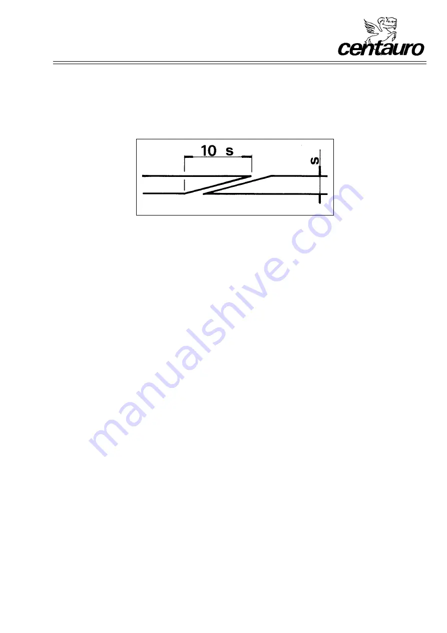
Fig. 15-4
Cut for brazing
5) Rational welding, well flattened and straight
The welding may be done in two ways: with the brazing system by overlapping, or by electric melting by means of
automatic machines.
In the first case (brazing), the ends of the blade are cut square and bevelled so that they can overlap for a section
of ten times the thickness of the blade (fig. 15-4).
The ends prepared in this way are then locked on the welding appliance, taking care of their alignment, and a plate
of special alloy is placed between the surfaces of the bevel that have to be spread with de-oxidant (borax, which
should be diluted with clean water so as to create a mush).
If the heating for welding is done electrically, it must be done slowly so as to reach incandescence; if it is done with
pressed irons, they need to have a temperature of approximately 900°C (light red).
Cooling must also be done slowly so that a very fragile hardening structure is not formed in the steel. In the event
of cooling coming about quickly (electric equipment for brazing), it is necessary to temper the part affected by taking
it up to a dark red colour for over twenty seconds. If the welding is done by electric melting, it is necessary to take
special care over the tempering operation. Having made the joint, it is necessary to flatten and level the blade so
that the thickness is as equal as possible to the rest of the blade. It is likewise necessary to check by means of
a check-rule that the welding is perfectly flat and straight to prevent dangerous oscillation of the blade during
operation.
16.
MAINTENANCE
16.1.
Machine maintenance
16.1.1.
Belt replacement
This is only possible after removing the bottom flywheel. Therefore, unloose the screws locking the motor and the belt
tightener screw; afterwards unloose the two non-marked screws registering the flywheel at the rear of the machine and
remove the head screw and relative washer that hold the bottom shaft in its seat. Then take out the flywheel with the
relative shaft and replace the belts; reassemble it all taking care not to move the marked screws registering the shaft
so as not to alter the alignment of the flywheel.
The belts have the type identifying their dimensions marked; if this marking is illegible, they can be requested, through
our area dealer, specifying:
•
machine model (with flywheel diameter)
•
year of manufacture
•
motor power and r.p.m.
•
motor pulley diameter
16.1.2.
Flywheel rubber covering replacement
Remember that this must be done when the covering appears worn or damaged (for example as a consequence of
accidental breakage of the blade). It is necessary to call our area dealer.
Summary of Contents for SP 400
Page 29: ...B 29 Tab 1 SP 400 ...
Page 31: ...B 31 Tab 2 SP 500 SP 600 SP 700 800 SP ...
Page 33: ...B 33 Tab 3 SP 500 SP 600 ...
Page 35: ...B 35 Tab 4 SP 700 ...
Page 37: ...B 37 Tab 5 SP 800 ...
Page 39: ...B 39 Tab 6 SP 500 SP 600 SP 700 ...
Page 41: ...B 41 Tab 7 SP 800 ...
Page 43: ...B 43 Tab 8 SP 500 SP 600 ...
Page 45: ...B 45 Tab 9 SP 700 SP 800 ...
Page 47: ...B 47 Tab 10 SP 500 SP 600 SP 700 SP 800 ...