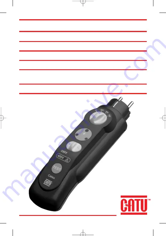
CATU CATEX DT-150 Accessory Installation Manual Download Page 1

1

CATEX

TM

DT-150

CONTRÔLEUR D’INSTALLATIONS ELECTRIQUES

ELECTRICAL INSTALLATIONS TESTER

PRÜFGERÄT FÜR ELEKTROINSTALLATIONEN

CONTROLADOR DE INSTALACIONES ELECTRICAS

C O N T R O L E T O E S T E L   V O O R   E L E K T R I S C H E
INSTALLATIES

CONTROLADOR DE INSTALAÇÕES ELÉCTRICAS

g

Summary of Contents for CATEX DT-150

Page 1: ...LATIONS ELECTRIQUES ELECTRICAL INSTALLATIONS TESTER PRÜFGERÄT FÜR ELEKTROINSTALLATIONEN CONTROLADOR DE INSTALACIONES ELECTRICAS C O N T R O L E T O E S T E L V O O R E L E K T R I S C H E INSTALLATIES CONTROLADOR DE INSTALAÇÕES ELÉCTRICAS ...

Page 2: ...2 ...

Page 3: ...ncia de tensión 230 V Diodo rojo de presencia de tensión 400 V CATEX DT 150 PRÜFGERÄT FÜR ELEKTROINSTALLATIONEN Anschlußstecker Bereichsschalter für Fehlerspan nungsauslösung Grüne LED für die Erdung Rote LED für die Phasenortung Umschalter für die Phasenortung Testknopf Rote LED für das Anliegen einer Spannung von 230 V Rote LED für das Anliegen einer Spannung von 400 V NEDERLANDS CATEX DT 15O CO...

Page 4: ...on CONTRÔLE DE RACCORDEMENT A LA TERRE Sur la face avant symbolisant une prise de courant 2 P T allumage de la diode verte continuité du conducteur de protection à la terre Attention si vous constatez l allumage uniquement de la diode verte situation anormale voir Situations particulières n 3 CONTRÔLE DE LOCALISATION DE PHASE Une prise de courant est habituellement câblée avec la phase à droite le...

Page 5: ... par le CATEX DT 150 sont les shémas TT et TN Concernant le schéma IT se conformer à la partie 6 de l annexe à la norme NF C 15 100 1991 SPÉCIFICATIONS TECHNIQUES ACCESSOIRES Votre contrôleur d installations électriques CATEX DT 150 a été conçu suivant les normes CEI 1010 1 et NF EN 61010 1 Tension d utilisation 230 V 10 Fréquence 50 60 Hz 10 Température d utilisation 15 C 45 C Température de stoc...

Page 6: ...nstallation triphasée 230 volts seul le voyant 230 volts est allumé 3 Le circuit est sous 230 volts câblage entre phases issues d une installation diphasée 230 volts seul le voyant 230 volts est allumé 4 La terre n est pas raccordée Séparez votre installation de toute source de tension vérifiez la nature du réseau mis en oeuvre ainsi que le câblage du circuit Avant toute intervention appliquez les...

Page 7: ...ng a 2P G power outlet lighting of green diode continuity of ground protection conductor Caution if the green diode lights up on its own the situation is abnormal See special situations No 3 PHASE LOCALIZING TEST Normally a power outlet is cabled with the phase on the right the neutral on the left and the ground pin uppermost If this condition is complied with Set switch to the right red LED ident...

Page 8: ...onform with part 6 of the appendix to standard NFC 15 100 1991 TECHNICAL SPECIFICATIONS AND ACCESSORIES Your CATEX DT 150 electrical installation tester has been designed to standards IEC 1010 1 and NF EN 61010 1 Load voltage 230 V 10 Frequency 50 60 Hz 10 Operating temperature range 15 C 45 C Storage temperature range 25 C 70 C Installation category II Protection degree IP 40 IK03 Pollution degre...

Page 9: ...ns tallation 3 The circuit is at 230 volts and cabling between phases from a two phase 230 volt ins tallation 4 Ground is not connected Separate your installation from any source of voltage check the nature of the network implemented and the cabling of the circuit Before action apply the safety regulations prescribed by UTE C 18 510 CASE No 3 Caution if you identify only the protection conductor c...

Page 10: ... CONTROL DE CONEXIÓN A TIERRA En la cara frontal simbolizando una toma de corriente 2P T encendido del diodo verde continuidad del conductor de protección de tierra Atención Si sólo se enciende el diodo verde situación anormal ver Situaciones particu lares nº 3 CONTROL DE LOCALIZACIÓN DE FASE Una toma de corriente se cablea habitualmente con la fase a la derecha el neutro a la izquierda y la espig...

Page 11: ...neutro tenidos en cuenta por el CATEX DT 150 son los esquemas TT y TN Por lo que se refiere al esquema IT remitirse a la parte 6 del anexo de la norma NF C 15 100 1991 ESPECIFICACIONES TÉCNICAS Y ACCESORIOS El controlador de instalaciones eléctricas CATEX DT 150 ha sido diseñado según las normas CEI 1010 1 y NF EN 61010 1 Tensión de utilización 230 V 10 Frecuencia 50 60 Hz 10 Temperatura de utiliz...

Page 12: ...tios sólo está encendido el piloto 230 voltios 3 El circuito está bajo 230 voltios cableado entre fases procedente de una instalación bifá sica 230 voltios sólo está encendido el piloto 230 voltios 4 La tierra no está conectada Aleje la instalación de toda fuente de tensión y verifique la naturaleza de la red utilizada así como el cableado del circuito Antes de cualquier intervención aplique las r...

Page 13: ... DER ERDUNG Auf der Vorderseite in der symbolischen Darstellung einer Steckdose die grüne LED leuchtet die Erdung des Schutzleiters ist durchgängig Achtung Sollte nur die grüne LED aufleuchten so liegt eine abnorme Lage vor Siehe unter Sonderfälle Nr 3 KONTROLLE DER PHASENLAGE Eine Steckdose ist gewöhnlich so angeschlossen daß die Phase rechts der Nulleiter links und der Erdanschluß oben zu liegen...

Page 14: ...n 230 V zwischen Phase und Null Anwendung finden Die von den Geräten CATEX DT 150 berücksichtigten Nulleiterbedingungen sind die Schaltungen EE und EN Hinsichtlich der Schaltung IT siehe Teil 6 der Anlage zur Norm NF C 15 100 1991 Technische Daten Zubehör Das Prüfgerät für Elektroinstallationen CATEX DT 150 ist den Normen IEC 1010 1 und NF EN 61010 1 gemäß entwickelt worden Arbeitsspannung 230 V 1...

Page 15: ...kreis liegen 230 V an Der Anschluß der beiden Phasen stammt aus einer zwei phasigen Anlage mit einer Spannung von 230 V Es leuchtet nur die LED 230 V 4 Die Erde ist nicht angeschlossen Trennen Sie die Anlage von jeder Spannungsquelle ab und überprüfen Sie die Art des angeschlossenen Netzes und die Verkabelung des Kreises Vor jedem Eingriff sind die Sicherheitsvorschriften gem UTE C 18 510 in Anwen...

Page 16: ...CONTROLE AANSLUITING OP DE AARDE Op de voorkant is een stopcontact 2P A symbolisch voorgesteld de groene LED gaat branden continuïteit van de beschermingsgeleider met de aarde Opgelet indien alleen de groene LED oplicht abnormale toestand vo apparoat is defekt CONTROLE VAN DE LOKALISERING VAN DE FASE Een stopcontact is gewoonlijk bedraad met de fase rechts de nulleider links en het aard contact na...

Page 17: ... 2P A 1O 16 A van de eenfasige elektrische circuits 23O volt tussen fase en nulleider De belastingstoestanden van de nulleider waarmee door de CATEX DT 15O rekening gehouden wordt zijn de schema s TT en TN Wat het schema IT betreft zich naar het gedeelte 6 van de bijlage bij de norm NF C 15 1OO 1991 schikken TECHNISCHE SPECIFICATIES TOEBEHOREN Uw controleschakelaar van elektrische installaties CAT...

Page 18: ...en 4OO volt branden 2 Het circuit staat onder 23O volt bedrading tussen fasen afkomstig van een driefase ninstallatie 23O volt alleen het controlelichtje 23O volt brandt 3 Het circuit staat onder 23O volt bedrading tussen fasen afkomstig van een tweefase ninstallatie 23O volt alleen het controlelichtje 23O volt brandt 4 De aarde is niet aangesloten Scheid uw installatie van elke spanningsbron af c...

Page 19: ...erde continuidade do condutor de protecção à terra Cuidado se constate que apenas a ignição do diodo verde trata se de uma situação anormal o seu aparelho apresenta um defeito CONTROLO DE LOCALIZAÇÃO DA FASE Uma tomada de corrente é habitualmente sob cabos com a fase à direita o neutra à esquerda e o espeto de terra orientado para cima se esta condição for respeitada Colocar o inversor à direita o...

Page 20: ...ricas CATEX TM DT 150 foi concebido em conformidade com as normas CEI 1010 1 e NF EN 61010 1 Tensão de utilização 230 V 10 Frequência 50 60 Hz 10 Temperatura de utilização 15 C 45 C Temperatura de armazenagem 25 C 70 C Categoria de instalação Grau de protecção IP 40 IK03 Duplo isolamento Grau de poluição 2 Utilização apenas em condições secas hr 50 alt 2000m Utilização em instalações de categorias...

Page 21: ...volts está aceso 3 O circuito encontra se sob 230 volts de cabos entre fases oriundas de uma instalação difásica 230 volts apenas o indicador luminoso 230 volts está aceso 4 A terra não está ligada Separar a sua instalação de qualquer fonte de tensão verificar a natureza da rede instalada assim como os cabos do circuito Antes qualquer invenção aplicar as regras de segurança prescritas pelo UTE C 1...

Page 22: ...22 1 M88 790 N Ph ...

Page 23: ...23 ...

Page 24: ...24 CATU S A 10 A 20 AVENUE JEAN JAURÈS 92222 BAGNEUX CEDEX FRANCE TÉLÉPHONE 01 42 31 46 00 TÉLEX 634 999 F TÉLÉCOPIE 01 42 31 46 32 99 3542 mai 2001 Primafolio ...

Reviews: