background image

Protocol Analyzer Projects

Catalyst Enterprises, Inc.

9

Protocol Analyzer Projects

Protocol Analysis is performed by defining and running a Protocol Analysis Project, 
which defines what will be captured, what the analyzer will trigger on and capture 
memory settings. Defined projects may be saved as project *.wac files for later use.

Quick Start

To get a comprehensive overview of your analyzer’s capabilities:

1. Install the Analyzer software. See "Software Installation" on page 4.

2. Set up your Analyzer. See "Hardware Setup" on page 4. 

3. Launch your Analyzer software. See "Launching Your Analyzer" on page 7 for 

launching instructions.

4. On the Analyzer Menu Bar click 

File, New 

to open a Protocol Analyzer dialog

.

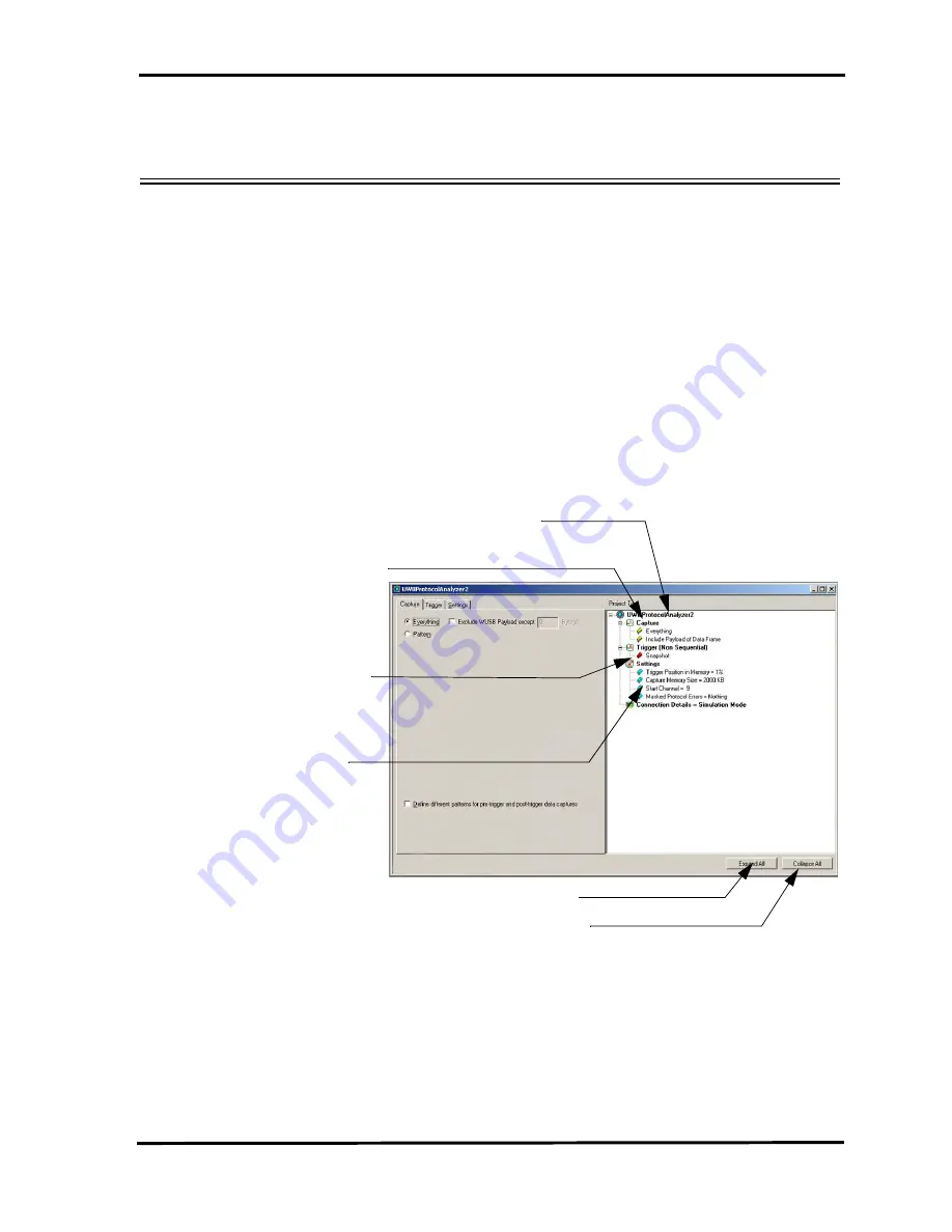
Figure 3. New Protocol Analyzer Project Dialog

The New Project dialog opens with default settings to capture 

Everything

 on the bus 

and to 

Trigger On 

on 

Snapshot. 

(Meaning that the analyzer captures everything 

immediately without triggering on anything in particular).

Project tree display 

What will be captured

What will analyzer trigger on

Capture memory settings

Collapse All button hides details in Project tree

Expand All button expands collapsed Project tree


Summary of Contents for AirCom UWB Analyzer

Page 1: ...March 2007 P N 400 0103 001 User s Manual Version 1 22 ...

Page 2: ...RANTY OF ANY KIND EXPRESS OR IMPLIED USERS ARE FULLY RESPONSIBLE FOR THEIR APPLICATION OF ANY PRODUCTS THE SOFTWARE LICENSE AND LIMITED WARRANTY FOR THE ACCOMPANYING PRODUCT ARE SET FORTH IN INFORMATION THAT SHIPPED WITH THE PRODUCT AND ARE INCORPORATED HEREIN BY THIS REFERENCE IF YOU ARE UNABLE TO LOCATE THE SOFTWARE LICENSE OR LIMITED WARRANTY CONTACT LECROY CORPORATION FOR A COPY Copyright Copy...

Page 3: ... An acknowledgement of reception must continue to be received by the UWB intentional radiator at least every 10 seconds or the UWB device must cease transmitting This equipment may only be operated indoors Operation outdoors is in violation of 47 U S C 301 and could subject the operator to serious legal penalties Note This device must be installed in a location that is not accessible to the genera...

Page 4: ...Catalyst Enterprises Inc Copyright iv ...

Page 5: ...cting via Ethernet 5 Connecting to a Network 5 Connecting via Hub Switch or Similar device 6 Launching Your Analyzer 7 Analyzer 7 Software Launched 8 Operating in Simulation Mode 8 Protocol Analyzer Projects 9 Quick Start 9 Example Projects 12 Run an Example Protocol Analyzer Project 13 Saving a Trace Capture 14 Protocol Analyzer Project Setup 15 Data Capture Setup 16 Capture Everything 16 Pre and...

Page 6: ...28 Analyzer Settings 29 Add a Project Note 29 Pre Trigger 30 Frame Generator Projects 31 Frame Generator Setup 31 Data Display Manipulation 32 View Packets Display 32 Spec View 33 Spec View Options 34 Data View 35 Search for Data Pattern 35 Viewer Toolbar 37 Layers Toolbar 39 Collapsing Layers 39 Interpretation Aids 40 Set Direction Alias 41 User Defined Decoding UDD 42 Faded Packets 45 ...

Page 7: ...ort Toolbar 53 Export as Microsoft Excel file 53 Save as Text 53 Print Statistical Report 53 Print Preview 54 Report Display Settings 55 Link With Sample View 56 Formatting the Statistical Report View 57 Filtering Column Content 57 Hiding Columns 58 Sorting Column Content 58 Filtering Toolbar 59 Advanced Filter 60 Filter Setup 60 Using Pointers and Bookmarks 61 Pointers 61 Bookmarks 62 Search 64 D...

Page 8: ...ucture 86 Protocol Extraction Section 87 Product Section 87 Protocol Decoding Section 87 Define Option Block 87 Valid Range Block 88 ASL Statements 89 Addfield 89 GetData 90 If 91 Repeat Count 92 SetFieldTableHeader 94 Functions 96 LengthOf Data 96 StartOf FIELDIdentifier 96 ValueOf Identifier 96 CURPOS 97 EOD 97 China Restriction of Hazardous Substances Table 98 Index 99 ...

Page 9: ...tions are included Analyzer Overview The Catalyst AirCom UWB Analyzer is capable of capturing and analyzing UWB traffic The analyzer supports the following Capture and Trigger of UWB events such as transactions and packets Pre and Post Trigger pattern capture Real time Protocol Error detection Integrated Frame Generator to send user defined UWB frames over the air Comprehensive Statistical Report ...

Page 10: ...ternal trigger Output LEDs Each link is supported by 4 LEDs with the following functionality Green This LED is illuminated indicating an active link Yellow This LED is illuminated when there is traffic on a link Red This LED illuminates when an error occurs Blue This LED is illuminated when a trigger occurs ...

Page 11: ...irCom UWB Analyzer Carrying Case SMB to BNC External Trigger Cables 24 Unpacking Your Analyzer Inspect the received shipping container for any damage Unpack the container and account for each of the system components listed on the accompanying packing list Visually inspect each component for absence of damage In the event of damage notify the shipper and Catalyst Enterprises Retain all shipping ma...

Page 12: ...will automatically start unless the Auto Run is turned off In this case select the CD ROM from My Computer and double click autorun exe 3 From the CD ROM autorun application choose the Install Software menu item and then choose UWB AirCom Software System restart You must restart your computer before you can use your Analyzer software Error Message If you get an error message during installation of...

Page 13: ...e IP address to the Analyzer until the Analyzer software is started When the user starts the software the user may be prompted if they wish the software to automatically use the offered IP address or if they wish to assign a specific IP address the assigned IP address needs to be on the same network segment as the host computer The menu also allows the user to save the selected option automatic or...

Page 14: ...the software to automatically use the offered IP address or if they wish to assign a specific IP address the assigned IP address needs to be on the same network segment as the host computer The menu also allows the user to save the selected option automatic or specific address If the assigned IP address is not available the OS will notify the user of an IP address conflict After the user clicks OK...

Page 15: ...a list of available devices Choose the device to be connected to and click OK to launch the software If no devices are available you may choose to run in simulation mode To run in simulation mode check the Hardware Not Installed Simulation Mode option button and click OK The next time you run the software it will connect to the last used device if it is still available To launch the Analyzer softw...

Page 16: ...ol bar but with the limitation that the Analyzer will operate only on static previously captured bus data Limitations The Simulation mode lets you try all of the available functions but keep in mind that the system is not capturing any real data and is displaying only pre captured results Open Open Sample File Save Open Last Saved Analyzer Project Run Project Stop Project Cancel Project Scan UWB C...

Page 17: ...up your Analyzer See Hardware Setup on page 4 3 Launch your Analyzer software See Launching Your Analyzer on page 7 for launching instructions 4 On the Analyzer Menu Bar click File New to open a Protocol Analyzer dialog Figure 3 New Protocol Analyzer Project Dialog The New Project dialog opens with default settings to capture Everything on the bus and to Trigger On on Snapshot Meaning that the ana...

Page 18: ...on Figure 4 Typical Packet View Results Display The results display shows each transaction for every layer identified in a different color and the data direction identified with data direction arrows Upstream traffic is identified with the arrow from right to left This arrow direction indicates upstream traffic Downstream traffic is identified with the arrow left to right This arrow direction indi...

Page 19: ...configuring the viewer display The Protocol Analyzer Project dialog offers you a comprehensive set of choices to create a trigger and capture project satisfying some specific need You may set the Analyzer to Capture specific patterns See Data Capture Setup on page 16 Capture different patterns pre and post trigger Exclude parameters from capture Trigger on a Pattern or sequence of patterns See Tri...

Page 20: ...e comes with a pre defined folder Directory structure for storing all files All pre defined example files are stored in the following Folder c Program Files Catalyst AirCom Examples It is strongly recommended that you open some of these files to get an introduction to the types of projects that can be created for the Analyzer Project file type definition wac Protocol Analyzer file was Sample file ...

Page 21: ...Protocol Analyzer Projects by looking in c Program Files Catalyst AirCom Examples 3 Choose an example wac file and click Open to display the example project dialog Figure 5 Sample Protocol Analysis Project 4 Click the Run Project button to execute the pre defined example 5 Once the project runs you will see an analyzer trace capture display similar to the one shown in Figure 6 ...

Page 22: ...rojects 14 Figure 6 Analyzer Trace Capture Display See Data Display Manipulation on page 32 and Display Configuration on page 66 for details about the results display Saving a Trace Capture You may save a Trace Capture for review at a later time ...

Page 23: ...ettings for the last project run Default Project Clicking File New opens a new project with default settings that you can modify as required Last Project Clicking the Green button opens the last project saved You may modify this project as required New Project To start a New project click File on the main menu bar and choose New Figure 7 New Trigger and Capture Project Dialog ...

Page 24: ...tings will immediately start a data capture to give the user a quick view of bus activity Figure 8 Capture Everything Default You may elect to exclude the Payload from the capture by checking Exclude Payload except and if desired specify the number of bytes of the payload to be included The data capture may be refined by choosing Pattern and then selecting a specific pattern s for capture Addition...

Page 25: ...in the parameter window and click the Add button This will open selection dialogs for each of the categories displaying all of the parameters for that category All of the patterns added will appear in the project tree Exclude patterns Check this box to allow for the capture of everything except the patterns that have been added to the Project Tree When this box is checked the Primitive category is...

Page 26: ...y define one set of patterns for capture prior to the occurrence of a trigger and another set of patterns for capture after the occurrence of a trigger The selections and setup procedure is the same for both the Pre Trigger capture and the Post Trigger capture Check Define different patterns for pre trigger and post trigger data capture to enable the Post Trigger Capture tab Figure 11 Post trigger...

Page 27: ...12 Frame Common Fields Setting 1 Enter values in the Common Fields area for Source ID Destination ID Sequence Control and Stream Index 2 Click the down arrow next to the Secure drop down combo box and choose Any Plain Text or Secure 3 Click the down arrow next to the Burst Mode drop down combo box and choose Any Normal or Burst 4 Click the down arrow next to the Type drop down combo box and choose...

Page 28: ...mmand and Data specific fields offer additional options WUSB Packet Double click WUSB packet to display the WUSB packet specification dialog 1 Enter values in the Common Fields area for Source ID Destination ID Sequence Control and Stream Index 2 Choose the Specific Fields similarly to the way described for Frames ...

Page 29: ...estination ID Sequence Control and Stream Index 2 Click the down arrow next to the Information Element drop down combo box and choose an Information Element Type for capture WUSB Data Pattern Double click WUSB Data Pattern to display the WUSB Data Pattern specification dialog 1 Enter values in the Common Fields area for Source ID Destination ID Sequence Control and Stream Index 2 Enter values for ...

Page 30: ...alyst Enterprises Inc Protocol Analyzer Projects 22 Protocol Errors Double click Protocol Errors to display the Protocol Errors selection dialog Check the desired Protocol Error s for capture and click OK ...

Page 31: ...captured data stream The following are three ways to trigger the analyzer with Pattern selected Trigger on any added pattern Any Trigger Mode Trigger on timer External Trigger Trigger on a sequence of patterns Sequential Trigger Mode Snapshot Mode To trigger immediately on any pattern check the Don t care Snapshot button Figure 14 Default Trigger Selected Manual Trigger Mode In the Manual Trigger ...

Page 32: ...patterns for triggering check the Pattern button in the Trigger On dialog Figure 15 Select Patterns for Trigger The Parameters window displays the following trigger pattern choice categories Choose a parameter Either highlight the category and click the Add button or double click the category to open a corresponding definition dialog To remove an item from trigger highlight it in the Project tree ...

Page 33: ...after a set time To set the timer value double click Timer in the Patterns window of the Capture Project dialog to open the Timer dialog Check the Time unit desired enter the Timer Value and click OK External Trigger You may trigger on an external trigger To set up the trigger click the External Trigger category Click a desired triggering condition option button and click OK ...

Page 34: ...or inserting a timer in the triggering sequence to delay detection of the next pattern in the sequence To insert a timer in the trigger list Double click Timer to open the timer definition dialog Enter the desired Time Value choose the Time Unit and click OK Defining Patterns The definition of patterns for the sequential trigger mode is identical to the Pattern mode with the following exception In...

Page 35: ...sequentially in the order that they were entered under the Trigger On category When the project is run the analyzer will detect the occurrence of each pattern in order and trigger on the last one The sequence of triggering patterns can be re ordered if desired To change the sequence order highlight a trigger pattern and use the enabled green Up or Down arrow to move it to a new position ...

Page 36: ...50 in the Manual trigger and Pattern mode You may change this percentage by dragging the slider to the desired value The capture of the specified percentage of the data prior to the triggering event cannot be guaranteed and may in some cases be 0 This can occur in cases where the triggering event occurs before the required number of pre trigger event data can be stored In these cases the data disp...

Page 37: ... active channel to be analyzed Protocol Error Mask Click the Protocol Error Mask button to open the Protocol Error Mask dialog Check the Protocol Errors that you wish to not display in the sample view Add a Project Note To enter and save information about the current project click the Note button and enter the data about the project Figure 19 Project Note To run the project click the run button ...

Page 38: ...ter the triggering event The operation of the pre trigger in the data memory is conceptually illustrated in Figure 20 Pre trigger Data is the capture of the specified percentage of the data prior to the triggering event cannot be guaranteed and may in some cases be 0 This can occur in cases where the triggering event occurs before the required number pre trigger event data can be stored In these c...

Page 39: ...instructions how to create a Frame Generator file see Appendix A on page 69 Note To create a new Frame Generator project click the New button and select Frame Generator Figure 21 Initiator Dialog Frame Generator Setup 1 Check the Run Frame Generator check box and then click the ellipses button next to the Frame File Name list box and choose a Frame Generator wpg file 2 Choose Transmission mode by ...

Page 40: ...re available for quick access to data viewer display features Figure 22 View Packets Display Enabling Toolbars To customize your Sample Viewer Display workspace you can enable disable and reposition the available toolbars To display or hide toolbars click View Toolbar and check or uncheck the desired toolbar Once enabled the toolbars can be docked to the viewer display window or allowed to float o...

Page 41: ...ick View on the main toolbar and choose Show Spec View You may also get a Frame specification by right clicking on any frame in the sample viewer Note If you scroll the sample viewer display with an open Spec View the contents of the Spec View will change to those for whichever Frame is the first item in the viewer display Figure 23 Spec View of Frame First item in viewer is a Frame ...

Page 42: ... Spec View Options To change the Spec View options right click in the Spec View window and choose the data radix Hexadecimal or Binary choose to show data only or copy Field Contents or all Contents to save in a different format Figure 24 Spec View Format ...

Page 43: ...e 25 Complete Payload Data Display Search for Data Pattern To search for specific data patterns right click the Frame Data Field and choose Open as Data View Enter a Pattern to search for and click Find Repeat to find the next instance of the data pattern Figure 26 Search for Data Pattern You may configure the data display to Show Hide the ASCII Pane Default is Show specify the number of bytes per...

Page 44: ...ay Manipulation 36 To save the data in a special file click the Export button to open a Save As dialog Choose a folder where to save the file a file name and Save As type Either Text or Binary and click OK Figure 27 Data Exported as Text ...

Page 45: ...e Full Screen button to increase the data display area to full on the screen Click the Zoom In button to magnify the data display area of interest on the screen In column and frame text view it increases the column width only Click the Zoom Out button to scale the data display area to display more data lines on the screen In column and frame text view it decreases the column width only ...

Page 46: ... Click the Wrap Packets button to wrap the packet data in the display to eliminate the need for horizontal scrolling Expand Collapse all Layers button expands or collapses layers to simplify the results display Click the down arrow to expand or collapse specific layers GOTO button locates cursors in the results display Click the down arrow to select cursor to go to ...

Page 47: ...ayer and choose Expand All Performing this on a lower layer will configure the display to show only that layer and the one s above Click the Show Hide Transfer button on the Layers Toolbar to toggle between show and hide of the Transfer layer Click the Show Hide Transaction button on the Layers Toolbar to toggle between show and hide of the Transaction layer Click the Show Hide WUSB Packet button ...

Page 48: ...he corresponding field title and choosing Hide Field To restore a field to the display right click on in any field and choose the hidden field to be restored Note Only the fields previously hidden will appear in the restore list Byte Order For reviewing enhancement you may change the byte order in fields marked by an arrow Right click in the field Select Byte Order and choose the ordering Big Endi...

Page 49: ... allows you to assign a meaningful name to each traffic direction to assist in interpreting the Sample View 1 To assign direction names in an open Sample View click Configuration on the Menu Bar and choose Set Direction Alias 2 Assign a meaningful name to each traffic direction and click OK 3 The assigned direction alias will apply to all sample files that are opened after it has been set Directio...

Page 50: ...sly defined script click View on the main toolbar and choose UDD Assignment to display the UDD Assignment dialog Figure 28 UDD Assignment Dialog To make the pre defined scripts available for assignment click the ADD button and locate the scripts in Application Directory System Script folder Choose the required script and click Open Repeat for additional files as required To assign a script to an e...

Page 51: ...ign Script Choose an endpoint stage assignment from the Command dropdown list and click OK Figure 30 Script Assigned Click OK to complete assignment A Show Decoding icon will appear in the Sample View for the endpoints with the script assignment Assign Protocol Button ...

Page 52: ...Catalyst Enterprises Inc Data Display Manipulation 44 Click the Show Decoding Icon to display the decoding table for that endpoint Figure 31 Decoding Table Show Decoding Icon ...

Page 53: ...same as its related TG packet 3 WUSB In Out and Handshake Packets If these packets are shown beneath their related Transfer then they are shown as non faded otherwise they are shown as faded 4 WUSB DN Packets If these packets are shown beneath a Transfer then they are shown as faded 5 Frames Frame fading is the same as its related WUSB Packet MMC DN or In Out Handshake In the following snapshot th...

Page 54: ...Catalyst Enterprises Inc Faded Packets 46 Figure 32 Illustration of Faded Packets ...

Page 55: ...lick the option button next to the From cursor selection drop down list Then click the From down arrow and choose the 1st cursor click the To down arrow to choose the 2nd cursor and click OK The resulting report is limited to the capture between the cursors Report Between Events Click the option button next to the From the event selection dropdown list Then click the From down arrow to choose the ...

Page 56: ...r options to display only items of interest These report categories incorporate drop down list boxes offering pre defined and custom options For details see Formatting the Statistical Report View on page 57 Frame Report To display the Frame report view click the Frame Tab The Frame report displays the report data in columns with the following information Frame WUSB Packet Transaction Group Transfe...

Page 57: ... with the following information Transaction Group Report To display the Transaction Group Report click the Transaction Group tab The Transaction Group report displays the report data in columns with the following information Type Host Address Device Address End Point Acknowledge Channel Length Duration Count Occurrence Percent Host Address Channel Number of Frames Count Occurrence Percent ...

Page 58: ...port displays the report data in columns with the following information IE Report To display the IE Report click the IE tab The STP Transport report displays the report data in columns with the following information Type Host address Device Address Count Occurrence Percent Protocol Type Host Address Channel Count Occurrence Percent ...

Page 59: ...lays the report data in columns with the following information Performance Report To display the Performance Report click the Performance tab The Performance report displays the report data in columns with the following information Packet PE ID Channel Count Occurrence Percent Host Address Device address End Point Throughput Bus Utilization Efficiency Count Occurrence Percent ...

Page 60: ...stical Report 52 Other Report To display the Other Report click the Other tab The Other report displays the report data in columns with the following information Sample Time Total Idle Time Total Traffic Time Average Bytes Per Frame ...

Page 61: ...e Excel file in and an appropriate file name and click Save Save as Text Choose a folder to save the Text file in and an appropriate file name and click Save Print Statistical Report Click the Export to Excel Button on the Statistical Report Toolbar to open the Export to Excel dialog Click the Save as Text Button on the Statistical Report Toolbar to open the Export to Text dialog Click the Print B...

Page 62: ...t Enterprises Inc Statistical Report 54 Print Preview Figure 34 Sample Print Preview of Report Click the Print Preview Button on the Statistical Report Toolbar to display a preview of the report to be printed ...

Page 63: ... particular analysis need You may globally choose the columns for display thereby eliminating the need to show hide columns individually Use the Setting dialog to configure the display for each page Figure 35 Statistical Report Column Setting Click the Setting Button on the Statistical Report Toolbar to open the Setting dialog ...

Page 64: ...mple viewer Click the Jump to Previous Button on the Statistical Report Toolbar to go to the previous instance of the selected type in the Sample Viewer Click the Jump to Next Button on the Statistical Report Toolbar to go to the next instance of the selected type in the Sample Viewer Click the Jump to Specific Button on the Statistical Report Toolbar to go to the instance specified as N of M item...

Page 65: ...by column Filtering Columns by item Hiding any column on the display Filtering Column Content To filter column content click the down arrow in the heading for that column and choose the items that you wish to be displayed The default is All By checking a specific item you exclude everything but that item for display Choosing Custom allows you to specify more than one item for display Check the ite...

Page 66: ...he column and choose Hide To unhide a column right click on any column and choose Unhide Sorting Column Content To sort column content click the heading for that column Repeated clicking of the column heading will sort the column in ascending or descending order Figure 36 Toggling Type Sort Order ...

Page 67: ... Filter selection button Advanced Filter button opens the Advanced Filter specification dialog Hide Device button hides packets associated with specific hardware Click the down arrow on the button to select hardware Hide Transaction Group Packets with no WUSB Data Packets button Hide Naked Packets button Hide no Handshake WUSB Packets button ...

Page 68: ...er Setup Dialog 1 Choose the packets that you wish to filter in the Filter Item area 2 Define the filtering domain by choosing options for Secure Packets Rate Src Address Dest Address and Stream Index 3 Items selected for filtering may be designated as Show or Hide by selecting the corresponding option for Filter Type Click the Filter Enable button to enable the filter To display the Filter setup ...

Page 69: ...inter within the viewer data display click the right mouse button in the gray bar on the left side of the sample viewer next to the line where you wish to see the pointer Note You may also left click to set the X pointer and right click to set the Y pointer in the frame and the column view by clicking in the narrow strip on the very left side of a cell Time differences between the pointers are dis...

Page 70: ...t you can rapidly return to that point To create a bookmark 1 Right click in the sample viewer on a packet where you wish to place the bookmark 2 Choose Bookmark from the shortcut menu to open the Bookmark dialog 3 Choose a name for the bookmark enter a description for the bookmark and click the Add button Repeat for additional bookmarks Bookmark ...

Page 71: ...st Enterprises Inc 63 Finding a Bookmark To find a bookmark right click the mouse in the sample viewer and click bookmark Figure 39 Go To Bookmark Dialog Box Highlight the bookmark that you wish to go to and click the Go button ...

Page 72: ...ies when selected offers additional choices to refine the search Check the desired items for the selected category Search Direction The default setting is Forward With this setting clicking Find Next will locate the specified search item from the current position forward Check Backward to search backward from the current position Search From Choose a starting to begin or continue a search Start of...

Page 73: ... you redefine the data capture search parameters Data Pattern Search for Data Pattern allows you to search for A specific Data Pattern Data Payload Length Data Pattern and Data Payload Length Figure 41 Search for Data Pattern Search Domain Define the search domain by choosing options for Secure Packets Rate Src Address Dest Address and Stream Index ...

Page 74: ...field Check uncheck Visible Viewer Settings Change fonts Wrap packets Enable Disable tool tip Fit Text to cells Time Stamp Origin Save Display Configurations in a file Load Display Configuration settings from a file To configure the display for your preferences click Configuration on the main toolbar and choose Viewer Configuration Figure 42 View Packets Viewer Configuration Dialog Field Settings ...

Page 75: ...unt text box Choose Time Stamp Origin by checking Absolute Trigger Current Position or System time option button Color To change the background or text color in a packet field header or data select it from the packet field tree and click the desired button Choose an appropriate color and click OK Display Fonts To change display fonts click the Font button to open the Font dialog box Choose the des...

Page 76: ...Catalyst Enterprises Inc Display Configuration 68 ...

Page 77: ...a File Size Each file is limited to a maximum of 128K 4 byte wide lines Commenting You may add comments to each line which must be preceded by double slashes as shown in the following example 01 00 00 00 01 00 00 00 01 00 00 00 01 00 00 00 Line 1 00 00 00 00 01 00 00 00 01 00 00 00 01 00 11 00 Line 2 00 00 00 00 01 00 00 00 01 00 00 00 01 00 00 00 Line 3 File Structure Each 32 bit line of a Patter...

Page 78: ...all other lines Bit25 Must set to one in the end line of Frames and to zero in all other lines Bit24 Must set to one in the start line of Frames and zero in all other lines Bytes 2 and 1 are not used and are reserved for future use Byte 0 is the Data Byte located as the right most byte on each line This byte contains either frame bytes for frame blocks or a delay value which is used to define dela...

Page 79: ...e 44 Frame Fields Definition As seen in the figure above a frame is a stream of structured formatted bytes defined in a specific order The user must insert the desired bytes values of the frame in the data byte portion of the Pattern file Byte 0 ...

Page 80: ...Start of MAC Header Octets 5 through 14 00 00 00 1C 00 00 00 00 00 00 00 01 00 00 00 EF 00 00 00 BE 00 00 00 00 00 00 00 00 00 00 00 00 00 00 00 C0 End of MAC Header 00 00 00 00 Start of MAC Payload Begins at Octet 15 00 00 00 00 00 00 00 00 00 00 00 00 00 00 00 24 00 00 00 00 00 00 00 00 00 00 00 00 00 00 00 00 00 00 00 00 00 00 00 00 00 00 00 00 00 00 00 00 00 00 00 00 00 00 00 00 00 00 00 FF 00...

Page 81: ... 00 00 00 00 00 80 00 00 00 06 00 00 00 00 00 00 00 01 00 00 00 00 00 00 00 00 00 00 00 40 00 00 00 00 00 00 00 00 00 00 00 FF 00 00 00 03 00 00 00 FF 00 00 00 11 00 00 00 11 00 00 00 11 00 00 00 11 00 00 00 11 00 00 00 11 00 00 00 11 00 00 00 11 End of MAC Payload 00 00 00 43 Start of FCS Octet Length 15 00 00 00 23 00 00 00 BA 02 00 00 05 End of FCS ...

Page 82: ...zer hardware to create delays between frames A delay block is a 32 bit time interval which counts with a 66MHz clock and can define an up to 65 second interval The following formula describes delay time Delay Value Delay time S 66000000 Fixed Delay There is a fixed delay between frames even if the user has not defined a delay value between frames It is about 2uSec for Single frames and 1 875uSec f...

Page 83: ...nserted in the data byte fields i e Byte 0 The following is an example that defines a delay block in a Pattern file For example 6us Delay Value 396 0x18C 20 00 00 8C 20 00 00 01 20 00 00 00 20 00 00 00 Example The following is an example file including an MMC packet and three DATA packets MMC 1 PHY header 01 00 00 00 00 00 00 38 00 00 00 00 04 00 00 90 00 00 00 00 MAC header 00 00 00 48 00 00 00 1...

Page 84: ... 00 00 00 00 00 00 00 00 00 00 00 00 00 00 00 00 00 00 WUSB App Code 00 00 00 00 00 00 00 01 MMC Code 00 00 00 01 Next MMC 00 00 00 FF 00 00 00 FF Reserved 00 00 00 00 00 00 00 00 WUSB channel Time 00 00 00 00 00 00 00 00 00 00 00 00 WCTA IE IE Length 00 00 00 1a IE Identifier WCTA_IE 00 00 00 80 W_DR_CTA 12 bytes EP Setup flag WCTA Type 00 00 00 70 ...

Page 85: ...is control status 00 00 00 A7 00 00 00 25 bvDINAck 00 00 00 0A 00 00 00 00 00 00 00 00 00 00 00 00 setup bytes 00 00 00 80 00 00 00 06 00 00 00 00 00 00 00 01 00 00 00 00 00 00 00 00 00 00 00 40 00 00 00 00 EOL EP Setup flag WCTA Type 00 00 00 00 Start time 00 00 00 FF 00 00 00 03 Device ID 00 00 00 FF MIC 00 00 00 11 00 00 00 11 00 00 00 11 ...

Page 86: ...00 E3 IN DATA 1 PHY header 01 00 00 00 00 00 00 1E 00 00 00 00 04 00 00 90 00 00 00 00 MAC header 00 00 00 C8 00 00 00 12 00 00 00 EF 00 00 00 BE 00 00 00 30 00 00 00 00 00 00 00 00 00 00 00 00 00 00 00 00 00 00 00 C0 Security 00 00 00 00 00 00 00 00 00 00 00 00 00 00 00 00 00 00 00 02 00 00 00 00 00 00 00 00 00 00 00 00 00 00 00 00 00 00 00 00 ...

Page 87: ...0 00 01 00 00 00 00 00 00 00 01 00 00 00 00 00 00 00 00 00 00 00 00 00 00 00 08 MIC 00 00 00 11 00 00 00 11 00 00 00 11 00 00 00 11 00 00 00 11 00 00 00 11 00 00 00 11 00 00 00 11 FCS 00 00 00 CE 00 00 00 FD 00 00 00 E6 02 00 00 83 IN DATA 2 PHY header 01 00 00 00 00 00 00 1E 00 00 00 00 04 00 00 90 00 00 00 00 MAC header 00 00 00 C8 00 00 00 12 00 00 00 EF ...

Page 88: ... 00 00 02 00 00 00 00 00 00 00 00 00 00 00 00 00 00 00 00 00 00 00 00 00 00 00 00 00 00 00 00 WUSB header 00 00 00 00 00 00 00 01 Low 4 bit is sequence number Data payload 00 00 00 FA 00 00 00 04 00 00 00 01 00 00 00 42 00 00 00 A2 00 00 00 00 00 00 00 00 00 00 00 00 MIC 00 00 00 11 00 00 00 11 00 00 00 11 00 00 00 11 00 00 00 11 00 00 00 11 00 00 00 11 00 00 00 11 FCS 00 00 00 B6 ...

Page 89: ... 00 C8 00 00 00 12 00 00 00 EF 00 00 00 BE 00 00 00 30 00 00 00 00 00 00 00 00 00 00 00 00 00 00 00 00 00 00 00 C0 Security 00 00 00 00 00 00 00 00 00 00 00 00 00 00 00 00 00 00 00 02 00 00 00 00 00 00 00 00 00 00 00 00 00 00 00 00 00 00 00 00 00 00 00 00 00 00 00 00 WUSB header 00 00 00 00 00 00 00 02 Low 4 bit is sequence number Data payload 00 00 00 00 00 00 00 01 MIC ...

Page 90: ...Catalyst Enterprises Inc Appendix A 82 00 00 00 11 00 00 00 11 00 00 00 11 00 00 00 11 00 00 00 11 00 00 00 11 00 00 00 11 00 00 00 11 FCS 00 00 00 B2 00 00 00 22 00 00 00 82 02 00 00 0E ...

Page 91: ...s or any structured data transferred over the USB bus or can be used to complement pre defined protocols This appendix is the essential reference for ASL users including definitions code snippets and complete examples The decode script files can be written in any text editor or using the Catalyst script editor and must be saved with an asl file extension Document conventions This appendix uses the...

Page 92: ...time Constant1 optional d x b Constant2 Optional Value Constant1 and constant2 are optional These can be any character string The value of the expressions is replaced by the corresponding strings in either decimal d hexadecimal x or binary b formats Examples This is a static string Field length is d LengthOf F1 Operators The following lists the operators accepted by ASL Operator precedence is that...

Page 93: ...bout functions see page 96 Examples Expression 1 0x2A and LengthOf F1 Expression 2 ValueOf F1 2 or not LengthOf F2 10 Expression 3 4 LengthOf F1 ValueOf F2 The priority of evaluation is as follows Not and or Comments Comments are enclosed in and and may span multiple lines Examples This is a single line comment This is a multi line comment ...

Page 94: ...ocess A section consists of one or more blocks A block is a procedure that is formed with a series of statements that are enclosed within the block Each block has a dedicated function within the section and follows one of two formats as shown Blockname Statement1 Statement2 StatementN EndBlock or Statement1 Statement2 StatementN Section Type Function Protocol Extraction Instructs the decoder on ho...

Page 95: ... block Define Option Block DefineOptions fieldId1 Description1 Value11 Value12 Description2 Value21 Value22 Description3 Value3 fieldId 2 Description4 Value4 Description5 Value51 Value52 EndOptions Remark If a protocol has a field such that each value of that field has an equivalent string ASL names this field as an optional field User can define different options of all optional fields by the Def...

Page 96: ...00 EndOptions Valid Range Block ValidRanges filedId 1 Value1 Value2 filedId 2 Value1 Value2 EndValidRanges Remark This statement specifies the valid range of data that can be set in a field If the data set in the field is not within a valid range a protocol error will be generated at run time Parameters Value1 is the lower range for the data of the field with the specified fieldId Value2 is the up...

Page 97: ...f this parameter can be an Expression Name This parameter specifies the Name of the field Description This parameter specifies the description of the field For the format of this parameter see Strings on page 84 Abbreviation This parameter specifies the Abbreviation of the field If the field name is long you can use an abbreviation for the filed In the first version of ASL the abbreviation of a fi...

Page 98: ...tData DataId GetData StartBit Length Remark This statement copies a data segment with a given specification from INPUTDATA to DataId The user can use from copied data with referring to DataId This function does not increases CURPOS If user needs to know the value of a segment of data without adding a field he can use this statement Note INPUTDATA is an ASL keyword that identifies the input data st...

Page 99: ...xpressions on page 85 The if executes block1 if the expression is true nonzero if else is present and expression is false zero it executes block2 After executing block1 or block2 control passes to the next statement Each block may have several inner if Example If CURPOS 5 and ValueOf F1 8 Then H1 AddField CURPOS 8 H1 Field H1 H1 Else if CURPOS 9 then H2 AddField CURPOS 8 H2 Field H2 H2 else H4 Add...

Page 100: ...ent position 34 in bits Repeat CURPOS 100 F1 AddField CURPOS 23 SubField of field f1 subfield of f1 subfield Repeat Count Repeat Count Expression Block Remark This statement repeats all commands in block as many times as the value of Expression Example F1 AddField 2 3 Field1 It starts form bit 2 F1 F2 AddField 2 3 Field2 This field is used for F2 F31 GetData 32 343 F31 GetData 0b01010101 349843 th...

Page 101: ...ble he must write the Separated keyword after FieldId Parameters FieldId The field Id that was defined by AddField Separated Is a constant keyword that specifies the defined subfield to appear in a separate table instead of bellow the parent field Example F1 AddField 2 3 Field1 It starts form bit 2 F1 F2 AddField 5 3 Field2 This field is used for F2 SubFieldOf F1 s1 AddField 0 1 Subfield1 This is ...

Page 102: ...SetTableHeader Read Remained decoding SetFieldTableHeader SetFieldTableHeader FieldId string SetFieldTableHeader FieldId OptionalFieldId Remark This statement sets the table header if the user has specified that sub fields of a field are shown as separate table See SubFieldOf statement If the user uses the SetFieldTableHeader FieldId string form of this statement the specified string will be set i...

Page 103: ...erprises Inc 95 Example OpCode AddField 0 8 Op Code Op Code Op Code Type AddField CURPOS 8 Type Type Type SubFieldOf Type Separated SetFieldTableHeader Type Sub fields of type T1 AddField 0 4 T1 T1 T1 T2 AddField 4 8 T2 T2 T2 ...

Page 104: ...ipt for decoding StartOf FIELDIdentifier Remark This function returns the start position of the field that is specified by FieldIdentifier Parameters FieldIdentifier Identifier is the Id of a field that has been set by the AddField statement ValueOf Identifier Remark This function returns the value of the Identifier when the user needs to know the value of a field or data segment that was specifie...

Page 105: ...At first CURPOS is zero and increases one field s length in each Add Field call CURPOS has a local scope in script that is in each SubFieldOf statement CURPOS has a local scope too So in each SubFieldOf statement CURPOS will be set to zero and increase one sub field length and when return to out of sub field statement CURPOS value will be set to the value that it had before SubFieldof statement Ex...

Page 106: ...alyst Enterprises Inc Appendix B 98 China Restriction of Hazardous Substances Table The following tables are supplied in compliance with China s Restriction of Hazardous Substances China RoHS requirements ...

Page 107: ...67 D Data View 35 display configuration 66 fonts 67 manipulation 32 display fonts 67 E error message startup 4 ethernet connecting with 5 example files 12 folder 12 exclude from capture patterns 17 F faded packets 45 file type definition 12 filter 60 filtering 60 format 40 frame common fields settings 19 21 frame generator 31 frame report 48 full screen results display 37 H hardware setup 4 HW Pro...

Page 108: ...installation 4 Spec View 33 Spec View otions 34 start channel 29 statistical report column setting 55 content 48 export as excel 53 options 48 print 53 save as text 53 T time relative display 10 time stamp origin 41 toolbar layers 39 viewer 37 Transaction Group Report 49 Transfer report 50 trigger external 25 manually 23 on pattern 24 on timer 25 position in memory 28 setup 23 snapshot 23 triggeri...

Page 109: ......

Page 110: ...LeCroy Corporation 3385 Scott Blvd Santa Clara CA 95054 Tel 1 800 909 7112 Fax 408 727 6622 www lecroy com ...

Reviews: