www.catpumps.com
Product Quality, Reliability and Support You Expect
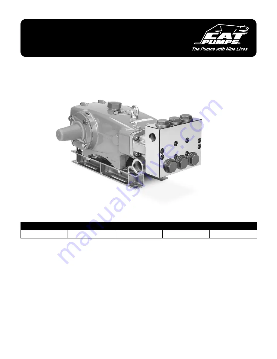
SERVICE MANUAL
3570 SERIES PLUNGER PUMPS
PUMP MODELS INCLUDED
3570
3570S
3570C
Page 1: ...www catpumps com Product Quality Reliability and Support You Expect SERVICE MANUAL 3570 SERIES PLUNGER PUMPS PUMP MODELS INCLUDED 3570 3570S 3570C ...
Page 2: ...tes 26 Diagnosis and Maintenance 28 Table of Contents IMPORTANT SAFETY INSTRUCTIONS It is the responsibility of the user to read and understand all instructions important safeguards and safety precautions before operating or servicing any pump Failure to do so may result in property damage personal injury or death GENERAL SAFETY INFORMATION AND SYMBOLS Payspecialattentiontothefollowingsignalwords ...
Page 3: ... to Lock Out and Tag Out procedures for electrical equipment 2 Before commencing pump service turn power supply off turn water supply off squeeze trigger on gun to relieve system pressure 3 For mobile equipment be sure engines and hydraulics are turned off and secured to avoid accidental start 4 Do not operate with safety guards removed 5 Always use safety guards on all belt drives couplings and s...
Page 4: ...e and hold gun with both hands to control kick back A IMPROPER USE OF FITTINGS HAZARD Donotoperatethepumpwithimproperly connected sized wornorloosefittings pipesorhoses Operatingthepumpundertheseconditions couldresultinpersonalinjuryandpropertydamage 1 Ensure all fittings pipes and hoses are properly rated for the maximum pressure rating and flow of the pump 2 Check all fittings and pipes for crac...
Page 5: ...ld head of the pump 2 Ensure oil is filled to the center red dot on sight gauge for forward rotation 3 If reverse rotation is unavoidable ensure oil is filled to slightly above center red dot on sight gauge C BELT TENSION HAZARD Donotoperatepumpwithexcessivebelttension Excessivebelttensionmaydamagethepump sbearingsorreducehorsepower 1 Rotate pump crankshaft before starting to ensure shaft and bear...
Page 6: ...e and maintenance cycle Most system failures are not due to the pump but fail because of other system components The Preventative Maintenance Check List on page 24 provides a summary of the various system maintenance concerns for all high pressure systems The seals on our pumps operating under normal conditions will perform for a minimum of 1500 hours with most lasting much longer The valves typic...
Page 7: ...ls Needed 1 10 mm Hex Wrench 2 12 mm Hex Wrench 3 41 mm Socket with Ratchet 4 2x Flat Tip Screwdrivers 5 Pick 6 NeedleNosePliers 7 M10 x 1 5 Bolt 8 Adjustable Wrench 9 Reverse Pliers PN 30696 10 21 mm Combination Wrench 11 Rubber Mallet 12 Oil Bubble Gauge Tool PN 44050 13 Lubricating Oil 14 Liquid Thread Sealant Seal Valve Kit Pump Diagram VALVE KITS PN 76794 Qty 2 10 1 2 SEAL KIT 31039 Qty 1 5 4...
Page 8: ...0mmhexwrenchtoremovetheeight 8 hexsockethead HSH screwsfromthe manifold 1 02 Rotatethecrankshaftwithanadjustable wrenchtocreateseparationbetweenthe inletandthedischargemanifolds 1 03 Inserttwo 2 flattipscrewdriversonopposite sidestoprythedischargemanifoldawayfrom theinletmanifold 1 04 Supportthedischargemanifoldfrom underneath Usingarubbermallet tapthe manifoldtoseparatefromtheinletmanifold andrem...
Page 9: ...ectforcuts nicksordamage 1 17 Rotatethecrankshaftwithanadjustable wrenchtocreateseparationbetweenthe manifoldandcrankcase 1 12 InspecttheV packingcylinderboresto ensuresealingsurfacesaresmoothandfree fromcorrosion 1 15 Usingapick removetheinletmanifold O rings 1 18 Inserttwo 2 flattipscrewdriversonopposite sidestoprythemanifoldawayfromthe crankcase 1 13 Usingapick removetherearV packing cylinderO ...
Page 10: ...rmallet tapthemanifoldtoseparate fromthecrankcaseandremovecompletely 1 22 Inspectthemanifoldborestoensuresealing surfacesaresmoothandfreefromcorrosion 1 25 Ifthelow pressuresealadaptersstayonthe plungers wipeplungerscleanandapplya lightoil 1 20 Placetheinletmanifoldonaflatsurfacewith theV packingcylinderboresfacingupwards 1 23 Flipthemanifoldoversothelow pressure sealadaptersarefacingupwards 1 26 ...
Page 11: ...pof thelargeboreendoftheV packingcylinders withthelow pressuresealfacingdown 1 31 Inspecttheinsidediameterofthelow pressuresealadapterstoensuresealing surfacesaresmoothandfreefromcorrosion 1 29 Usingasocketthathasthesamediameteras thelow pressuresealadapterbore pushthe low pressuresealsoutoftheadapters 1 32 Usingapick removetheO ringsfromthe low pressuresealadapters Inspectforcuts nicksordamage Se...
Page 12: ... Seals 1 37 Usinga21mmcombinationwrench loosen theplungerretainers 1 40 Removetheplungerretainersfromthe plungersandinspecttheO ringsandbackup ringsfordamage 1 38 Beforecompletelyremovingtheplunger retainers stopandpushtheplungers towardsthedriveendtobreakloosefromthe retainers 1 41 Usingapick removetheplungerretainer O ringsfromtheplungerretainers 1 39 Removetheplungersandretainers 1 42 Inspectce...
Page 13: ...ngerretainerO rings 1 50 PlaceadropofLoctite 242 onthethreaded endsoftheplungerrods 1 51 Threadplungerassembliesintoplungerrods byhand andtorqueto220in lbs 18ft lbsor 24Nm 1 48 Lookforsteppedsideofplungers Thesesides gotowardsthepumpcrankcase 1 44 Installbarrierslingerswithdishsidefacing awayfromcrankcase 1 45 Installkeyholewashers Theslotcanfaceany direction Loctite and 242 are registered tradema...
Page 14: ...Usingasocketwiththesamediameterasthe low pressureseals tapthelow pressureseals allthewayintotheadapters 1 59 Applyalubricanttotheoutsidesurfacesof thelow pressuresealadapterO rings 1 60 Pressthelow pressuresealadaptersintothe inletmanifoldwiththegroovedsidesofthe low pressuresealsfacingdown 1 61 FlipthemanifoldoversotheV packingspacer boresarefacingupwards 1 53 Installthelow pressuresealwashersint...
Page 15: ...ylinders 1 67 InstallthesecondV packingswiththe groovedsidesalsofacingdown 1 68 Installthefemaleadapterswithgroovedsides facingdownintotheV packingcylinders 1 69 InstallV packingspacerwiththesmaller diametersidesfacingdownandpressthem intoplace 1 65 InstallthemaleadaptersintotheV packing cylinderswiththeflatsidesfacingdown NOTICE There are two O rings for each V packing cylinder The thicker O ring...
Page 16: ...cylinderassembliesintothe inletmanifoldboreswiththebackupring endsfacingupwards 1 73 Installinletmanifoldbyhand ensuringeven alignment 1 76 Installfour 4 HSHscrewsbyhand 1 74 Usearubbermallettotapmanifoldonthe restoftheway 1 75 PlaceadropofLoctite 242 onthethreadsof inletmanifoldscrews 1 77 Usinga12mmhexwrench tightenhex headscrewsusingappropriatecross pattern forevenalignment Torqueto480in lbs 40...
Page 17: ...bbermallettotapmanifoldonthe restoftheway 1 82 Installeight 8 HSHscrewsbyhand Servicing the Seals 1 83 WatchbackupringsonV packingcylindersto ensuretheydonotcomeoutoftheirgrooves whiletighteningdischargemanifoldinto place 1 84 Usinga10mmhexwrench tightenhexhead screwsusingappropriatecross patternfor evenalignment Torqueto355in lbs 30ft lbs or40Nm 1 85 Rotatecrankshaftwithadjustablewrench toensurep...
Page 18: ...nifold 2 02 Usingapick removeO ringsandbackup ringsfromvalveplugs 2 01 Usea41mmsocketwithratchettoremove thevalveplugsfrompumpmanifold 2 03 InspectvalveplugO ringsandbackuprings forcuts nicksordamage NOTES Two 2 valve kits are required to repair the pump Discharge and inlet valve assemblies are identical use procedure below for disassembly and reassembly of discharge and inlet valves NOTICE If the...
Page 19: ...attipscrewdriveringapandtwistto completelyseparate VALVE REMOVAL VALVE DISASSEMBLY 2 08 Inserttwo 2 flattipscrewdriversthrough springretainersjustabovevalves Twistto createasmallgapbetweenvalveretainers andvalveseats NOTICE Valve assemblies can be disassembled for inspection and servicing then reassembled If replacing complete valve kit assemblies skip to Valve Installation 2 22 NOTICE Pitting on ...
Page 20: ...ngapick removeO ringsandbackup ringsfromvalveseats 2 15 InspectvalveseatO ringsandbackuprings forcuts nicks ordamage 2 17 Placevalvesontovalveseatswithtapered surfacesfacingdown 2 20 Usingarubbermallet lightlytapspring retainersintoplace 2 18 Placespringontoconcavesidesofvalves 2 21 ReplacevalveseatO ringsintothetopof thegroove thenbackupringsatthebottom VALVE DISASSEMBLY VALVE REASSEMBLY Servicin...
Page 21: ...Torqueto1305in lbs 109ft lbs or148Nm Loctite and 242 are registered trademarks of the Henkel Corporation 2 23 Insertvalveassembliesintomanifoldand pressintoplace 2 28 PlaceadropofLoctite 242 onthethreadsof valveplugs 2 24 Installthespringwashersontopofthevalve assemblies 2 26 ReplacevalveplugO ringsintothetopofthe valvepluggroove thenbackupringsatthe bottom 2 25 Installthecoilspringsontopofthespri...
Page 22: ... Oil Bubble Gauge indicates the presence of water in the crankcase A water oil mix does not provide enough lubrication to the components in the drive end and will cause damage This damage can occur on the plunger rods or the crankshaft and connecting rods Also without a layer of oil on the drive end components oxidation and rust will form on the bearings and crankshaft If contamination is suspecte...
Page 23: ...eries Plunger Pumps 23 763 780 5440 techsupport catpumps com www catpumps com Oil Bubble Gauge Check oil level color for contamination leaking oil Crankshaft Oil Seals Check for leaking oil Drain Plug Check for leaking oil ...
Page 24: ...or OilLeaks Plumbing Belts Pulley Accessories Seals Valves 1 1 2 3 Cat Pumps recommends using our custom blend premium grade hydraulic oil formulated to meet Cat Pumps specifications For best results perform an initial oil change after the first 50 hours of operation and every 500 hours thereafter Every system operates under different conditions Past performance and maintenance history are the bes...
Page 25: ...d Screws M10 17 mm Combination Wrench 220 18 0 24 0 Bubble Oil Gauge M28 Oil Gauge Tool 44050 45 3 8 5 0 TECHNICAL BULLETIN REFERENCE CHART NO SUBJECT MODELS 002 Inlet Pressure vs Water Temperature All Models 024 Lubrication of Low Pressure Seals All Models 035 Servicing Crankcase Section Roller Bearing Models 7CP 7PFR 68PFR Plunger Pumps 036 Identifying Your Pump All Models 043 Servicing the Low ...
Page 26: ...SERVICE MANUAL 3570 Series Plunger Pumps 26 763 780 5440 techsupport catpumps com www catpumps com Notes ...
Page 27: ...SERVICE MANUAL 3570 Series Plunger Pumps 27 763 780 5440 techsupport catpumps com www catpumps com Notes ...
Page 28: ...eal kit Increase frequency of service Knocking noise Inlet supply Inadequate inlet liquid supply Check liquid supply Increase line size or pressurize Bearing Broken or worn bearing Replace bearing Oil leak Crankcase oil seal Worn crankcase oil seal Replace crankcase oil seal Crankshaft oil seal and O ring Worn crankshaft oil seal or O ring on bearing cover Remove bearing cover and replace O ring a...