3 - CONTROLS/INSTRUMENTS
LEFT-HAND SIDE CONTROLS
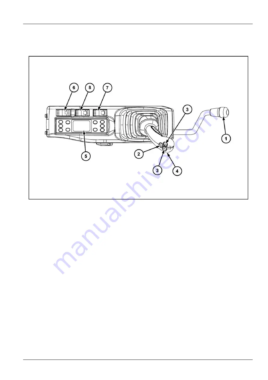
Left-hand control arm
714DB4B6B
1
1. Function cancellation lever
The shape of the function cancellation lever was de-
signed to prevent the operator from leaving the op-
erator’s compartment without having raised the lever
beforehand.
2. Horn
To sound the horn, press the end of the left-hand con-
trol lever.
NOTICE:
Always sound the horn before operating the
machine.
3. Option control (if equipped)
4. Cab radio mute control
Located below the control lever, this control is used
to mute the sound without having to operate the cab
radio.
Press and release the control to mute the sound.
Press once again on the control and release, the
sound is restored.
NOTE:
With the engine stopped, if the sound is muted,
it will still be active when the engine is restarted.
5. Heating, ventilation or air conditioning control (Refer
to page
3-52
6. Emergency shut down switch
This control enables the engine to be shut down in
emergency or when it is not possible to shut it down
by means of the ignition key.
Press on the front of the control, the engine stops, the
audible warning device sounds, the control indicator
lamp comes on and the message "Engine stop" is dis-
played, refer to page
3-19
.
To start the engine again, press on the back of the
control once more and then turn the ignition key to
start the engine.
NOTICE:
This switch should only be used in case of
an emergency.
7. Quick coupler locking and unlocking control switch
(optional)
(Refer to page
3-56
).
8. Free swing switch (optional)
The switch to choose the swing stopping condition.
In
“Off”
position the swing stops immediately.
In
“On”
position the swing continues to turn slightly.
NOTE:
When the engine is started, it is in the
“Off”
position.
NOTE:
When it is
“On”
and used on a slope, the
swing becomes hard to stop.
(The swing parking
brake does not work automatically). If the switch is
3-49
Summary of Contents for CX145C SR
Page 6: ......
Page 18: ...1 GENERAL INFORMATION 1 12 ...
Page 29: ...2 SAFETY INFORMATION E5054225_TU 4 2 11 ...
Page 132: ...3 CONTROLS INSTRUMENTS 3 82 ...
Page 160: ...4 OPERATING INSTRUCTIONS 4 Operate the arm control to unhook the tool KKZVLU 024A 14 4 28 ...
Page 180: ...4 OPERATING INSTRUCTIONS 4 48 ...
Page 206: ...6 MAINTENANCE Offset boom pin 10 07C803C9 17 6 16 ...
Page 207: ...6 MAINTENANCE Arm backhoe bucket 375EFD72 18 AB1F527A 19 6 17 ...
Page 298: ...8 SPECIFICATIONS Offset maximum left EACB5F36 6 See next page for the value 8 14 ...
Page 300: ...8 SPECIFICATIONS 8 16 ...


