background image

Engine - Engine and crankcase

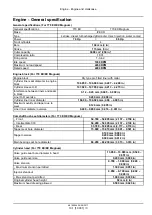
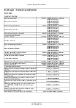
Crankcase - General specification

Crank gear

Crankshaft - Bearings

Main journal diameter

79.791 – 79.810 mm

(

3.141 – 3.142 in

)

Main journal undersize

0.254 mm

(

0.010 in

)

0.508 mm

(

0.020 in

)

0.762 mm

(

0.030 in

)

1.016 mm

(

0.040 in

)

Main bearing wall thickness

2.168 – 2.178 mm

(

0.085 – 0.086 in

)

Main bearing under size

0.254 mm

(

0.010 in

)

0.508 mm

(

0.020 in

)

0.762 mm

(

0.030 in

)

1.016 mm

(

0.040 in

)

Main journal clearance in bearings

0.034 – 0.103 mm

(

0.001 – 0.004 in

)

• Maximum wear clearance

0.180 mm

(

0.007 in

)

Crankpin diameter

63.725 – 63.744 mm

(

2.509 – 2.510 in

)

Crankpin undersize

0.254 mm

(

0.010 in

)

0.508 mm

(

0.020 in

)

0.762 mm

(

0.030 in

)

1.016 mm

(

0.040 in

)

Big end bearing wall thickness

1.805 – 1.815 mm

(

0.071 – 0.071 in

)

Big end bearing undersize

0.254 mm

(

0.010 in

)

0.508 mm

(

0.020 in

)

0.762 mm

(

0.030 in

)

1.016 mm

(

0.040 in

)

Crankpin clearance in big end bearing

0.033 – 0.087 mm

(

0.001 – 0.003 in

)

• Maximum wear clearance

0.180 mm

(

0.007 in

)

Crankshaft thrust washer thickness

3.378 – 3.429 mm

(

0.133 – 0.135 in

)

Thrust washer oversize

0.127 mm

(

0.005 in

)

0.254 mm

(

0.508 in

)

0.508 mm

(

0.020 in

)

Width of main bearing housing over thrust washers

31.766 – 31.918 mm

(

1.251 – 1.257 in

)

Length of corresponding main journal

32.000 – 32.100 mm

(

1.260 – 1.264 in

)

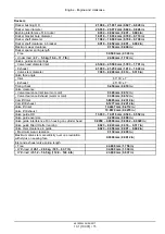
Crankshaft end float

0.082 – 0.334 mm

(

0.003 – 0.013 in

)

• Maximum wear clearance

0.400 mm

(

0.016 in

)

Maximum main journal and crankpin ovality or taper after
grinding

0.010 mm

(

0.00039 in

)

Maximum main journal and crankpin ovality or taper due
to wear

0.050 mm

(

0.0019 in

)

Maximum main journal misalignment crankshaft resting
on end journals

0.010 mm

(

0.00039 in

)

Maximum misalignment of crankpins relative to main
journals (in either direction)

0.25 mm

(

0.00098 in

)

Tolerance from outer crankpin edge to crankshaft center
line

±

0.10 mm

(

0.0039 in

)

Maximum crankshaft flange run-out with gauge stylus,
over

108.000 mm

(

4.252 in

) diameter (total gauge

reading)

0.0250 mm

(

0.00098 in

)

Maximum flywheel seat eccentricity relative to main
journals (total gauge reading)

0.0400 mm

(

0.00157 in

)

Side clearance of connecting rod and crankshaft

0.06 – 0.10 mm

(

0.002 – 0.004 in

)

48190544 26/09/2017

10.1 [10.001] / 12

Summary of Contents for 770 EX

Page 1: ...SERVICE MANUAL English September 2017 Part number 48190544 2017 CNH Construction Equipment India Pvt Ltd All rights reserved 770 EX 770 EX MAGNUM Tractor Loader ...

Page 2: ...1 5 Front axle system 25 25 100 Powered front axle 25 1 25 102 Front bevel gear set and differential 25 2 25 108 Final drive hub steering knuckles and shafts 25 3 25 400 Non powered front axle 25 4 Rear axle system 27 27 100 Powered rear axle 27 1 27 106 Rear bevel gear set and differential 27 2 27 124 Final drive hub steering knuckles and shafts 27 3 Brakes and controls 33 33 202 Hydraulic servic...

Page 3: ...ntrol 41 1 41 200 Hydraulic control components 41 2 41 216 Cylinders 41 3 Wheels 44 44 511 Front wheels 44 1 44 520 Rear wheels 44 2 44 AAA Wheels generic sub group 44 3 Cab climate control 50 50 100 Heating 50 1 50 200 Air conditioning 50 2 Electrical systems 55 55 100 Harnesses and connectors 55 1 55 201 Engine starting system 55 2 55 301 Alternator 55 3 55 518 Wiper and washer system 55 4 Front...

Page 4: ... 90 150 Cab 90 1 90 154 Cab doors and hatches 90 2 90 156 Cab windshield and windows 90 3 90 100 Engine hood and panels 90 4 48190544 26 09 2017 Find manuals at https best manuals com ...

Page 5: ...INTRODUCTION 48190544 26 09 2017 1 Find manuals at https best manuals com ...

Page 6: ...otice regarding equipment servicing 9 Basic instructions 10 Basic instructions Fuse and relay locations 11 Basic instructions 12 Basic instructions 14 Basic instructions Shop and assembly 15 Torque Minimum tightening torques for normal assembly 17 Torque Standard torque data for hydraulics 22 Abbreviation Measurements 24 Capacities 26 48190544 26 09 2017 2 Find manuals at https best manuals com ...

Page 7: ...y CAUTION indicates a hazardous situation that if not avoided could result in minor or moderate injury FAILURE TO FOLLOW DANGER WARNING AND CAUTION MESSAGES COULD RESULT IN DEATH OR SERIOUS INJURY Machine safety NOTICE Notice indicates a situation that if not avoided could result in machine or property damage Throughout this manual you will find the signal word Notice followed by special instructi...

Page 8: ...and filters must be disposed of in compliance with environmental standards and regulations Contact your Dealer with any questions regarding the service and maintenance of this machine Use this manual with the operator s manual to understand and perform the complete service procedures Read the safety decals and information decals on the machine Read the Operator s Manual and safety manual Understan...

Page 9: ...uctile iron parts on this machine Before you weld cut or drill holes on any part of this machine make sure the part is not cast ductile iron See your dealer if you do not know if a part is cast ductile iron The following items are examples of cast ductile iron parts There may also be other parts made of cast ductile iron that are not on the list below two wheel drive steering link dump links front...

Page 10: ... weld cut or drill holes on any part of this machine make sure the part is not cast ductile iron See your dealer if you do not know if a part is cast ductile iron The following are cast ductile iron parts two wheel drive steering link dump links front axle bucket linkage Air conditioning A C compressor mounting bracket Unauthorized modifications to cast ductile iron parts can cause injury or death...

Page 11: ...e ground with the bottom of the loader bucket parallel to the surface 3 Place the direction control lever and the transmission in neutral 4 If you need to open the hood to perform service raise the loader arms and install the support strut 5 Shut down the engine 6 Place a Do Not Operate tag on the key switch so that it is visible to other workers or remove the key 48190544 26 09 2017 7 ...

Page 12: ...e spillage In general avoid skin contact with all fuels oils acids solvents etc Most of them contain substances that may be harmful to your health Modern oils contain additives Do not burn contaminated fuels and or waste oils in ordinary heating systems Avoid spillage when draining off used engine coolant mixtures engine gearbox and hydraulic oils brake fluids etc Do not mix drained brake fluids o...

Page 13: ...ty for damages caused by parts and or components not approved by the manufacturer including those used for the servicing or repair of the product manufactured or marketed by the manufacturer In any case no warranty is given or attributed on the product manufactured or marketed by the manufacturer in case of damages caused by parts and or components not approved by the manufacturer The information ...

Page 14: ...proof goggles and protective clothing gloves and aprons Wash hands after handling Failure to comply could result in death or serious injury W0006A Do not run the engine with the alternator wires disconnected Before using an electric welder disconnect the alternator wires instrument cluster and batteries Do not use a steam cleaner or a cleaning solvent to clean the alternator Keep the battery vents...

Page 15: ... Fuse rating Fuse details 1 15 A Front work light 2 10 A 12 V power output 3 15 A Rear work light 4 15 A Horn hazard light control 5 10 A Cabin fan radio 6 10 A Installer ignition 7 10 A Wiper 8 15 A Driving lamp LOW 9 15 A Driving lamp HIGH 10 10 A Cabin dome light 11 20 A HVAC If fitted 12 10 A Loader self level 13 10 A Side shift lock 14 10 A Cluster 15 10 A Speedometer 16 10 A Stop lamps 17 10...

Page 16: ...support strut Failure to comply could result in death or serious injury W0230A Raise and support loader lift arms 1 Empty the loader bucket 2 Raise the loader lift arms to the maximum height 3 Shut down the engine PTIL17TLB0173AA 1 4 Remove the retaining pin 5 Lower the support strut onto the cylinder rod 6 Install the retaining pin PTIL17TLB0174AA 2 7 Start the engine 8 Slowly lower the lift arms...

Page 17: ... longer rests on the cylinder 2 Shut down the engine PTIL17TLB0173AA 4 3 Remove the retaining pin from the support strut 4 Raise the support strut up to the storage position and secure with the retaining pin as shown PTIL17TLB0174AA 5 5 Start the engine 6 Lower the loader to the ground 48190544 26 09 2017 13 ...

Page 18: ...o release the hood latch PTIL13TLB1558AB 1 3 Lift the hood and rotate forward PTIL17TLB0164AA 2 NOTICE To avoid damage to the hood parts always close the hood before moving the loader Close the hood 1 Lower the hood 2 Turn the handle 1 clockwise to lock the hood latch PTIL13TLB1558AB 3 48190544 26 09 2017 14 ...

Page 19: ...on tool Do not tap the seal with a hammer or mallet 6 While you insert the seal check that the seal is perpendicular to the seat When the seal settles make sure that the seal makes contact with the thrust element if required 7 To prevent damage to the seal lip on the shaft position a protective guard during installation operations O ring seals Lubricate the O ring seals before you insert them in t...

Page 20: ... ground cable from the machine battery The electronic monitoring system and charging system will be damaged if this is not done 5 Remove the battery ground cable Reconnect the cable when you complete welding Special tools WARNING Battery acid causes burns Batteries contain sulfuric acid Avoid contact with skin eyes or clothing Antidote external Flush with water Antidote eyes flush with water for 1...

Page 21: ...in 25 N m 217 lb in 26 N m 234 lb in 35 N m 311 lb in 17 N m 151 lb in 24 N m 212 lb in M10 37 N m 27 lb ft 49 N m 36 lb ft 52 N m 38 lb ft 70 N m 51 lb ft 33 N m 25 lb ft 48 N m 35 lb ft M12 64 N m 47 lb ft 85 N m 63 lb ft 91 N m 67 lb ft 121 N m 90 lb ft 58 N m 43 lb ft 83 N m 61 lb ft M16 158 N m 116 lb ft 210 N m 155 lb ft 225 N m 166 lb ft 301 N m 222 lb ft 143 N m 106 lb ft 205 N m 151 lb ft...

Page 22: ...9 N m 343 lb in 18 N m 163 lb in 27 N m 240 lb in M10 40 N m 30 lb ft 54 N m 40 lb ft 57 N m 42 lb ft 77 N m 56 lb ft 37 N m 27 lb ft 53 N m 39 lb ft M12 70 N m 52 lb ft 93 N m 69 lb ft 100 N m 74 lb ft 134 N m 98 lb ft 63 N m 47 lb ft 91 N m 67 lb ft M16 174 N m 128 lb ft 231 N m 171 lb ft 248 N m 183 lb ft 331 N m 244 lb ft 158 N m 116 lb ft 226 N m 167 lb ft M20 350 N m 259 lb ft 467 N m 345 lb...

Page 23: ...ft 7 16 48 N m 36 lb ft 65 N m 48 lb ft 68 N m 50 lb ft 91 N m 67 lb ft 50 N m 37 lb ft 71 N m 53 lb ft 1 2 74 N m 54 lb ft 98 N m 73 lb ft 104 N m 77 lb ft 139 N m 103 lb ft 76 N m 56 lb ft 108 N m 80 lb ft 9 16 107 N m 79 lb ft 142 N m 105 lb ft 150 N m 111 lb ft 201 N m 148 lb ft 111 N m 82 lb ft 156 N m 115 lb ft 5 8 147 N m 108 lb ft 196 N m 145 lb ft 208 N m 153 lb ft 277 N m 204 lb ft 153 N...

Page 24: ...85 lb ft 153 N m 113 lb ft 74 N m 55 lb ft 104 N m 77 lb ft 9 16 117 N m 86 lb ft 156 N m 115 lb ft 165 N m 122 lb ft 221 N m 163 lb ft 106 N m 78 lb ft 157 N m 116 lb ft 5 8 162 N m 119 lb ft 216 N m 159 lb ft 228 N m 168 lb ft 304 N m 225 lb ft 147 N m 108 lb ft 207 N m 153 lb ft 3 4 287 N m 212 lb ft 383 N m 282 lb ft 405 N m 299 lb ft 541 N m 399 lb ft 261 N m 193 lb ft 369 N m 272 lb ft 7 8 4...

Page 25: ...8 4 Grade Identification Grade Corner Marking Method 1 Flats Marking Method 2 Clock Marking Method 3 Grade A No Notches No Mark No Marks Grade B One Circumferential Notch Letter B Three Marks Grade C Two Circumferential Notches Letter C Six Marks 48190544 26 09 2017 21 ...

Page 26: ... N m 10 15 lb ft 6 9 5 mm 3 8 in 9 16 18 29 33 N m 21 24 lb ft 20 27 N m 15 20 lb ft 8 12 7 mm 1 2 in 3 4 16 47 54 N m 35 40 lb ft 34 41 N m 25 30 lb ft 10 15 9 mm 5 8 in 7 8 14 72 79 N m 53 58 lb ft 47 54 N m 35 40 lb ft 12 19 1 mm 3 4 in 1 1 16 12 104 111 N m 77 82 lb ft 81 95 N m 60 70 lb ft 14 22 2 mm 7 8 in 1 3 16 12 122 136 N m 90 100 lb ft 95 109 N m 70 80 lb ft 16 25 4 mm 1 in 1 5 16 12 14...

Page 27: ...g ORFS fittings thoroughly clean both flat surfaces of the fittings 1 and lubricate the O ring 2 with light oil Make sure both surfaces are aligned properly Torque the fitting to specified torque listed throughout the repair manual NOTICE If the fitting surfaces are not properly cleaned the O ring will not seal properly If the fitting surfaces are not properly aligned the fittings may be damaged a...

Page 28: ...und per inch lb in Frequency megahertz MHz megahertz MHz kilohertz kHz kilohertz kHz hertz Hz hertz Hz Frequency Rotational r min r min ª revolution per minute rpm revolution per minute rpm Length kilometer km mile mi meter m foot ft centimeter cm inch in millimeter mm inch in micrometer µm Mass kilogram kg pound lb gram g ounce oz milligram mg Power kilowatt kW horsepower Hp watt W Btu per hour B...

Page 29: ...s foot per second ft s millimeter per second mm s inch per second in s meter per minute m min foot per minute ft min Volume includes Capacity cubic meter m cubic yard yd cu yd liter l cubic inch in liter l US gallon US gal UK gallon UK gal US quart US qt UK quart UK qt milliliter ml fluid ounce fl oz Volume per time includes Discharge and Flow rate cubic meter per minute m min cubic foot per minut...

Page 30: ...AE 30 CASE AXLPOWER 9 00 l 2 38 US gal 5 Engine oil BS III API CI4 SAE 15W 40 Servo Pride Supreme 11 00 l 2 91 US gal 6 Brake fluid ISO 7308 Servo Transtrac HVI 0 67 l 0 18 US gal 7 Hydraulic oil ISO VG 68 IS 10522 CASE HYDRAPOWER Tank 65 l 17 17 US gal System 65 l 17 17 US gal Total 130 l 34 34 US gal 8 Coolant COOL POWER 20 l 5 28 US gal 9 Grease EP GREASE GRADE 2 IS 7623 ServoGem EP2 1 7 kg 3 7...

Page 31: ...SERVICE MANUAL Engine 770EX Magnum 770EX 48190544 26 09 2017 10 ...

Page 32: ...Contents Engine 10 10 001 Engine and crankcase 10 1 10 254 Intake and exhaust manifolds and muffler 10 2 10 400 Engine cooling system 10 3 48190544 26 09 2017 10 ...

Page 33: ...Engine 10 Engine and crankcase 001 770EX Magnum 770EX 48190544 26 09 2017 10 1 10 001 1 ...

Page 34: ...cification 3 Torque 4 Sealing 5 Special tools 5 Crankcase General specification 12 FUNCTIONAL DATA Engine Static description 16 SERVICE Engine and crankcase Service instruction 22 Engine Remove 23 Install 26 DIAGNOSTIC Engine Troubleshooting 29 48190544 26 09 2017 10 1 10 001 2 ...

Page 35: ...nder liner inner diameter 104 00 104 024 mm 4 09 4 095 in Maximum ovality and taper due to wear 0 120 mm 0 005 in Liner inner diameter oversize 0 400 0 800 mm 0 016 0 031 in Camshaft bush seat diameters For 770 EX EX Magnum Front 54 780 54 805 mm 2 157 2 158 in Intermediate C33 54 280 54 305 mm 2 137 2 138 in Rear 53 780 53 805 mm 2 117 2 118 in Tappet seat bore diameter 15 000 15 018 mm 0 591 0 5...

Page 36: ...re 15 Intake closing after bottom dead centre 45 Exhaust opening before bottom dead centre 56 Exhaust closing after top dead centre 26 Valve inserts For 770 EX EX Magnum Valve guide OD 13 933 14 016 mm 0 549 0 552 in Valve guide oversize 0 200 mm 0 008 in Valve guide interference fit in housing cylinder head 0 0050 0 0500 mm 0 0002 0 0020 in Valve guide fitted ID after reaming 8 023 8 043 mm 0 316...

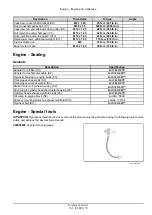
Page 37: ...ication Adopter for oil filter S1 LOCTITE 270 Adopter for tachometer cable S2 LOCTITE 243 Flywheel housing to engine block S3 LOCTITE 510 Timing gear case studs S4 LOCTITE 270 Timing gear cover dowel pin S5 LOCTITE 270 Starter motor to flywheel housing S6 LOCTITE 510 Allen plug in cylinder head thermostat housing S7 LOCTITE 243 Cylinder head exhaust manifold studs s8 LOCTITE 270 Oil sump to engine...

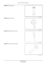
Page 38: ...00301 Engine stand PTIL14TLB0102AA 2 380200415 Support PTIL14TLB0103AA 3 380000302 Cylinder head valve spring compressor PTIL14TLB0104AA 4 380200447 Puller FIP gear crank pulley hub PTIL14TLB0105AA 5 48190544 26 09 2017 10 1 10 001 6 ...

Page 39: ...48 Sump locating pin PTIL14TLB0106AA 6 380200449 Adaptor FIP timing PTIL14TLB0107AA 7 380000232 Tappet adjusting screw driver PTIL14TLB0108AA 8 380200450 Crankshaft front seal installer PTIL14TLB0109AA 9 48190544 26 09 2017 10 1 10 001 7 ...

Page 40: ...il pressure gauge with adaptor PTIL14TLB0110AA 10 380000215 Nozzle tester PTIL14TLB0111AA 11 380200451 Installer main oil seal PTIL14TLB0112AA 12 380000549 Sliding hammer Injector removal PTIL14TLB0113AA 13 48190544 26 09 2017 10 1 10 001 8 ...

Page 41: ...00452 Remover filters PTIL14TLB0114AA 14 380200453 Wrench to remove solenoid switch PTIL14TLB0115AA 15 380200454 FIP nut remover PTIL14TLB0116AA 16 380200471 Injector sleeve puller PTIL14TLB0124AA 17 48190544 26 09 2017 10 1 10 001 9 ...

Page 42: ... 380000830 Guide socket PTIL14TLB0117AA 18 380000228 Dial gauge PTIL14TLB0123AA 19 380000834 Injector sleeve installer PTIL14TLB0118AA 20 380000833 Cutter Injector holder seat PTIL14TLB0119AA 21 48190544 26 09 2017 10 1 10 001 10 ...

Page 43: ... crankcase 380000219 Valve guide installer remover PTIL14TLB0120AA 22 380000242 Valve guide installer PTIL14TLB0121AA 23 380000229 Dial gauge holder tool Pump timing PTIL14TLB0122AA 24 48190544 26 09 2017 10 1 10 001 11 ...

Page 44: ... thickness 3 378 3 429 mm 0 133 0 135 in Thrust washer oversize 0 127 mm 0 005 in 0 254 mm 0 508 in 0 508 mm 0 020 in Width of main bearing housing over thrust washers 31 766 31 918 mm 1 251 1 257 in Length of corresponding main journal 32 000 32 100 mm 1 260 1 264 in Crankshaft end float 0 082 0 334 mm 0 003 0 013 in Maximum wear clearance 0 400 mm 0 016 in Maximum main journal and crankpin ovali...

Page 45: ... Maximum wear clearance 0 300 mm 0 012 in Piston oversize range 0 600 mm 0 024 in Piston stand out with respect to head at TDC 0 430 0 840 mm 0 017 0 033 in Piston pin diameter 37 983 37 990 mm 1 495 1 496 in Piston pin seat bore in piston 38 000 38 006 mm 1 496 1 496 in Piston pin clearance in piston 0 0100 0 0230 mm 0 0004 0 0009 in Piston pin clearance in small end bushing 0 0140 0 0310 mm 0 00...

Page 46: ...ing O D Front 54 875 54 930 mm 2 160 2 163 in Intermediate 54 375 54 430 mm 2 141 2 143 in Rear 53 875 53 930 mm 2 121 2 123 in Bushing interference fit in housing 0 070 0 150 mm 0 003 0 006 in Camshaft bushing fitted ID after reaming Front 51 080 51 130 mm 0 003 0 006 in Intermediate 50 580 50 630 mm 1 991 1 993 in Rear 50 080 50 130 mm 1 972 1 974 in Camshaft journal diameter Front 50 970 51 000...

Page 47: ...g check 0 450 mm 0 018 in Valve clearance Valve clearance Inlet warm or cold 0 300 mm 0 012 in Valve clearance Exhaust warm or cold 0 300 mm 0 012 in Cam lift Inlet 5 8885 mm 0 2318 in Cam lift Exhaust 6 1277 mm 0 2412 in Valve lift Inlet 10 4437 mm 0 4112 in Valve lift Exhaust 10 8679 mm 0 4279 in Valve guide OD 13 933 14 016 mm 0 549 0 552 in Valve guide oversize 0 200 mm 0 008 in Valve guide in...

Page 48: ...value rotators valve clearance is maintained by adjustment of the self locking adjusting screw mounted in each of the rocker arms Camshaft assembly The camshaft runs in 3 replaceable bushes The camshaft drive gear is in mesh with and driven by the camshaft idler gear which is driven by the crankshaft timing gear Camshaft end thrust is controlled by a thrust plate bolted to the block and located be...

Page 49: ...stion chamber being recessed in the piston crowns Each piston has two compression rings and one oil control ring to reduce the friction and increase positive seating All rings are located above the piston pin Manifolds The cross flow design aluminum intake and cast iron exhaust manifolds are on opposite sides of the cylinder head This is designed to maintain balanced heat distribution within the c...

Page 50: ...r is mounted externally to its support housing on the left hand side of the engine Oil flows from the filter to the main oil gallery which runs the length of the cylinder block which also intersects the camshaft follower chamber The main gallery also supplies oil to the crankshaft main bearings connecting rods both big and small ends and timing gear bushes The inner side of the pistons and pins ar...

Page 51: ...This as a preview PDF file from best manuals com Download full PDF manual at best manuals com ...

Reviews: