


CARVER
®
OPERATION, INSTALLATION AND MAINTENANCE MANUAL
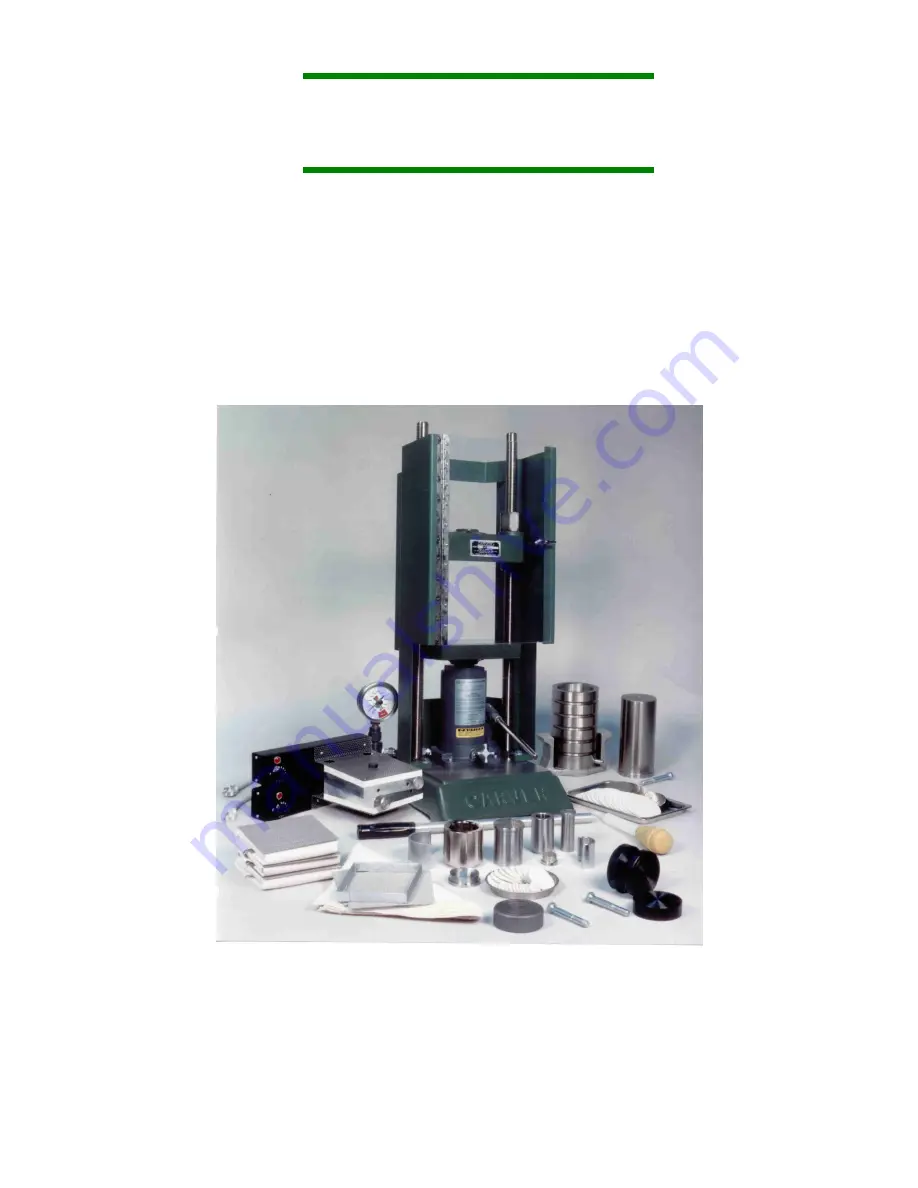
TWO and FOUR POST MANUAL HYDRAULIC PRESSES
HEATED AND UNHEATED
IMPORTANT:
PLEASE READ CAREFULLY BEFORE INSTALLING OR OPERATING THIS EQUIPMENT
CARVER, INC.
1569 Morris Street, P.O. Box 544
Wabash, IN 46992-0544
PH: 260-563-7577 FAX: 260-563-7625
Summary of Contents for 12-10
Page 27: ...Carver Inc 4 9...
Page 39: ...Carver Inc 10 2 WARNING TAGS cont SHOCKING HAZARD HIGH VOLTAGE...
Page 41: ...Carver Inc 10 4 PLATEN NUMBER 1 PLATEN NUMBER 2 PLATEN NUMBER 3 PLATEN NUMBER 4...
Page 42: ...Carver Inc 10 5 PRESS IDENTIFICATION TAG PRESS IDENTIFICATION TAG ELECTRICAL INFORMATION TAG...
Page 44: ...11 2...
Page 45: ...11 3...
Page 53: ...11 11 NOTES...
Page 54: ...11 12...
Page 55: ...11 13...
Page 56: ...11 14...
Page 57: ...11 15...
Page 58: ...11 16...
Page 59: ...11 17...
Page 60: ...11 18...
Page 61: ...11 19...
Page 62: ...11 20...
Page 63: ...11 21...
Page 64: ...11 22...
Page 65: ...11 23...
Page 66: ...11 24...
Page 67: ...11 25...
Page 68: ...11 26...
Page 69: ...11 27...
Page 70: ...11 28...
Page 71: ...11 29...
Page 72: ...11 30...
Page 73: ...11 31...
Page 74: ...11 32...
Page 75: ...11 33...
Page 76: ...11 34...
Page 77: ...11 35...
Page 78: ...11 36...
Page 79: ...11 37...
Page 80: ...11 38...
Page 81: ...11 39...
Page 82: ...11 40...
Page 83: ...11 41...
Page 84: ...11 42...
Page 85: ...11 43...
Page 86: ...11 44...
Page 87: ...11 45...
Page 88: ...11 46...
Page 89: ...11 47...
Page 90: ...11 48...
Page 91: ...11 49...
Page 92: ...11 50...
Page 93: ...11 51...
Page 94: ...11 52...
Page 95: ...11 53...
Page 96: ...11 54...
Page 97: ...11 55...
Page 98: ...11 56...
Page 99: ...11 57...
Page 100: ...11 58...
Page 101: ...11 59...
Page 102: ...11 60...
Page 103: ...11 61...
Page 104: ...11 62...


