background image

5


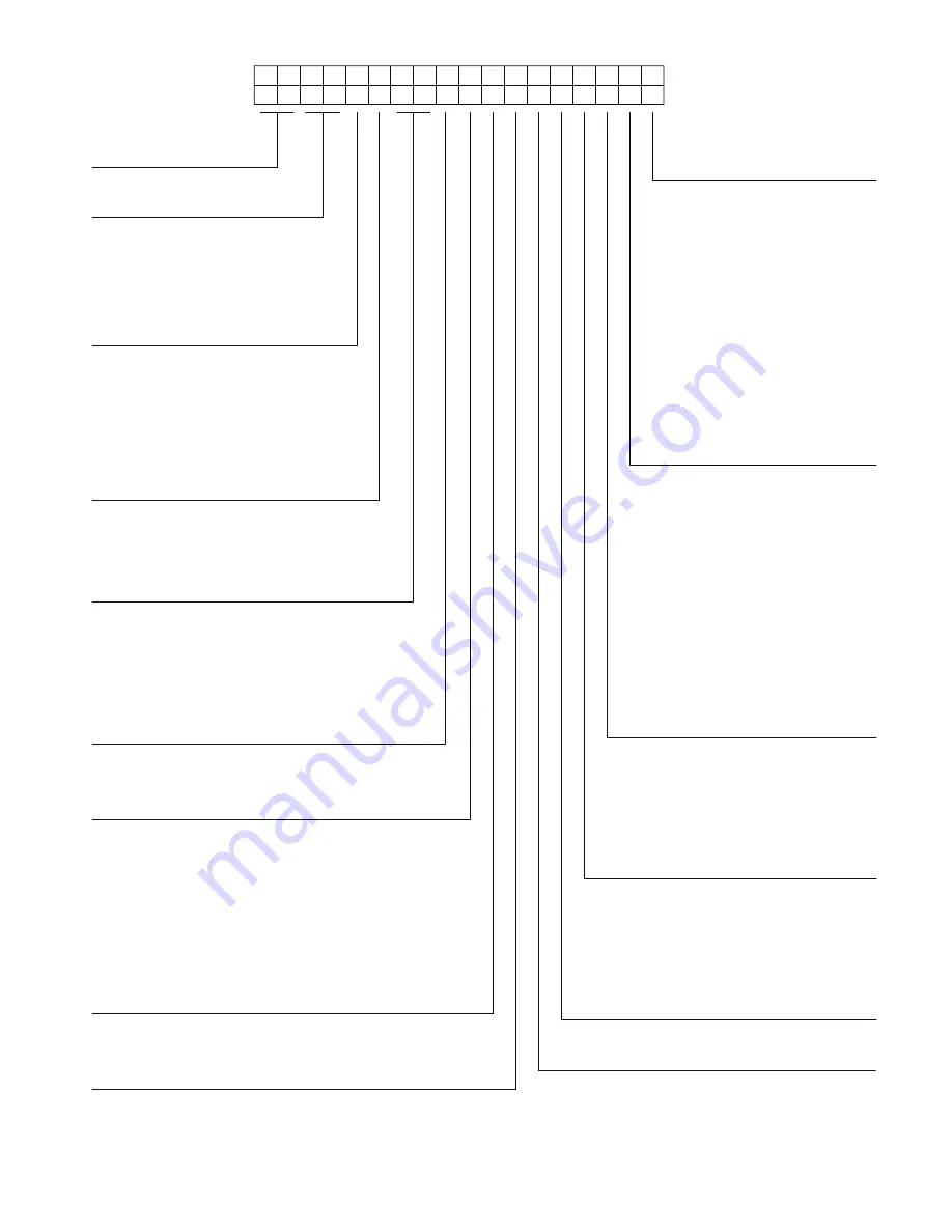
Fig. 1 —  48HC 07-12 Model Number Nomenclature (Example)

4

8

H

C

D

E

0

9

A

2

A

6

A

0

A

3

B

0

1

2

3

4

5

6

7

8

9

10

11

12

13

14

15

16

17

18

Model Series - WeatherMaster

®

HC - High Efficiency

Unit Heat Type

48 - Gas Heat Packaged Rooftop

Cooling Tons

07 -  6 ton
08 -  7.5 ton
09 -  8.5 ton
11 -  10 ton (12.0 EER)
12 -  10 ton (11.5 EER)

Heat Options

D  =  Low Gas Heat
E  =  Medium Gas Heat
F  =  High Gas Heat
S  =  Low Heat w/ Stainless Steel Exchanger
R  =  Medium Heat w/ Stainless Steel Exchanger
T  =  High Heat w/ Stainless Steel Exchanger
(Low NO

x

 models include – Stainless Steel HX)     

Sensor Options

A =  None
B  =  RA Smoke Detector
C  =  SA Smoke Detector
D  =  RA + SA Smoke Detector
E =  CO

2

F  =  RA Smoke Detector and CO

2

G =  SA Smoke Detector and CO

2

H  =  RA + SA Smoke Detector and CO

2

Indoor Fan Options

1  =  Standard Static Option - Belt Drive
2  =  Medium Static Option - Belt Drive
3  =  High Static Option - Belt Drive

Refrig. Systems Options

A  =  Single stage cooling models
B  =  Single stage cooling models
   with 

Humidi-MiZer

®

D  =  Two stage cooling models
E  =  Two stage cooling models with Humidi-MiZer
F  =  Single stage cooling models with
   

MotorMaster Low Ambient Controller

G =  Two stage cooling models with
   

MotorMaster Low Ambient Controller

Coil Options (RTPF) (Outdoor - Indoor - Hail Guard)

A  =  Al/Cu - Al/Cu
B  =  Precoat Al/Cu - Al/Cu
C  =  E-coat Al/Cu - Al/Cu
D  =  E-coat Al/Cu - E-coat Al/Cu
E  =  Cu/Cu - Al/Cu
F  =  Cu/Cu - Cu/Cu
M =  Al/Cu -Al/Cu — Louvered Hail Guard
N  =  Precoat Al/Cu - Al/Cu — Louvered Hail Guard
P  =  E-coat Al/Cu - Al/Cu — Louvered Hail Guard
Q =  E-coat Al/Cu - E-coat Al/Cu — Louvered Hail Guard
R  =  Cu/Cu - Al/Cu — Louvered Hail Guard
S  =  Cu/Cu - Cu/Cu — Louvered Hail Guard

Voltage

1 =  575/3/60
5 =  208-230/3/60
6 =  460/3/60

Design Revision

A  =  Factory Design Revision 

Base Unit Controls

0  =  Electromechanical Controls can be used with W7212
   

EconoMi$er (Non-Fault Detection and Diagnostic)

1 =  PremierLink

TM

 Controller

2  =  RTU Open Multi-Protocol Controller
6  =  Electro-mechanical w/ 2-speed fan and W7220
   

Econo controller controls. Can be used with W7220


EconoMi$er X (w/ Fault Detection & Diagnostic)

D =  ComfortLink Controls

Intake / Exhaust Options

A =  None
B  =  Temperature Economizer w/ Barometric Relief
F  =  Enthalpy Economizer w/ Barometric Relief
K =  2-Position Damper
U  =  Low Leak Temperature Economizer
   

w/ Barometric Relief

W =  Low Leak Enthalpy Economizer 
   

w/ Barometric Relief

Service Options

0 =  None
1  =  Unpowered Convenience Outlet
2  =  Powered Convenience Outlet
3 =  Hinged Panels
4  =  Hinged Panels and
   

Unpowered Convenience Outlet

5  =  Hinged Panels and
   

Powered Convenience Outlet

C  =   Foil Faced Insulation
D  =  Foil Faced Insulation with
   

Unpowered Convenience Outlet

E  =  Foil Faced Insulation with
   

Powered Convenience Outlet

F  =  Foil Faced Insulation & Hinged Panels
G =  Foil Faced Insulation & Hinged Panels
   

with Unpowered Convenience Outlet

H  =  Foil Faced Insulation & Hinged Panels
   

with Powered Convenience Outlet

Factory Assigned

0 =  Standard
1 =  LTL

Electrical Options 

A = None
B = HACR Breaker
C =  Non-Fused Disconnect
D =  Thru-The-Base Connections
E  =  HACR and Thru-The Base Connections
F  =  Non-Fused Disconnect and
  Thru-The-Base 

Connections

G  =  2-Speed Indoor Fan (VFD) Controller
H  =  2-Speed Fan Controller (VFD) and
  HACR 

Breaker 

J  =  2-Speed Fan Controller (VFD) and 
  Non-Fused 

Disconnect

K  =  2-Speed Fan Controller (VFD) and 
  Thru-The-Base 

Connections

L  =  2-Speed Fan Controller (VFD) w/ HACR
    Breaker and Thru-The Base Connections
M =  2-Speed Fan Controller (VFD) with 
    Non-Fused Disconnect and 
  Thru-The-Base 

Connections

Example:

Position:

Summary of Contents for WeatherMaster 48HC07 Series

Page 1: ... ComfortLink Control Factory Option 50 PremierLink Controller Factory Option 50 RTU Open Controller 50 Controller Options 50 LOW AMBIENT CONTROL FACTORY OPTION Step 13 Adjust Factory Installed Options 51 SMOKE DETECTORS ECONOMI ER IV OCCUPANCY SWITCH Step 14 Install Accessories 51 Step 15 Check Belt Tension 51 Pre Start and Start Up 52 START UP CHECKLIST CL 1 SAFETY CONSIDERATIONS Improper install...

Page 2: ...az Si le fournisseur de gaz n est pas accessible appeler le service d incendie L installation et l entretien doivent être effectués par un installateur ou une entreprise d entretien qualifié ou le fournisseur de gaz WARNING CARBON MONOXIDE POISONING HAZARD Failure to follow instructions could result in severe personal injury or death due to carbon monoxide poisoning if com bustion products infiltr...

Page 3: ...r or final unit disposal Wear safety glasses and gloves when handling refrigerants Keep torches and other ignition sources away from refriger ants and oils WARNING CUT HAZARD Failure to follow this caution may result in personal injury Sheet metal parts may have sharp edges or burrs Use care and wear appropriate protective clothing safety glasses and gloves when handling parts and servicing air co...

Page 4: ...Table 1 Rated Indoor Airflow Pre Installation Complete the following checks before installation 1 Consult local building codes and the NEC National Elec trical Code ANSI NFPA 70 for special installation requirements 2 Determine unit location from project plans or select unit location Check for possible overhead obstructions which may interfere with unit lifting or rigging MODEL NUMBER RATED INDOOR...

Page 5: ... 5 208 230 3 60 6 460 3 60 Design Revision A Factory Design Revision Base Unit Controls 0 Electromechanical Controls can be used with W7212 EconoMi er Non Fault Detection and Diagnostic 1 PremierLinkTM Controller 2 RTU Open Multi Protocol Controller 6 Electro mechanical w 2 speed fan and W7220 Econo controller controls Can be used with W7220 EconoMi er X w Fault Detection Diagnostic D ComfortLink ...

Page 6: ...6 Fig 2 Unit Dimensional Drawing Sizes 07 09 ...

Page 7: ...7 Fig 2 Unit Dimensional Drawing Sizes 07 09 cont ...

Page 8: ...8 Fig 3 Unit Dimensional Drawing Sizes 11 and 12 ...

Page 9: ...9 Fig 3 Unit Dimensional Drawing Sizes 11 and 12 cont ...

Page 10: ...stall unit in an indoor location Do not locate air inlets near exhaust vents or other sources of contaminated air For proper unit operation adequate combustion and ventilation air must be provided in accordance with Section 5 3 Air for Com bustion and Ventilation of the National Fuel Gas Code ANSI Z223 1 American National Standards Institute and NFPA National Fire Protection Association 54 TIA 54 ...

Page 11: ...t supports 2 Check and tighten the bottom condensate drain connection plug 3 Rig and place unit 4 Convert unit to side duct connection arrangement 5 Install field fabricated ductwork at unit duct openings 6 Install outdoor air hood 7 Install flue hood 8 Install gas piping 9 Install condensate line trap and piping 10 Make electrical connections 11 Install other accessories FRAME MOUNTED INSTALLATIO...

Page 12: ...RT WITHOUT THE WRITTEN AUTHORIZATION OF CARRIER CORPORATION 1 DEC 2 DEC 3 DEC ANG MATERIAL AUTHORIZATION NUMBER TITLE 1029120 CURB ASY ROOF ENGINEERING MANUFACTURING ENGINEERING REQUIREMENTS SIZE DRAWING NUMBER REV T 005 Y 002 DRAFTER CHECKER D 50HJ405012 C WEIGHT MMC 12 16 09 SHEET 5 OF 5 SURFACE FINISH MFG PURCH MODEL INTERNAL USE ONLY NEXT DRAWING SCALE DISTRIBUTION PURCH N A NOTES 1 ROOFCURB A...

Page 13: ... of duct length from the unit basepan Insulate and weatherproof all external ductwork joints and roof openings with counter flashing and mastic in accordance with applicable codes Ducts passing through unconditioned spaces must be insulated and covered with a vapor barrier If a plenum return is used on a vertical unit the return should be ducted through the roof deck to comply with applicable fire...

Page 14: ...s with counter flashing and mastic in accor dance with applicable codes Do not cover or obscure visibility to the unit s informative data plate when insulating horizontal ductwork NOTES 1 SPREADER BARS REQUIRED Top damage will occur if spreader bars are not used 2 Dimensions in are in millimeters 3 Hook rigging shackles through holes in base rail as shown in detail A Holes in base rails are center...

Page 15: ... used as the hood top while the hood sides divider and filter are packaged together attached to a metal support tray using plastic stretch wrap and shipped in the return air compart ment behind the indoor coil access panel The hood assem bly s metal tray is attached to the basepan and also attached to the damper using two plastic tie wraps 2 To gain access to the hood remove the filter access pane...

Page 16: ... the joint between the unit top panel and the hood top 7 Replace the filter access panel Fig 12 Typical Access Panel Locations Fig 13 Economizer and Two Position Damper Hood Parts Location Fig 14 Indoor Coil Access Panel Relocation Fig 15 Economizer Hood Construction Fig 16 Economizer Filter Installation FILTER ACCESS PANEL INDOOR COIL ACCESS PANEL HOOD PARTS PLASTIC TIE WRAP QTY 2 SCREWS FORMETAL...

Page 17: ...ame characteristics See Tables 5 and 6 Table 5 Natural Gas Manifold Pressure Ranges NOTE LOW FIRE 1 7 in wg 423 Pa applies to the following units only 48HCD E F 07 48HCD 08 and 48HCD 09 Manifold pressure for LP fuel use must be adjusted to specified range Follow instructions in the accessory kit to make initial readjustment Table 6 Liquid Propane Manifold Pressure Ranges NOTE LOW FIRE 5 0 in wg 14...

Page 18: ...o be required to convert gas pressure from pounds to inches of pressure The manual shutoff valve must be located within 6 ft 1 83 m of the unit The union located in the final leg entering the unit must be located at least 9 in 230 mm away from the access panel to permit the panel to be removed for service If a regulator valve is installed it must be located a minimum of 4 ft 1220 mm away from the ...

Page 19: ... ground joint union Check for gas leaks at the field installed and factory installed gas lines after all piping connections have been completed Use soap and water solution or method specified by local codes and or regulations NOTE If orifice hole appears damaged or it is suspected to have been re drilled check orifice hole with a numbered drill bit of cor rect size Never re drill an orifice A burr...

Page 20: ...it breaker Max wire size is 4 AWG copper only per pole on contactors and 2ga AWG copper only per pole on optional non fused disconnect or HACR cir cuit breaker See Fig 27 and the unit label diagram for field power wiring connections NOTE TEST LEADS Unit may be equipped with short leads pigtails on the field line connection points on contactor C or optional disconnect switch These leads are for fac...

Page 21: ...o the OFF position with red arrow point ing at OFF 9 Install the handle on to the painted cover horizontally with the red arrow pointing to the left 10 Secure the handle to the painted cover with 2 screws and lock washers supplied 11 Engaging the shaft into the handle socket re install 3 hex screws on the NFD enclosure 12 Re install the unit front panel Fig 30 Handle and Shaft Assembly for NFD Fig...

Page 22: ...s during operation must be within voltage range indicated on unit nameplate On 3 phase units voltages between phases must be balanced within 2 and the current within 10 Use the formula shown below to determine the percent of voltage imbalance Operation on im proper line voltage or excessive phase imbalance constitutes abuse and may cause damage to electrical components Such operation would invalid...

Page 23: ...ol box access panel See Fig 33 The primary leads to the convenience outlet transformer are not factory connected Selection of primary power source is a customer option If local codes permit the transformer primary leads can be connected at the line side terminals on the unit mounted non fused disconnect or HACR breaker switch this will provide service power to the unit when the unit disconnect swi...

Page 24: ...ig 27 FIELD CONTROL WIRING The 48HC unit requires an external temperature control device This device can be a thermostat field supplied or a Premier Link controller available as factory installed option or as field installed accessory for use on a Carrier Comfort Net work or as a stand alone control or the RTU Open Controller for Building Management Systems using non CCN protocols RTU Open control...

Page 25: ... on the left side of the control box The raceway provides the UL required clearance between high voltage and low voltage wiring 3 Use wire nuts to connect humidistat cable to the leads in the low voltage wiring as shown in Fig 41 connecting PNK to PNK and PNK BLK to PNK BLK To connect the Thermidistat device 33CS2PPRH 01 1 Route the Thermidistat multi conductor thermostat cable field supplied thro...

Page 26: ...26 Fig 41 Typical Humidi MiZer Adaptive Dehumidification System Humidistat Wiring ...

Page 27: ...midification System with Edge Pro Thermidistat Device TYPICAL CONTROL WIRING DIAGRAMS See Fig 43 50 Rc Rh W1 G Y2 C O W2 B Y1 OAT RRS SRTN HUM D1 D2 V Vg X C G W2 W1 Y2 Y1 R Edge Programable Thermostat Unit CTB THERMOSTAT Connection not required Humidi MiZer FIOP ...

Page 28: ...28 Fig 43 Electro Mechanical Control Wiring Diagram ...

Page 29: ...29 Fig 44 Electro Mechanical Control Wiring Diagram with Humidi MiZer System ...

Page 30: ...30 Fig 45 Typical ComfortLink Control Wiring Diagram 48HC 08 09 shown ...

Page 31: ...31 Fig 46 Typical 48HC ComfortLink Control Power Wiring Diagram with Optional Humidi MiZer System 208 230V 460V 3 Ph 60 Hz shown ...

Page 32: ...32 Fig 47 Typical PremierLink Control Wiring Diagram ...

Page 33: ...33 Fig 48 Typical PremierLink Control Wiring Diagram with Humidi MiZer System Option ...

Page 34: ...34 Fig 49 Typical RTU Open Controller Wiring Diagram ...

Page 35: ...35 Fig 50 Typical RTU Open Controller Wiring Diagram with Humidi MiZer System Option ...

Page 36: ... other options are available with bus sensors User Interface The interface provides status for normal operation setup pa rameters checkout tests and alarm and error conditions with a 2 line 16 character LCD display and four button keypad Electrical Rated Voltage 20 to 30 Vac RMS 50 60 Hz Transformer 100 va maximum system input Nominal Power Consumption at 24 Vac 60 Hz 11 5 VA without sensors or ac...

Page 37: ...tion OAT OAT 20k NTC and COM Outdoor Air Temperature Sensor Polarity Insensitive Connection S BUS S BUS S BUS Sylk Bus Enthalpy Control Sensor Polarity Insensitive Connection Bottom Left Terminal Block IAQ 2 10 2 10 VDC Air Quality Sensor Input e g CO2 sensor IAQ COM COM Air Quality Sensor Common IAQ 24V 24 VAC Air Quality Sensor 24 VAC Source ACT 2 10 2 10 VDC Damper Actuator Output 2 10 VDC ACT ...

Page 38: ... Fig 54 for CO2 sensor wiring Fig 54 CO2 Sensor Wiring Interface Overview This section describes how to use the Economizer s user inter face for Keypad and menu navigation Settings and parameter changes Menu structure and selection User Interface The user interface consists of a 2 line LCD display and a 4 but ton keypad on the front of the economizer controller Keypad Use the four navigation butto...

Page 39: ...tters MA or MAT indicating a mixed air temperature sensor location before the cooling coil This unit application has the control sensor locat ed after the cooling coil in the fan section where it is designated as Cooling Supply Air Temperature or SAT sensor Setup and Configuration Before being placed into service the W7220 Economizer mod ule must be set up and configured for the installed system T...

Page 40: ...f measured mixed air from MAT sensor Displays _ _ _ F if not connected short or out of range DA TEMP _ _ _ F 0 to 140 F DISCHARGE AIR TEMPERATURE after Heating section Displays when Discharge Air sensor is connected and displays mea sured discharge temperature Displays _ _ _F if sensor sends invalid value if not connected short or out of range OA TEMP _ _ _ F 40 to 140 F OUTSIDE AIR TEMP Displays ...

Page 41: ...is NOT connected VENTMAX With 2 speed fan units VENTMAX L low speed fan and VENTMAX H high speed fan settings are required 2 8 V 2 to 10 Vdc DCV MAXIMUM DAMPER POSITION Displays only if a CO2 sensor is connected Used for Vbz ventilation max cfm setpoint Displays 2 to 10 V if 3 sensors RA OA and MA In AUTO mode dampers controlled by CFM 100 to 9990 cfm increment by 10 If OA MA RA and CO2 sensors ar...

Page 42: ...tory defaults when set to YES LCD will briefly flash YES and change to NO but all parameters will change to the factory default values NOTE RECHECK AUX2 IN and FANTYPE for required 2 speed values ADVANCED SETUP MA LO SET 45 F 35 to 55 F Incremented by 10 SUPPLY AIR TEMPERATURE LOW LIMIT Temperature to achieve Freeze Protection close damper and alarm if tem perature falls below setup value FREEZE P...

Page 43: ... or signals an ERV that the conditions are not good for economizing but are for ERV operation SYS 24 Vac out Issues a system alarm CONNECT EXH1 N A N A Closes the power exhaust fan 2 relay EXH1 ALARMS Alarms display only when they are active The menu title ALARMS includes the number of active alarms in parenthesis When using SYLK bus sensors SYLK will appear on the screen and when using 20k OA tem...

Page 44: ... see Tables 13 and 14 For en thalpy operation with a 1 speed indoor fan with or without DCV see Tables 15 and 16 For dry bulb operation with a 2 speed indoor fan with or without DCV see Tables 17 and 18 For enthalpy operation with a 2 speed indoor fan with or with out DCV see Tables 19 and 20 Table 12 Damper Minimum Position Settings and Readings on Checkout Menu MENU PARAMETER PARAMETER DEFAULT V...

Page 45: ... HIGH 24v On 0v Off MIN POS to Full Open Closed to Full Open DEMAND CONTROLLED VENTILATION DCV OUTSIDE AIR GOOD TO ECONOMIZE Y1 I Y2 I FAN SPEED Y1 O Y2 O OCCUPIED UNOCCUPIED Below CO2 Set No OFF OFF HIGH 0v Off 0v Off VENTMIN Closed ON OFF HIGH 24v On 0v Off VENTMIN Closed ON ON HIGH 24v On 24v On VENTMIN Closed Yes OFF OFF HIGH 0v Off 0v Off VENTMIN Closed ON OFF HIGH 0v Off 0v Off VENTMIN to Fu...

Page 46: ... 0v Off 0v Off VENTMIN Closed ON OFF HIGH 0v Off 0v Off VENTMIN to Full Open Closed to Full Open ON ON HIGH 24v On 0v Off VENTMIN to Full Open Closed to Full Open Above CO2 Set No OFF OFF HIGH 0v Off 0v Off VENTMIN to VENTMAX Closed ON OFF HIGH 24v On 0v Off VENTMIN to VENTMAX Closed ON ON HIGH 24v On 24v On VENTMIN to VENTMAX Closed Yes OFF OFF HIGH 0v Off 0v Off VENTMIN to VENTMAX Closed ON OFF ...

Page 47: ...Closed ON ON HIGH 24v On 24v On VENTMIN to VENTMAX Closed Yes OFF OFF LOW 0v Off 0v Off VENTMIN to VENTMAX Closed ON OFF LOW 0v Off 0v Off VENTMIN to Full Open Closed to Full Open ON ON HIGH 24v On 0v Off VENTMIN to Full Open Closed to Full Open DEMAND CONTROLLED VENTILATION DCV OUTSIDE AIR GOOD TO ECONOMIZE Y1 I Y2 I FAN SPEED Y1 O Y2 O OCCUPIED UNOCCUPIED NO CO2 SENSOR NO OFF OFF LOW 0v Off 0v O...

Page 48: ...olled by the W7220 but it re quires the status to know where to position the OA damper for minimum position for the fan speed The 2 speed fan delay is available when the system is pro grammed for 2 speed fan in the System Setup menu item The 2 speed fan delay is defaulted to 5 minutes and can be changed in the Advanced Setup menu item When the unit has a call for Y1 In and in the free cooling mode...

Page 49: ...sired alarm 2 Press the Enter button ERASE displays 3 Press the Enter button ALARM ERASED displays 4 Press the Menu Up Exit button to complete the action and return to the previous menu NOTE If the alarm still exists after clearing it it is redisplayed within 5 seconds Smoke Detectors Smoke detectors are available as factory installed options on 48HC models Smoke detectors may be specified for Sup...

Page 50: ...Rooftop Unit with ComfortLink Controls PremierLink Controller Factory Option For details on operating 48HC units equipped with the factory installed PremierLink controller option refer to the Premier Link Retrofit Rooftop Controller Version 3 x Installation Start Up and Configuration instructions manual RTU Open Controller For details on operating 48HC units equipped with the factory installed RTU...

Page 51: ... guard Motormaster head pressure controls Phase monitor control Energy Recovery Ventilator ERV Refer to separate installation instructions for information on in stalling these accessories Step 15 Check Belt Tension Measure the belt span length as shown in Fig 60 Calculate the required deflection by multiplying the belt span length by 1 64 For example if the belt span length is 32 inches 32 x 1 64 ...

Page 52: ...art Up instructions Download the latest versions from HVAC Part ners www hvacpartners com Table 1 Table 2 BELT CROSS SECTION SMALLEST SHEAVE DIAMETER BELT DEFLECTION FORCE LBS UNNOTCHED BELTS NOTCHED BELTS USED NEW USED NEW A AX 3 0 3 6 3 7 5 5 4 1 6 1 3 8 4 8 4 5 6 8 5 0 7 4 5 0 7 0 5 4 8 0 5 7 8 4 B BX 3 4 4 2 4 9 7 2 4 4 5 6 5 3 7 9 7 1 10 5 5 8 8 6 6 3 9 4 8 5 12 6 BELT CONDITION TENSION FORCE...

Page 53: ......

Page 54: ...to discontinue or change at any time specifications or designs without notice and without incurring obligations Catalog No 04 53480221 01 Printed in U S A Form 48HC 7 12 06SI Pg 54 1 19 Replaces 48HC 7 12 05SI Carrier Corporation 2019 ...

Page 55: ...for leaks Y N _____ Check that indoor air filters are clean and in place Y N _____ Check that outdoor air inlet screens are in place Y N _____ Verify that unit is level Y N _____ Check fan wheels and propeller for location in housing orifice and verify setscrew is tight Y N _____ Verify that fan sheaves are aligned and belts are properly tensioned Y N _____ Verify that scroll compressors are rotat...

Page 56: ...cooling Close Y1 Y N _____ OBSERVE AND RECORD A Suction pressure _______________ PSIG B Discharge pressure _______________ PSIG C Entering air temperature _______________ F D Liquid line temperature at outlet or reheat coil _______________ F E Confirm correct rotation for compressor Y N _____ F Check for correct ramp up of outdoor fan motor as condenser coil warms Y N _____ 4 Check unit charge per...

Reviews: