


32
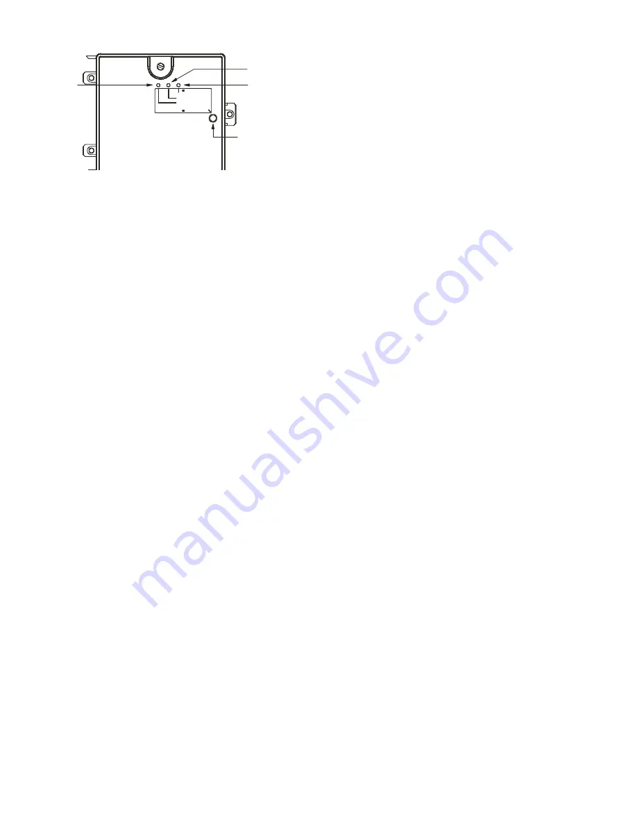
Fig. 49 — Controller Assembly
NOTE: All trouble states are locked by the duct smoke detector.
The trouble condition must be cleared and then the duct smoke de-
tector must be reset in order to restore it to the normal state.
RESETTING ALARM AND TROUBLE CONDITION TRIPS
Manual reset is required to restore smoke detector systems to
Normal operation. For installations using two sensors, the duct
smoke detector does not differentiate which sensor signals an
alarm or trouble condition. Check each sensor for Alarm or
Trouble status (indicated by LED). Clear the condition that has
generated the trip at this sensor. Then reset the sensor by press-
ing and holding the reset button (on the side) for 2 seconds.
Verify that the sensor’s Alarm and Trouble LEDs are now off.
At the controller, clear its Alarm or Trouble state by pressing
and holding the manual reset button (on the front cover) for
2 seconds. Verify that the controller’s Alarm and Trouble
LEDs are now off. Replace all panels.
TROUBLESHOOTING
Controller’s Trouble LED is On:
1. Check the Trouble LED on each sensor connected to the
controller. If a sensor’s Trouble LED is on, determine the
cause and make the necessary repairs.
2. Check the wiring between the sensor and the controller. If
wiring is loose or missing, repair or replace as required.
Controller’s Trouble LED is Flashing:
1. One or both of the sensors is 100% dirty.
2. Determine which Dirty LED is flashing, then clean that sen-
sor assembly as described in the detector cleaning section.
Sensor’s Trouble LED is On:
1. Check the sensor’s Dirty LED. If it is flashing, the sensor
is dirty and must be cleaned.
2. Check the sensor’s cover. If it is loose or missing, secure
the cover to the sensor housing.
3. Replace sensor assembly.
Sensor’s Power LED is Off:
1. Check the controller’s Power LED. If it is off, determine
why the controller does not have power and make the nec-
essary repairs.
2. Check the wiring between the sensor and the controller. If
wiring is loose or missing, repair or replace as required.
Controller’s Power LED is Off:
1. Ensure the circuit supplying power to the controller is
operational. If not, make sure JP2 and JP3 are set correctly
on the controller before applying power.
2. Verify that power is applied to the controller’s supply
input terminals. If power is not present, replace or repair
wiring as required.
Remote Test/Reset Station’s Trouble LED Does Not Flash
When Performing a Dirty Test, But the Controller’s Trouble
LED Does:
1. Verify that the remote test/station is wired as shown in
Fig. 47. Repair or replace loose or missing wiring.
2. Configure the sensor dirty test to activate the controller’s
supervision relay. See “To Configure the Dirty Sensor Test
Operation” for details.
Sensor’s Trouble LED is On, But the Controller’s Trouble
LED is OFF:
Remove JP1 on the controller.
Supply Air Temperature (SAT) Sensor
On FIOP-equipped 50KCQ unit, the unit is supplied with a
supply-air temperature (SAT) sensor (part number:33ZCSEN-
SAT). This sensor is a tubular probe type, approx 6-in.
(12.7 mm) in length. It is a nominal 10-k ohm thermistor. See
PremierLink Installation, Start-Up and Configuration Instruc-
tions
for temperature-resistance characteristic.
PREMIERLINK CONTROL
For details on operating 50KCQ units equipped with the facto-
ry-installed PremierLink controller option, refer to the
Pre-
mierLink Retrofit Rooftop Controller Version 3.x Installation,
Start-Up, and Configuration Instructions
manual.
RTU-OPEN CONTROL SYSTEM
For details on operating 50KCQ units equipped with the facto-
ry-installed RTU Open controller, refer to the
“Factory-In-
stalled RTU Open Multi-Protocol Controller Control, Start-
Up, Operation and Troubleshooting”
manual.
ALARM
POWER
TEST/RESET
SWITCH
TROUBLE
RESET
ALARM
TROUBLE
POWER
Summary of Contents for WeatherMaker 50KCQ A04 Series
Page 34: ...34 Fig 53 RTU Open Overlay for Economizer Wiring ...
Page 35: ...35 Fig 54 VFD Overlay for W2770 Controller Wiring ...
Page 70: ...70 Fig C 50KCQ A04 A05 A06 Control Wiring Diagram 575 3 60 APPENDIX D WIRING DIAGRAMS ...
Page 71: ...71 Fig D 50KCQ A04 A05 A06 Power Wiring Diagram 208 230 1 60 APPENDIX D WIRING DIAGRAMS ...
Page 72: ...72 Fig E 50KCQ A04 A05 A06 Power Wiring Diagram 208 230 3 60 APPENDIX D WIRING DIAGRAMS ...
Page 73: ...73 Fig F 50KCQ A04 A05 A06 Power Wiring Diagram 460 3 60 APPENDIX D WIRING DIAGRAMS ...
Page 74: ...74 Fig G 50KCQ A04 A05 A06 Power Wiring Diagram 575 3 60 APPENDIX D WIRING DIAGRAMS ...
Page 75: ...75 Fig H 50KCQ Premier Link Control Diagram APPENDIX D WIRING DIAGRAMS ...
Page 76: ...76 Fig I 50KCQ RTU Open Control Diagram APPENDIX D WIRING DIAGRAMS ...


