


73
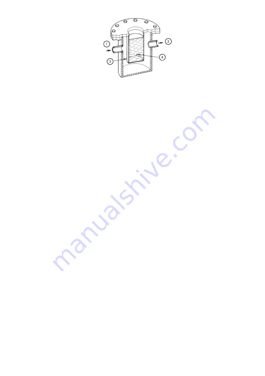
1: From system
2: To vacuum pump
3: Moisture condenses on cold surfaces
4: Mixture of dry ice and methyl alcohol
Fig 41
– dehydration cold trap
Perform dehydration as follows:
1. Connect a high capacity vacuum pump (0.002 m3/s or larger is recommended) to the refrigerant vacuum/
charging valve. Tubing from the pump to the chiller should be as short in length with a minimum diameter of 13
mm and as large in diameter as possible to provide least resistance to gas flow.
2. Use an absolute pressure manometer or a electronic micron gage to measure the vacuum. Open the shutoff
valve to the vacuum indicator only when taking a reading. Leave the valve open for 3 minutes to allow the
indicator vacuum to equalize with the chiller vacuum.
3. If the entire chiller is to be dehydrated, open all isolation valves (if present).
4. With the chiller ambient temperature at 15.6°C or higher, operate the vacuum pump until the manometer reads
757 mm Hg (vac), (-100.9 kPag), or a vacuum indicator reads 1.7°C. Operate the pump an additional 2 hours. Do
not apply a greater vacuum than 100.1 kPa (757 mm Hg) or go below 0.56°C on the wet bulb vacuum indicator.
At this temperature and pressure, isolated pockets of moisture can turn into ice. The slow rate of evaporation
(sublimation) of ice at these low temperatures and pressures greatly increases dehydration time.
5. Valve off the vacuum pump, stop the pump, and record the instrument reading.
6. After a 2-hour wait, take another instrument reading. If the reading has not changed, dehydration is complete. If
the reading indicates vacuum loss, repeat Steps 4 and 5.
7. If the reading continues to change after several attempts, perform a leak test (maximum 310 kPa pressure).
Locate and repair the leak, and repeat dehydration.
8. Once dehydration is complete, the evacuation process can continue. The final vacuum prior to charging the unit
with refrigerant should in all cases be 0.3 kPa [abs] or less.
5.1.9- Inspect water piping
Refer to piping diagrams provided in the certified drawings, Inspect the piping to the cooler and condenser. Be
sure that flow directions are correct and that all piping specifications have been met. Check the tightening of
waterboxes mounting. Check if
there’s no water leak between tube-sheet and waterbox. Do not introduce any
significant static or dynamic pressure into the heat exchange circuit (with regard to the design operating
pressures).
Before any start-up verify that the heat exchange fluid is compatible with the materials and the water circuit
coating. In case additives or other fluids than those recommended by Carrier are used, ensure that the fluids are
not considered as a gas, and that they belong to class 2, as defined in directive 97/23/EC.
Carrier recommendations on heat exchange fluids:
• No NH4+ ammonium ions in the water, they are very detrimental for copper. This is one of the most important
factors for the operating life of copper piping. A content of several tenths of mg/l will badly corrode the copper over
time.
• Cl- Chloride ions are detrimental for copper with a risk of perforations by corrosion by puncture. If possible
keep below 10 mg/l.
• SO4 2- sulphate ions can cause perforating corrosion, if their content is above 30 mg/l.
No fluoride ions (<0.1 mg/l).
• No Fe2+ and Fe3+ ions with non negligible levels of dissolved oxygen must be present. Dissolved iron < 5 mg/l
with dissolved oxygen < 5 mg/l.
• Dissolved silica: Silica is an acid element of water and can also lead to corrosion risks. Content < 1mg/l.
Summary of Contents for PIC 5+
Page 26: ...26 VFD not shown Fig 13 Sensors actuators location ...
Page 52: ...52 Fig 24 19DV control box ...
Page 53: ...53 1 Power supply 24V AC 2 LEN 3 CCN 4 Ethernet 5 USB Fig 25 19DV HMI box rear view ...
Page 54: ...54 Fig 26 19DV IOB1 wiring Fig 27 19DV IOB2 wiring ...
Page 57: ...57 ...
Page 113: ...113 APPENDIX A SmartView SCREEN AND MENU STRUCTURE ...
Page 114: ...114 Detailed menu description ...
Page 116: ...116 APPENDIX B MAINTENANCE SUMMARY AND LOGSHEETS Cont 19DV monthly Maintenance Log ...


