background image

13

Configure Basic Unit  — 

The user must be logged on

as Admin to adjust these control configurations.

1. From the HOME menu, select the press the [CONFIG]

softkey to enter the CONFIGURATION menu.

2. From the CONFIGURATION menu, press the [FACTO-

RY] softkey to enter the FACTORY CONFIGURATION

menu.

3. Use arrow keys to scroll around the screen and select the

data field to change. These buttons scroll through the data

fields, as well as up and down the screen.

4. To change a field, move the cursor brackets to the desired

field then press <ENTER>.

5. If the wrong field is entered or you do not want to change

a value, press [CANCEL] to leave the current setting in-

tact.

See Table 4 for a description of the items on the FACTORY

CONFIGURATION menu.

Table 4 — Factory Configuration Menu

*These points are factory set to the appropriate value if affected by a factory-
installed option.

Unit Configuration — 

 The user must be logged on as

Admin or User to adjust these configuration points.

1. From the HOME menu, select the press the [CONFIG]

softkey to enter the CONFIGURATION menu.

2. From the CONFIGURATION menu, press the [UNIT]

softkey to enter the second CONFIGURATION menu.

3. Use arrow keys to scroll around the screen and select the

data field to change. These buttons scroll through the data

fields, as well as up and down the screen.

4. To change a field, move the cursor brackets to the desired

field then press <ENTER>.

5. If the wrong field is entered, do not change a value, press

[CANCEL] to leave the current setting intact.

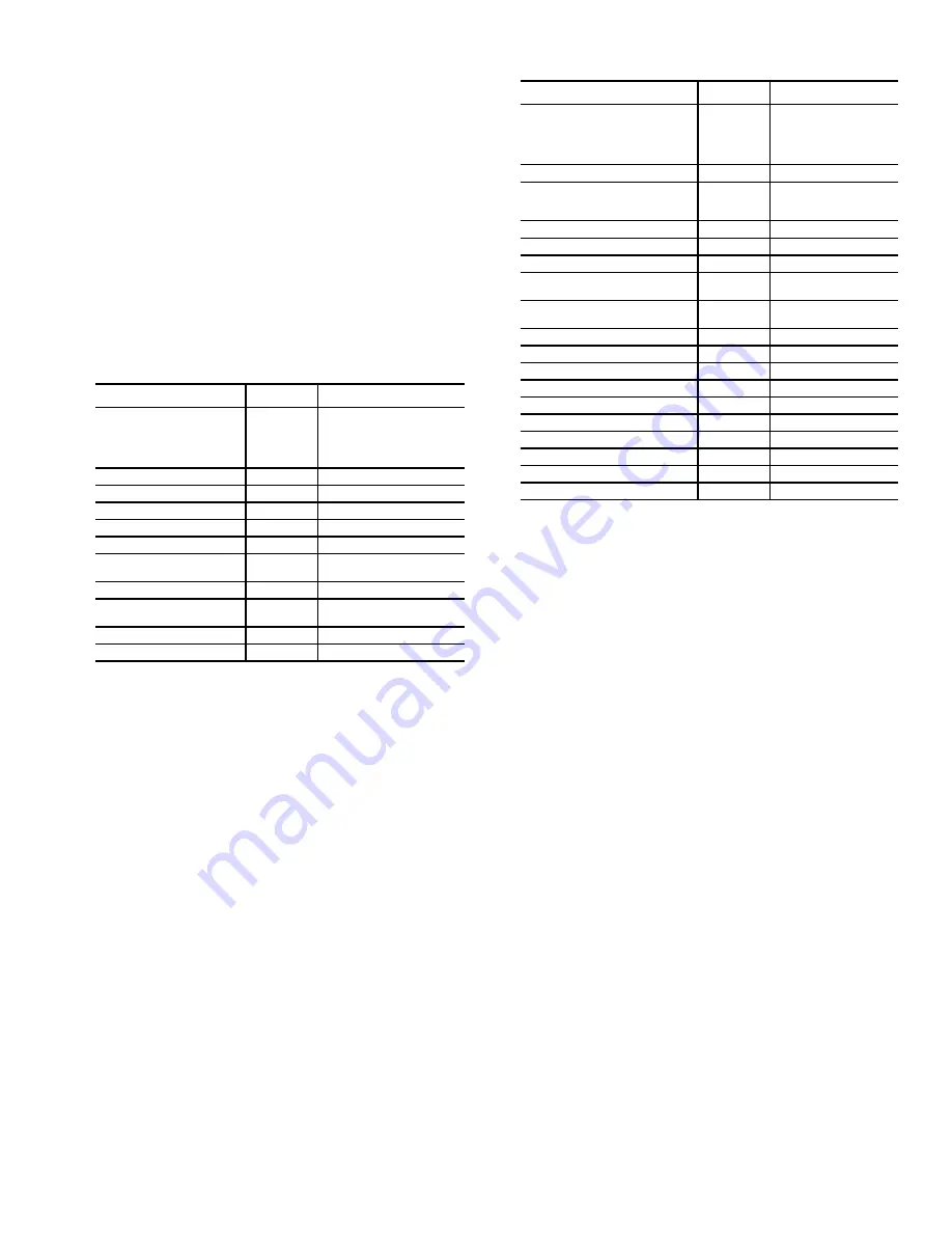
See Table 5 for a description of the items on the CONFIGU-

RATION menu.

Table 5 — Configuration Menu

*These points are factory set to the appropriate value if affected by a factory-
installed option.

Unit Status — 

  The system status can be monitored with-

out logging onto the BACview display by pressing the [Status]

softkey on the HOME menu and using the arrow keys to navi-

gate the screen.

See Table 6 for a description of the items on the on the

UNIT STATUS menu.

Display / Set Runtime Alarms — 

 It is not necessary

to log onto the BACview display to view the compressor and

fan run time values. It is necessary to log onto BACview to set

runtime limits or clear the accumulated run times.

To view run times, press the [CONFIG] softkey on the

HOME menu, then select the RUNTIME option from the

CONFIGURATION menu. Use the arrow keys to scroll

through the display.

To change runtime alarm values move to the column

marked "Alarm" and press <ENTER> then use the numeric

keys to enter the alarm value and again press <ENTER>. To re-

set the accumulated run time, move to the column marked

"Clear", press <ENTER>, then the [INCR] softkey to select

"Yes", then press <ENTER>. The display will prompt for the

user or admin passwords if the operator is not already logged

on to the display.

Display Alarms and Alarm History — 

It is not

necessary to log onto the BACview to display the Current

Alarms or the Alarm History. To view the Alarm information,

press the [ALARM] softkey on the HOME menu.

POINT NAME

DEFAULT

OPTIONS

Occupancy Input Selection

Remote DI

Always Occupied
Local Schedule
BACnet Schedule
BAS On/Off
Remote DI 

Airflow Type

Variable*

Constant or Variable

Number of Compressors

4*

2, 3, or 4

Heat Type

None*

None, Hydronic, Electric

Econ Water Flow Type

Constant*

Constant or Variable

Mixed/Return Sensor Type

None*

None, Mixed or Return

Water Econ Freeze Sensor 
Type

None*

None, Thermistor, or Switch

Entering Water Temp Sensor

None*

None or Installed

(Condenser) Water Flow 
Switch

None*

None or Installed

Modulating Water Valve

None*

None or Installed

Head Pressure Control

None*

None or Enabled

POINT NAME

DEFAULT

OPTIONS

Occupancy Input Selection

Remote DI

Always Occupied
Local Schedule
BACnet Schedule
BAS On/Off
Remote DI

VFD Access Panel Secure

No

No or Yes

Heat Type

None*

None
Hydronic
Electric

Occupied Heating Allowed

Yes

No or Yes

Allow Unoccupied Free Cooling

No

No or Yes

Allow Mechanical Dehumidification

No

No or Yes

Supply Air Reset by EWT (Entering 
Water Temperature)

No

No or Yes

Supply Air Reset by SPT (Space 
Temperature)

No

No or Yes

Water Econ Flush Type

Timed

Timed or Daily

Air-Side Economizer Installed

None

None or Installed

Outdoor Air Temp Sensor

None

None or Installed

Indoor Air Quality Sensor

None

None or Installed

Indoor Relative Humidity

None

None or Installed

Air-Econ Enthalpy Control

No

No or Yes

Space Static Pressure Control

No

No or Yes

Technician - Area Code

000

3-digit number

Technician - Prefix

000

3-digit number

Technician - Extension

0000

4-digit number

Summary of Contents for OMNIZONE 50XJ104

Page 1: ...n working on this equipment observe precautions in the literature on tags stickers and labels attached to the equip ment and any other safety precautions that apply Follow all safety codes Wear safety...

Page 2: ...tion Optional and Field Installed Accessory Sensors Devices These units can be ordered with options and ac cessories that add functionality and control These options and accessories are used as descri...

Page 3: ...og 5K Sensor IN 10 W8 Therm Dry Water Econ Freezestat Sensor or Switch FREEZE Analog 10K 2 Sensor or Switch Closure IN 11 IW7 Therm Dry configurable Mixed Return Air Temperature MA_RA Analog 10K 2 Sen...

Page 4: ...signal 1 to 5 vdc linearly The sensor s range is 0 to 550 psig Water Valve s Control Variable Building Waterflow Systems Variable waterflow configurations use only one water valve in the main water su...

Page 5: ...l 16 and the negative to terminal 17 SUPPLY AIR RESET BY SPACE TEMPERATURE Use a 10K type II thermistor sensor installed at the entering water temperature sensor location on PCB2 and configure the uni...

Page 6: ...e for remote annunciation connect wiring to terminal block J10 terminal 18 normally open terminal 17 common and or terminal 16 normally closed J4 9 10 RED BLK RED RED BLK BLK BLK RED BLK RED SENSOR 1...

Page 7: ...t digital input such as duct high limit switch When the jumper is in the top position the input is configured for a voltage input for example a humidity sensor The bottom jumper position is used for m...

Page 8: ...50 60 Hz 20VA 0 83A Use Copper Conductors Only 232 EIA EIA 485 Port 1 Port 2a Therm Dry Unused 5 6 7 8 Network Switches 0 off 1 on MSTP m MSTP s PTP SLTA PlugIn Ethernet 8 7 6 5 Protocol 0 0 0 0 0 0...

Page 9: ...If the standby screen is visible press any key to switch to the HOME menu 2 If another screen is displayed press the HOME to switch to the HOME menu 3 Press the LOGOUT softkey to force the system to...

Page 10: ...ompressor start stop test This is the same test point used to test the VFD bypass Since constant volume units do not have remote VAV termi nals there is no built in delay to allow remote boxes to open...

Page 11: ...es Local schedules are one method of starting and stopping the unit at specified intervals There are four normal schedules that provide day to day opera tion There are twelve holiday schedules that ar...

Page 12: ...ule When an override schedule is active it overrides any nor mal or holiday schedule and forces the unit to occupied mode In the example listed under the holiday schedule assume an override schedule...

Page 13: ...runtime limits or clear the accumulated run times To view run times press the CONFIG softkey on the HOME menu then select the RUNTIME option from the CONFIGURATION menu Use the arrow keys to scroll th...

Page 14: ...entry press EXIT and re start the procedure at Step 6 9905 Motor Nom Volt should equal unit voltage 230V or 460V 9906 Motor Nom Current equal to motor FLA see motor nameplate 9907 Motor Nom Freq alwa...

Page 15: ...elp screens START UP WITH ASSISTANT To start up the VFD with the Start Up Assistant perform the following proce dure 1 Select MENU SOFT KEY 2 The Main menu will be displayed 2 Use the UP or DOWN keys...

Page 16: ...and then press EXIT SOFT KEY 1 to return to main menu NOTE The current parameter value appears above the highlight parameter To view the default parameter value press the UP and DOWN keys simultaneous...

Page 17: ...not be changed 6 Press EXIT SOFT KEY 1 twice to return to the main menu START UP General Complete the start up checklist on page CL 1 before attempting system start up Confirm that compressor suction...

Page 18: ...of these sensors in the custom configuration The following sensors when valid are used for the space tempera ture sensor with the highest precedence at the top of the list Space temperature sensor SPT...

Page 19: ...e 65 F HEAD PRESSURE CONTROL HPC In installations where entering water temperature can fall below 55 F where a water economizer described above is not installed the HPC provides an electronic water fl...

Page 20: ...of each compressor and is set to open at pressures above 570 psig It is wired in the 24 vac control power line of the compressor contactor in series with the LPS and FRZ and disables compressor operat...

Page 21: ...he compres sor and attempt to restart it 15 minutes later assuming there is still a call for cooling On a third failed attempt to run the compressor the compressor will be locked out pending a pow er...

Page 22: ...r control of an air economizer OUTDOOR AIR TEMPERATURE ALARM OAT If an outdoor air temperature sensor is installed and configured an alarm with an ID of oat_alarm will be generated if the temperature...

Page 23: ...ISC1 Disconnect Switch DSP Duct Static Pressure Transducer ECONO Economizer Valve Damper Control EWT Entering Water Temperature Sensor FLTS Filter Status Switch FREEZ Freeze Thermostat Water Economize...

Page 24: ...3 L1 T1 L2 T2 L3 T3 FU10 FU11 FU12 COMP3 151 BLK 157 BLU 154 YEL 150 BLK 156 BLU 153 YEL 149 BLK 155 BLU 152 YEL C3 158 BLK 159 BLK CH3 2 1 3 L2 T2 L3 T3 FU13 FU14 FU15 COMP4 162 BLK 168 BLU 165 YEL 1...

Page 25: ...Z2 409 PNK 408 PNK 407 PNK 406 PNK LPS2 400 BLU 534 BLU HPS1 FRZ1 404 BLU 403 BLU 402 BLU 401 BLU LPS1 TB5 531 BRN 528 BRN 525 BRN 522 BRN 532 BRN 427 BRN 433 BRN 432 BRN 430 BRN 428 BRN 429 BRN 431 B...

Page 26: ...tion PUMP REQUEST FIELD Connection TOWER REQUEST FIELD Connection EXT DEHUMIDIFY Tower Sump Leaving Water 627 ORN 628 BLU 629 BRN FIELD Connection TRMOP FIELD Connection VENTR FIELD Connection TRMCT F...

Page 27: ...701 GRN 630 ORN 631 VIO HRN3 4 3 FIELD Connection Exhaust Fan DSP 640 BLK A B BPS_S 617 BRN 6 5 638 BRN 638 BRN 627 ORN 628 BLU 629 BRN 603 RED 606 BRN 639 RED 607 RED 609 RED 611 RED 613 RED FIELD A...

Page 28: ......

Page 29: ......

Page 30: ...right to discontinue or change at any time specifications or designs without notice and without incurring obligations Catalog No 04 53500117 01 Printed in U S A Form 50XJ 2T Pg 30 8 14 Replaces 50XJ 1...

Page 31: ...INPUT POWER PHASE SEQUENCE BEEN CONFIRMED WITH A METER Y N _______ HAS THE FAN AND MOTOR PULLEY BEEN CHECKED FOR PROPER ALIGNMENT AND DOES THE FAN BELT HAVE PROPER TENSION Y N _______ HAS WATER BEEN P...

Page 32: ..._____________________________________________________________________________________________ _______________________________________________________________________________________________ __________...

Reviews: