background image


© 2021 Carrier 


TSD-4001 

August 1, 2021 

 NXTSD507HD, NXTSD512HD


Touchscreen Interface


Installation and Operation
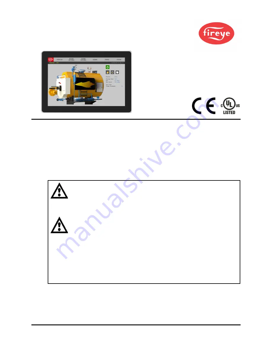


DESCRIPTION 

This bulletin describes the installation and operation of the NXTSD507HD (7”) and NXTSD512HD 

(12.1”) touchscreen interfaces. An overview of navigation through the available data as well as device-

specific information is covered.  
These optional devices allow for enhanced and expanded connectivity to the NXF4000 and PPC4000 

parallel-positioning systems. This bulletin is intended to be a supplement to the specific bulletin for 

any connected control. Those bulletins may be specified in this document. Please refer to those 

bulletins for any specific information on installation, features, commissioning or operation of the 

connected controls. 


WARNING: Failure to properly install, operate, or commission the equipment 

in this manual could result in significant property damage, severe injury, or 

death. It is the responsibility of the owner or user to ensure that the 

equipment described is installed, operated and commissioned in compliance 

with this manual as well as the manuals of other system components, as 

well with all applicable national and local codes.  


WARNING: Boiler operation, maintenance, and troubleshooting shall only be 

conducted by trained personnel. Persons troubleshooting lockouts or 

resetting the control must respond properly to troubleshooting error codes as 

described in this product bulletin. Jumpers being used to perform static test 

on the system must only be used in a controlled manner and must be removed 

prior to the operation of the control. Such tests may verify the external 

controllers, limits, interlocks, actuators, valves, transformers, motors and 

other devices are operating properly. Such tests must be conducted with 

manual fuel valves in the closed position only. Replace all limits and interlocks 

not operating properly, and do not bypass limits in interlocks. Failure to follow 

these guidelines may result in an unsafe condition hazardous to life and 

property. 


Summary of Contents for Fireye NXTSD507HD

Page 1: ...y or death It is the responsibility of the owner or user to ensure that the equipment described is installed operated and commissioned in compliance with this manual as well as the manuals of other sy...

Page 2: ...rnet USB 16 ESTABLISHING COMMUNICATION 17 OVERVIEW SCREEN NXF4000 and PPC4000 18 INFORMATION SCREEN NXF4000 and PPC4000 19 GENERAL SETTINGS NXF4000 and PPC4000 20 Changing values 20 SYSTEM SETTINGS 21...

Page 3: ...PRO 50 WIRING DIAGRAM SCREEN BurnerPRO 51 SETTINGS SCREEN BurnerPRO 52 OVERVIEW SCREEN ABB ACS550 53 MOTOR SCREEN ABB ACS550 54 SETTINGS SCREEN ABB ACS550 55 BACKUP RESTORE SCREEN ABB ACS550 56 REMOTE...

Page 4: ...topologies depending upon how many controls are connected and where they are located While there are no defined limits to the number of devices that can be connected to the NXTSD507HD and NXTSD512HD...

Page 5: ...ltage 24 VDC 20 Nominal power consumption 0 45A 24VDC 10 8W Operating temperature range 20 C to 50 C 4 F to 122 F Storage temperature range 30 C to 80 C 22 F to 176 F Degree of protection Indoor use o...

Page 6: ...voltage 24 VDC 20 Nominal power consumption 0 9A 24VDC 21 6W Operating temperature range 20 C to 50 C 4 F to 122 F Storage temperature range 30 C to 80 C 22 F to 176 F Degree of protection Indoor use...

Page 7: ...arate power and communication sold by the foot ED610 Multi port cable adapter for converting BurnerLogix or BurnerPRO modular jacks to terminal blocks ED512 2 Modular connection cable to connect Burne...

Page 8: ...the knurled head thumb nuts The thumb nuts attach to threaded posts which are threaded into inserts around the bezel of the screen See the figure to the right for a diagram of the thumb nut attached t...

Page 9: ...rk the necessary cutout and holes to mount the screen The orientation of the diagram is from the face of the panel where the cutout is being made A template is also provided on the following page that...

Page 10: ...10 2021 Carrier Template...

Page 11: ...m length provided The figure below shows the retaining clip The clips first latch into the perimeter of the screen from the rear using hooks As the screws are tightened they push against the back of t...

Page 12: ...12 2021 Carrier Cutout Use the following dimensions to mark the necessary cutout to mount the screen The orientation of the screen is with the widest dimension horizontal...

Page 13: ...terminals The connectors labeled 1 through 4 are the RS 485 serial ports used for Modbus RTU communication to the connected devices These connections are polarity sensitive and are designated on the l...

Page 14: ...erLogix YB110 YP138 with YZ300 annunciator plus an ABB ACS550 for the combustion air fan The best way to connect all of these devices to the NXTSD512HD would be to wire each burner s controls to a dif...

Page 15: ...ground on one end of the cable Normally this is not required as the twisted pair used for the communication wiring handles the noise rejection If either a third party power supply or a different cable...

Page 16: ...for Ethernet and USB There is one Ethernet port for connecting to a network and two type A USB ports for connecting to a keyboard mouse or USB drive A USB hub can be connected if needed to increase t...

Page 17: ...e default communication settings If the unit is not set for the default communication settings initiate the device discovery process as outlined for multiple controls in the SYSTEM Options Miscellaneo...

Page 18: ...also accessible by pressing the right most dropdown on the left menu bar and choosing OVERVIEW The FIREYE logo button will return to the device selection screen if multiple devices are connected The...

Page 19: ...bar and choosing INFORMATION will display the information screen All the same information from the home screen is available but there are also additional tabs for more detailed status information See...

Page 20: ...values Changing a value requires entering the appropriate user level passcode If this is needed a Security Control popup will prompt for this The user logon level can be changed but will automaticall...

Page 21: ...and choosing SYSTEM SETTINGS will display the submenu options for system settings Each of these submenu options will display a screen dedicated to a specific setting function See Fireye bulletin NXF...

Page 22: ...22 2021 Carrier ALARMS Pressing the ALARMS button right menu bar will display the alarms submenu...

Page 23: ...alarms will appear on any screen as a red banner with a button to dismiss the alarm banner The active alarm page accessible here will list any active alarms Dismissing the alarm banner will not remove...

Page 24: ...rm log screen will show the list of alarms sorted by date The date show is at the top of the screen and can be adjusted using the left and right arrows Each entry is date and time stamped Alarms for t...

Page 25: ...2021 Carrier 25 Fault History Pressing the right most dropdown on the left menu bar and choosing MENU FAULT HISTORY will display the complete fault history from the NXF4000 or PPC4000...

Page 26: ...n the left menu bar and choosing MENU HELP will display the icon legend This will help to identify what the icons designate if that is not known See Fireye bulletin NXF 4100 for additional information...

Page 27: ...ng file to the internal memory The file is a jpg type with a resolution that matches the connected screen This is 800x480 for the NXTSD507HD and 1280x800 for the NXTSD512HD These screen captures can b...

Page 28: ...28 2021 Carrier Log A system event log can be displayed to show not only all alarms but also every system event such as logins etc...

Page 29: ...ch the UNLOCK icon to complete the login The KEY icon allows the current user password to be changed Be careful when changing the Admin password since there is no way to restore the password to the de...

Page 30: ...anting the Logged out user rights to adjust parameters or click buttons This would allow the user to reset a lockout without logging in Note that any NXF4000 or PPC4000 parameter that requires local u...

Page 31: ...tions Pressing the OPTIONS button will allow the user to change screen options There are multiple pages within the options pressing the folder icon at the upper right corner will move between options...

Page 32: ...screen will then prompt for a device type Next the serial port that the device is connected to must be selected If the device is an NXF4000 or PPC4000 it will be automatically discovered as the NXTSD...

Page 33: ...2021 Carrier 33 If there is more than one device connected the FIREYE logo button on the upper left corner will display an overview of all devices Each device can then be navigated from here...

Page 34: ...ween Overview type shown on left in previous image or Status type shown on right in previous image This is chosen by pressing the folder icon on the upper right beside the CLOSE X icon then pressing t...

Page 35: ...points that each pen represents can be selected from the Modbus data points of any connected device Data can be mixed on the same graph between multiple devices and multiple different graphs and be cr...

Page 36: ...36 2021 Carrier Up to eight data points can be selected per graph Once selected they can be removed or new points added if the total doesn t exceed eight points...

Page 37: ...2021 Carrier 37 Once one or more trend graphs have been configured there will be a new menu item TRENDS that will list all the configured graphs on the submenu...

Page 38: ...e would be 20210721213553_NXF_OVERVIEW jpg Backup Configuration The device configuration can be saved to a USB file The file will be saved in the path FireyeHMI Backup cfg The backup file can be used...

Page 39: ...2021 Carrier 39 Language The selected language can be changed from this screen...

Page 40: ...ed on and off as well as the inactivity duration set Date The date and time can be set here The time will also be written to the connected NXF4000 or PPC4000 A common error when connecting to a newer...

Page 41: ...rrier 41 Network The network settings IP address subnet mask default gateway can be set from here These settings are used when connecting the Modbus TCP IP server or when using the remote VNC viewing...

Page 42: ...server is available and is enabled by default using node address 1 and port 502 These settings as well as the IP address settings can be changed See the section SYSTEM OPTIONS Network Modbus Data Ser...

Page 43: ...OPTIONS NETWORK Modbus Data Server page and press the button Export Tags This button will only be shown if there is a USB drive installed The data will be exported to the USB drive as two files Firey...

Page 44: ...al state can contain a value from 0 to 18 This number represents which functional state the NXF4000 or PPC4000 is in There needs to be a definition for each value to get meaning from this register To...

Page 45: ...erLogix is selected as a device pressing the right most dropdown on the left menu bar and choosing OVERVIEW will display the device overview screen See Fireye bulletin BL 1001 for additional informati...

Page 46: ...screen This screen will use green status lamps to indicate which inputs and outputs are active Once this screen is selected and additional dropdown menu allows selection of the proper programmer or mo...

Page 47: ...Logix If the BurnerLogix is selected as a device pressing the right most dropdown on the left menu bar and choosing MISC FAULT HISTORY will display the fault history screen The internal fault history...

Page 48: ...display the settings screen Options for the BurnerLogix are set from this screen The main options are if the YZ300 annunciator is connected as well as specifying the type of flame amplifier fitted If...

Page 49: ...he right most dropdown on the left menu bar and choosing YZ300 will display the YZ300 status screen The first limit that does not have the green status lamp on is the source of the shutdown In the exa...

Page 50: ...erPRO is selected as a device pressing the right most dropdown on the left menu bar and choosing OVERVIEW will display the device overview screen See Fireye bulletin BP 1004 for additional information...

Page 51: ...agram screen This screen will use green status lamps to indicate which inputs and outputs are active Once this screen is selected and additional dropdown menu allows selection of the proper programmer...

Page 52: ...eft menu bar and choosing MISC SETTINGS will display the settings screen Options for the BurnerPRO can be set from this screen These are the same options that can be set using the Config Wizard for Bu...

Page 53: ...S550 VFD is selected as a device pressing the right most dropdown on the left menu bar and choosing OVERVIEW will display the device overview screen See ABB ACS550 documentation for additional informa...

Page 54: ...ACS550 VFD is selected as a device pressing the right most dropdown on the left menu bar and choosing MOTOR will display the motor data screen See ABB ACS550 documentation for additional information o...

Page 55: ...own on the left menu bar and choosing SETTINGS will display the device settings screen All the registers that require modification as shown in Fireye bulletin NXF 4100 can be directly modified from th...

Page 56: ...lay the backup restore parameters screen The full set of modifiable settings for use with the NXF4000 or PPC4000 as described in Fireye bulletin NXF 4100 will be saved internally to the specified file...

Page 57: ...ewer software and then connect When prompted for a password use the VNC password fireye all lowercase If the eyeball icon appears on the upper right corner to the left of the SYSTEM submenu that indic...

Page 58: ...reof except lamps and photocells which is found defective in material or workmanship or which otherwise fails to conform to the description of the product on the face of its sales order THE FOREGOING...

Reviews: