


52
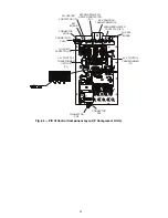
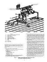
3. Wire the AC input leads by routing them through the
openings in the input power wiring panel.
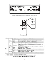
4. Connect the three-phase AC input power leads (per job
specifications) to the appropriate input terminals of the
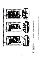
circuit breaker. See Fig. 10 and 11.
5. Tighten the AC input power terminals and lugs to the
proper torque as specified on the input circuit breaker.
CAUTION
Do not route signal and control wiring with power wiring
in the same conduit. This can cause interference with con-
trol and drive operation. Failure to observe this precaution
could result in damage to, or destruction of, the equipment.
Summary of Contents for EVERGREEN 23XRV
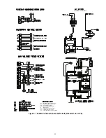
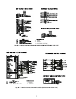
Page 53: ...53 Fig 60 Typical Field Wiring Schematic LF 2 VFD Shown NOTE See Notes for Fig 60 on page 56 ...
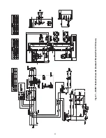
Page 54: ...54 Fig 60 Typical Field Wiring Schematic LF 2 VFD Shown cont a23 1585 ...
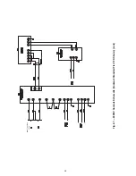
Page 55: ...55 Fig 60 Typical Field Wiring Schematic LF 2 VFD Shown cont a23 1586 ...
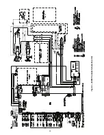
Page 60: ...60 Fig 63 23XRV Controls Schematic LF 2 ...
Page 64: ...64 FROM PREVIOUS PAGE Fig 67 23XRV Controls Schematic Rockwell Standard Tier VFD Shown cont ...