


93
o. Close remaining valves.
p. Turn off pumpout condenser water.
q. Turn off chiller water pumps, and lock out chiller
compressor.
Return Chiller to Normal Operating Conditions
1. Vapor Pressure Equalization:
a. Ensure that the chiller vessel that was exposed to
ambient has been evacuated. Final vacuum prior to
charging with refrigerant should in all cases be
29.9 in. Hg (500 microns, 0.07 kPa [abs]) or less.
b. Turn on chiller water pumps.
c. Open valves 1A, 1B, and 2.
d. Slowly open valve 4, gradually increasing pressure
in the evacuated vessel to 35 psig (241 kPa).
e. Leak test to ensure chiller vessel integrity.
f. Open valve 4 fully for cooler and condenser pres-
sure equalization (vapor equalization).
g. Close valves 1A, 1B, 2, and 4.
2. Liquid equalization:
a. If refrigerant is stored in cooler, install a charging
hose between valves 7 and 8, and open both the
valves and any other isolation valves (except valve
11) for liquid to drain into the condenser while
bypassing the linear float valve. If refrigerant is
stored in the condenser, keep valve 11 and any
other isolation valves open for liquid drain.
b. If valves 7 and 8 were used to bypass the linear
float valve, once the liquid transfer is complete,
close these valves, and slowly open valve 11.
c. Turn off chiller water pumps.
DISTILLING THE REFRIGERANT
1. Transfer the refrigerant from the chiller to the pumpout
storage tank as described in the Transfer Refrigerant from
Chiller to Storage Tank Vessel section.
2. Equalize the refrigerant pressure.
a. Turn on chiller water pumps and monitor chiller
pressures.
b. Close pumpout and storage tank valves 2, 4, 5, and
10, and close chiller charging valve 7; open chiller
isolation valve 11 and any other chiller isolation
valves, if present.
c. Open pumpout and storage tank valves 3 and 6;
open chiller valves 1a and 1b.
d. Gradually crack open valve 5 to increase chiller
pressure to 35 psig (241 kPa). Slowly feed refriger-
ant to prevent freeze-up.
e. Open valve 5 fully after the chiller pressure rises
above the freezing point of the refrigerant. Let the
storage tank and chiller pressure equalize.
3. Transfer remaining refrigerant.
a. Close valve 3.
b. Open valve 2.
c. Turn on pumpout condenser water.
d. Run the pumpout compressor until the storage tank
pressure reaches 5 psig (34 kPa), 18 in. Hg vacuum
(41 kPa absolute) in Manual or Automatic mode.
e. Turn off the pumpout compressor.
f. Close valves 1a, 1b, 2, 5, and 6.
g. Turn off pumpout condenser water.
4. Drain the contaminants from the bottom of the storage
tank into a container. Dispose of contaminants safely.
GENERAL MAINTENANCE
Refrigerant Properties —
The standard refrigerant for
the 19XR chiller is HFC-134a. At normal atmospheric pres-
sure, HFC-134a will boil at –14 F (–25 C) and must, therefore,
be kept in pressurized containers or storage tanks. The refriger-
ant is practically odorless when mixed with air and is noncom-
bustible at atmospheric pressure. Read the Material Safety
Data Sheet and the latest ASHRAE Safety Guide for Mechani-
cal Refrigeration to learn more about safe handling of this
refrigerant.
Adding Refrigerant —
Follow the procedures de-
scribed in Trim Refrigerant Charge section, page 95.
Adjusting the Refrigerant Charge —
If the addi-
tion or removal of refrigerant is required to improve chiller per-
formance, follow the procedures given under the Trim Refrig-
erant Charge section, page 95.
Refrigerant Leak Testing —
Because HFC-134a is
above atmospheric pressure at room temperature, leak testing
can be performed with refrigerant in the chiller. Use an elec-
tronic halogen leak detector, soap bubble solution, or ultrasonic
leak detector. Ensure that the room is well ventilated and free
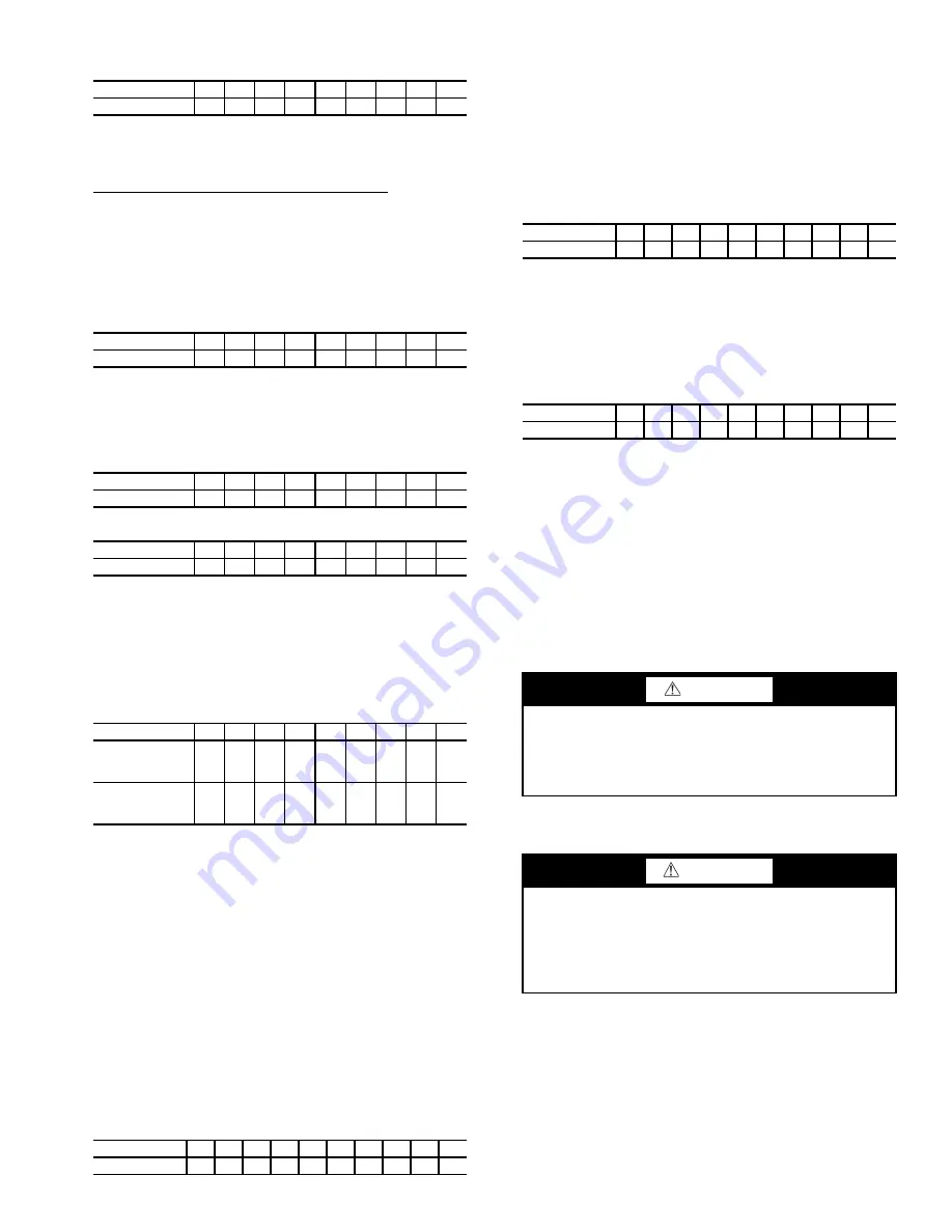
VALVE
1A
1B
2
3
4
5
7
8
11
CONDITION
C
C
C
C
C
C
C
C
C
VALVE
1A
1B
2
3
4
5
7
8
11
CONDITION
C
C
C
C
C
C
VALVE
1A
1B
2
3
4
5
7
8
11
CONDITION
C
C
C
C
C
VALVE
1A
1B
2
3
4
5
7
8
11
CONDITION
C
C
C
C
C
C
C
C
C
VALVE
1A
1B
2
3
4
5
7
8
11
CONDITION
(CHARGE IN
COOLER)
C
C
C
C
C
C
C
CONDITION
(CHARGE IN
CONDENSER)
C
C
C
C
C
C
C
C
VALVE
1A
1B
2
3
4
5
6
7
10
11
CONDITION
C
C
C
C
C
VALVE
1A
1B
2
3
4
5
6
7
10
11
CONDITION
C
C
C
C
VALVE
1A
1B
2
3
4
5
6
7
10
11
CONDITION
C
C
C
C
C
C
C
C
C
DANGER
HFC-134a will dissolve oil and some nonmetallic materi-
als, dry the skin, and, in heavy concentrations, may dis-
place enough oxygen to cause asphyxiation. When
handling this refrigerant, protect the hands and eyes and
avoid breathing fumes.
CAUTION
Always use the compressor pumpdown function in the
Control Test table to turn on the cooler pump and lock out
the compressor when transferring refrigerant. Liquid refrig-
erant may flash into a gas and cause possible freeze-up
when the chiller pressure is below 30 psig (207 kPa) for
HFC-134a.
Summary of Contents for AquaEdge 19XR series
Page 69: ...69 Fig 33 19XR Leak Test Procedures a19 1625 ...
Page 154: ...154 Fig 64 Benshaw Inc Wye Delta Unit Mounted Starter Wiring Schematic Low Voltage a19 1873 ...
Page 161: ...161 Fig 69 Typical Low Voltage Variable Frequency Drive VFD Wiring Schematic 575 v ...
Page 162: ...162 Fig 69 Typical Low Voltage Variable Frequency Drive VFD Wiring Schematic 575 v cont ...
Page 186: ...186 APPENDIX B LEAD LAG WIRING 19XR Lead Lag Schematic Series Cooler Flow a19 1655 ...
Page 187: ...187 APPENDIX B LEAD LAG WIRING cont 19XR Lead Lag Schematic Parallel Cooler Flow a19 1717 ...