background image

T-368

4–8

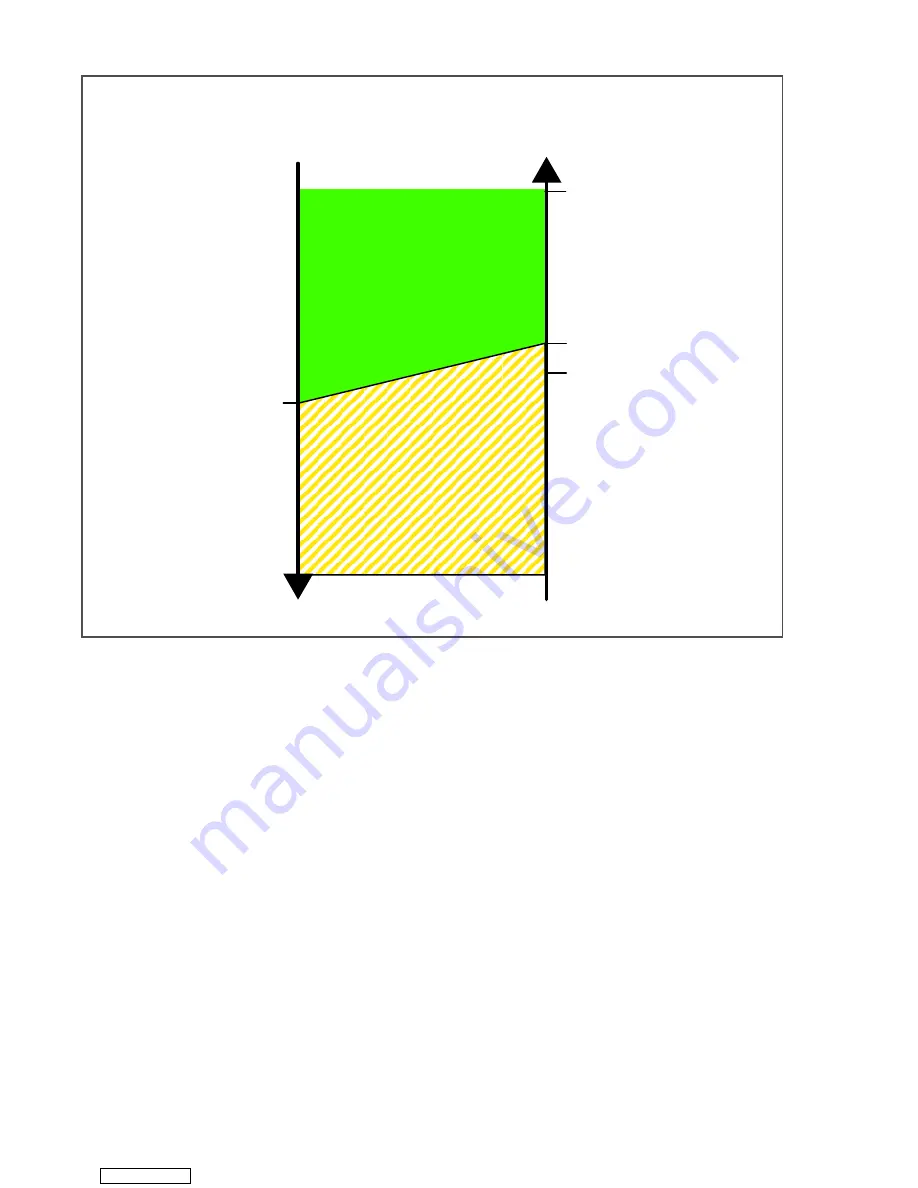
Figure 4.8 Controller Operation - Frozen Mode

4.3.13

Frozen Idle Mode

When temperature drops to set point minus 0.2°C
(0.36°F) and the compressor has run for at least five
minutes, the unit will transition to the frozen idle mode.
The compressor is turned off and the evaporator fans
continue to run to circulate air throughout the container.
If temperature rises above set point +0.2°C, (0.36°F)
the unit will transition back to the frozen steady state
mode.

NOTE

On start up of the unit, SMV will reset to a
known open position. This is accomplished
by assuming the valve was fully open, driv-
ing it fully closed, resetting the percentage
open to zero, then opening to a known 21%
staging position.

To prevent rapid cycling of the compressor, a three
minute compressor off time must be satisfied before
the compressor will restart. Under a condition of rapidly
changing return air temperature, the time delay may
allow the return air temperature to rise slightly above
set point temperature before the compressor can
restart.

4.3.14

Frozen “Heat” Mode

If the temperature drops 10°C (18°F) below set point,
the unit will transition to the frozen “heating” mode. The
evaporator fans are brought to high speed, and the
heat from the fans is circulated through the container.
The unit will transition back to frozen steady state when
the temperature rises back to the transition point.

4.3.15

Frozen Economy Mode

In order to activate economy frozen mode operation, a
frozen set point temperature must be selected, and
Cd34 (Economy Mode) set to “ON.” When economy
mode is active, the system will perform normal frozen
mode operations except that the entire refrigeration
system, excluding the controller, will be turned off when
the control temperature is less than or equal to the set
point -2°C (3.6°F).

After an off-cycle period of 60 minutes, the unit will turn
on high speed evaporator fans for three minutes and
then check the control temperature. If the control tem-
perature is greater than or equal to the frozen set point
+0.2°C (0.36°F), the unit will restart the refrigeration
system and continue to cool until the previously men-
tioned off-cycle temperature criteria are met. If the con-
trol temperature is less than the frozen set point +0.2°C
(0.36°F), the unit will turn off the evaporator fans and
restart another 60 minute off-cycle.

Controller Set Point at or BELOW 

ï

10

q

C (+14

q

F),

or 

ï

5

q

C (+23

q

F) optionally

ï

.20

q

C

+.20

q

C

Air Circulation

Cooling

Set Point

+2.5

q

C

(+4.5

q

F)

Frozen Mode

Falling

Temperature

Rising
Temperature

Downloaded from 

ManualsNet.com

 search engine

Summary of Contents for 69NT40-541-505

Page 1: ...Container Refrigeration OPERATIONS AND SERVICE MANUAL For 69NT40 541 505 508 and 509 Upflow Container Refrigeration Units T 368 Change 12 16 Downloaded from ManualsNet com search engine...

Page 2: ...Downloaded from ManualsNet com search engine...

Page 3: ...OPERATIONS AND SERVICE MANUAL For 69NT40 541 505 508 and 509 Upflow Container Refrigeration Units Carrier Corporation 2016 Printed in U S A December 2016 Downloaded from ManualsNet com search engine...

Page 4: ...Downloaded from ManualsNet com search engine...

Page 5: ...ondenser Coil 2 1 2 3 7 Condenser Grille 2 1 2 3 8 Evaporator 2 1 2 3 9 Evaporator Fan Operation 2 1 2 3 10 Plate Set 2 1 2 4 OPTION DESCRIPTIONS 2 1 2 4 1 Battery 2 1 2 4 2 USDA 2 1 2 4 3 Interrogato...

Page 6: ...re Control 4 4 4 3 2 Perishable Pulldown 4 4 4 3 3 Perishable Steady State 4 4 4 3 4 Perishable Idle Air Circulation 4 4 4 3 5 Perishable Heating 4 4 4 3 6 Perishable Mode Dehumidification 4 5 4 3 7 P...

Page 7: ...2 2 Connection to 190 230VAC Power option 5 1 5 3 ADJUST FRESH AIR MAKEUP VENT 5 1 5 3 1 Upper Fresh Air Makeup Vent 5 2 5 3 2 Vent Position Sensor 5 2 5 4 CONNECT REMOTE MONITORING RECEPTACLE 5 2 5...

Page 8: ...6 7 8 3 Compressor Reassembly 7 8 7 8 4 Preparation 7 9 7 8 5 Installing the Components 7 9 7 8 6 Compressor Oil Level 7 9 7 9 HIGH PRESSURE SWITCH 7 10 7 9 1 Checking High Pressure Switch 7 10 7 9 2...

Page 9: ...mming Procedure 7 21 7 20 4 Removing and Installing the Controller 7 22 7 20 5 Battery Replacement 7 23 7 21 TEMPERATURE SENSOR SERVICE 7 23 7 21 1 Sensor Checkout Procedure 7 23 7 21 2 Sensor Replace...

Page 10: ...Downloaded from ManualsNet com search engine...

Page 11: ...Make Up Air Flow Chart 5 2 Figure 7 1 Manifold Gauge Set 7 1 Figure 7 2 R 134a Manifold Gauge Hose Set 7 2 Figure 7 3 Service Valve 7 2 Figure 7 4 Refrigeration System Service Connections 7 4 Figure...

Page 12: ...am 8 2 Figure 8 3 Single Evaporator Fan Capability And VPS Unit Wiring Diagram 8 3 Figure 8 4 Single Evaporator Fan Capability And VPS Unit Wiring Diagram 8 4 Figure 8 5 Single Evaporator Fan Capabili...

Page 13: ...ble 4 7 Controller Pre Trip Test Codes 4 41 Table 4 8 DataCORDER Function Code Assignments 4 47 Table 4 9 DataCORDER Pre Trip Result Records 4 48 Table 4 10 DataCORDER Alarm Indications 4 49 Table 7 1...

Page 14: ...Downloaded from ManualsNet com search engine...

Page 15: ...cuit breaker and power supply to pre vent accidental energizing of circuit Do not bypass any electrical safety devices e g bridg ing an overload or using any sort of jumper wires Problems with the sys...

Page 16: ...NING Before disassembly of any external com pressor component make sure to relieve possible internal pressure by loosening the bolts and tapping the component with a soft hammer to break the seal CAUT...

Page 17: ...ION Ensure that the thrust washer does not fall off dowel pins while installing oil pump CAUTION The set screw on the crankshaft must be removed for this type of oil pump See Figure 6 8 CAUTION Use on...

Page 18: ...Downloaded from ManualsNet com search engine...

Page 19: ...trol Box Units are equipped with an aluminum control box and may be fitted with a lockable door 2 3 2 Controller The unit is equipped with a Micro Link 3 microproces sor system 2 3 3 Temperature Reado...

Page 20: ...individual circuit breaker for the 230 volt power If the unit is equipped with an autotransformer and communications module the autotransformer will be fitted with a trans former bridge unit TBU to a...

Page 21: ...to moderate the atmo spheric level in the container in response to cargo res piration When transporting frozen cargo loads the vent will be closed The upper left access panel contains the vent slide a...

Page 22: ...evaporator components are accessible by remov ing the upper rear panel as shown in Figure 3 2 Figure 3 2 Evaporator Section Units with Center Access Panel 1 Evaporator Fan Motor 1 2 Supply Recorder S...

Page 23: ...nd ambient sensor are located at the right side of the compressor Figure 3 3 Compressor Section 1 Quench Valve 2 Suction Modulating Valve 3 Suction Temperature Sensor 4 Quench Valve Temperature Bulb 5...

Page 24: ...he condenser fan pulls air from around the coil and dis charges it horizontally through the condenser fan grille Figure 3 4 Condenser Section 1 Condenser Coil 2 Sight Glass 3 Condenser Pressure Transd...

Page 25: ...over the ships main power line Refer to the master system technical manual for further information Figure 3 5 Control Box Section 1 Compressor Contactor CH 2 Compressor Phase A Contactor PA 3 Compress...

Page 26: ...er use air or gas mixtures containing oxygen O2 for leak testing or operating the product Charge Only With R 134a Refrigerant must conform to AHRI Standard 700 specification e Refrigerant R 134a Confo...

Page 27: ...to 77 2 ohms 20 C 68 F Type Sheath e Evaporator Fan Motor s 380 VAC 50 Hz 460 VAC 60 Hz Full Load Amps High Speed 1 6 2 1 Full Load Amps Low Speed 0 6 0 6 Nominal Horsepower High Speed 0 58 1 0 Nomin...

Page 28: ...Circuit Breaker CB 1 Manual Reset Trips at 29 amps 460VAC Circuit Breaker CB 2 50 amp Manual Reset Trips at 62 5 amps 230VAC Circuit Breaker CB 2 70 amp Manual Reset Trips at 87 5 amps 230VAC Excessiv...

Page 29: ...nt degree of superheat in the gas leaving the evaporator regardless of suction pressure The flow of liquid to the evaporator is regulated by a variable orifice which opens to increase refrigerant flow...

Page 30: ...ODULATING VALVE QUENCH VALVE BULB SIGHT GLASS MOISTURE INDICATOR RECEIVER EVAPORATOR CONDENSER FUSIBLE PLUG SERVICE VALVE QUENCH VALVE SIGHT GLASS SERVICE VALVE Discharge Liquid Suction LIQUID LINE VA...

Page 31: ...software is provided in Section 4 8 The keypad and display module serve to provide user access and readouts for both of the controller func tions temperature control and DataCORDER The functions are...

Page 32: ...Energized when an active or an inactive shutdown alarm is in the alarm queue CODE SELECT PRE TRIP ALARM LIST MANUAL DEFROST INTERVAL ENTER BATTERY POWER ALT MODE RETURN SUPPLY C F Table 4 1 Keypad Fun...

Page 33: ...de indications d Provide a Pre trip step by step checkout of refrig eration unit performance including proper compo nent operation electronic and refrigeration control operation heater operation probe...

Page 34: ...set points above 10 C 14 F When CnF26 is set to 5 C perishable mode is active with set points above 5 C 23 F 4 3 2 Perishable Pulldown When the system is in Perishable Pulldown Mode the highest priori...

Page 35: ...d is 2 below the dehumidi fication set point the high speed evaporator fans will be energized During dehumidification power is applied to the defrost heaters This added heat load causes the controller...

Page 36: ...to Off 3 The user changes the set point to one that is in the frozen range When bulb mode is disabled by any of the above the evaporator fan operation for dehumidification reverts to alt and the DTS t...

Page 37: ...F below set point contact TH opens to de energize the heaters The HEAT light is also de energized The evaporator fans continue to run to circulate air throughout the container c The safety heater term...

Page 38: ...ans are brought to high speed and the heat from the fans is circulated through the container The unit will transition back to frozen steady state when the temperature rises back to the transition poin...

Page 39: ...n the heaters which are located below the evapo rator coil During normal operation de icing will con tinue until temperatures indicate that the ice on the coil has been removed proper air flow has bee...

Page 40: ...run for eight minutes to stabilize the temperature throughout the con tainer A probe check comparison is carried out at the end of the eight minute period if any sen sor is found out of calibration At...

Page 41: ...130 F the HTT will open to de ener gize the heaters AL59 AL60 If the HTT does not open and termination does not occur within two hours the controller will terminate defrost AL60 will be acti vated to...

Page 42: ...ith the set point on the left display c The user should scroll through the alarm list to determine what alarms exist or have existed Alarms must be diagnosed and corrected before the Alarm List can be...

Page 43: ...nd temperature control software generated data and events as follows Container ID Change Software Upgrades Alarm Activity Battery Low Battery Pack Data Retrieval Defrost Start and End Dehumidification...

Page 44: ...lation valve percentage 10 Discrete outputs See Note 11 Discrete inputs See Note 12 Ambient sensor 13 Compressor suction sensor 14 Compressor discharge sensor 15 Return temperature sensor 16 Supply te...

Page 45: ...ading 1 Origin Origin Date Destination Discharge Date Comment DataLINE Tool Probe Calibration Readings USDA1 0 0 USDA2 0 0 USDA3 0 0 Cargo 0 0 Temperature Units Centigrade ____________________________...

Page 46: ...DER is finished recording it will power down During DataCORDER power up while using battery pack power the controller will perform a hardware volt age check on the battery If the hardware check passes...

Page 47: ...of the unit Four or five receptacles are provided The four three pin receptacles are for the probes and fifth five pin recep tacle is the rear connection for the Interrogator The probe receptacles are...

Page 48: ...m list will clear and will be displayed 4 Press the ALARM LIST key AL will show on the left display and on the right dis play when there are no alarms in the list 5 Upon clearing of the Alarm Queue th...

Page 49: ...rmer Out 0 out 1 in CnF22 Economy Mode Option OFF 0 off 1 full 2 std 3 cust CnF23 Defrost Interval Timer Save Option noSAv 0 no_sav 1 sav CnF24 Enable Long PreTrip Test Series Auto1 0 auto1 1 auto2 3...

Page 50: ...aporator 0 Out 1 in CnF60 Compressor Cycle Perishable Cooling 0 Out 1 in CnF61 ACT ASC Control Enable 0 Out 1 in CnF62 Extended Temperature Control Enable 0 Out 1 in CnF63 CCPC Pre trip Tripstart Defa...

Page 51: ...ermine if it falls within the expected range of values for the component Failure of this test will result in a pretrip failure or a control alarm indication Cd07 Main Power Voltage The main supply vol...

Page 52: ...troller was configured with a configuration card or with a valid OEM serial port configuration update YYMMDD rep resents the publication date of the model configuration database Cd21 ML3 Humidity Wate...

Page 53: ...n For units operating with PuLS selected defrost interval is determined by the unit temperature setpoint and the Evaporator Fan Pulsing Temperature Setting Cd60 When the unit temperature setpoint is e...

Page 54: ...re 15 17 19 21 Factory Default 23 Cd33 Humidity Setpoint This is the value in percent to which the system will dehumidify or humidify There are configuration variables that determine whether dehumidif...

Page 55: ...isplay the supply recorder sensor reading Cd39 Secondary Return Temperature Sensor Code Cd39 will display the current return recorder sensor RRS reading for units configured for four probes If the uni...

Page 56: ...should not be remembered as being detected not present Configurable Functions Cd45 through Cd48 are user selectable functions The operator can change the value of these functions to meet the operation...

Page 57: ...s OFF Evaporator speed select goes to Alt for units without PWM Compressor Control Cnf57 Out Evaporator speed select goes to Hi for units with PWM Compressor Control Cnf57 In DTT setting goes to 25 6...

Page 58: ...wn into a hierarchy of parameter se lection menus in the order listed above Pressing ENTER key in any of the param eter selection menus commits to selection of the currently displayed parameter and ca...

Page 59: ...second entry in the menu Turning ASC off clears this entry This ac tion also resets Cd53 to initial time remaining ASC must then be turned on to view or modify the additional parameters Whenever any a...

Page 60: ...ils repair Correct all faults Yes Yes Yes Yes No Yes No Yes No No No No Correct Refrigerant issue Unit OK Yes No Refer to CONNECT POWER Section 4 2 Refer to CONNECT POWER Section 4 2 Refer to CONTROLL...

Page 61: ...is in frozen mode Component Vent Position Sensor VPS Troubleshooting Manually reposition vent and confirm using Cd45 Refer to VENT POSI TION SENSOR SERVICE Section 7 22 Corrective Action If unable to...

Page 62: ...cle the unit Corrective Action Refer to Refrigerant Charge Section 7 7 Power cycle the unit AL20 CONTROL CONTACTOR FUSE F3 Cause Control power fuse F3A or F3B is open Component Check F3A if the fuse i...

Page 63: ...oting Shut down unit disconnect power check Evaporator Motor IP at plug connection pins 4 6 Corrective Action Replace defective evaporator fan motor refer to EVAPORATOR FAN MO TOR Service Section 7 14...

Page 64: ...passes no further action is required If P5 fails replace the defective sensor as determined by P5 refer to TEM PERATURE SENSOR Service Section 7 21 AL27 ANALOG TO DIGITAL ACCURACY FAILURE Cause Contr...

Page 65: ...icates defective controller memory Corrective Action Replace defective controller refer to Controller Service Section 7 20 AL52 EEPROM ALARM LIST FULL Cause Alarm list queue is full Component Active A...

Page 66: ...r to TEM PERATURE SENSOR Service Section 7 21 AL57 AMBIENT SENSOR AMBS Cause Invalid Ambient Temperature Sensor AMBS reading Component Ambient Temperature Sensor AMBS Troubleshooting Test the AMBS ref...

Page 67: ...n 7 21 2 AL61 HEATER CURRENT DRAW FAULT Cause Improper current draw during heat or defrost mode Component Heater s Troubleshooting While in heat or defrost mode check for proper current draw at heater...

Page 68: ...tion 7 21 AL65 DISCHARGE PRESSURE TRANSDUCER DPT Cause Compressor Discharge Transducer is out of range Component Compressor Discharge Transducer DPT Troubleshooting Confirm accurate DPT pressure readi...

Page 69: ...f range Component Secondary Return Sensor RRS Troubleshooting Perform Pre trip P5 Corrective Action If P5 passes no further action is required If P5 fails replace the defective sensor as determined by...

Page 70: ...xecuting ERR 3 N A N A ERR 4 N A N A ERR 5 A D failure The controller s Analog to Digital A D converter has failed ERR 6 IO Board failure Internal program update failure ERR 7 Controller failure Inter...

Page 71: ...ses if change in current draw is in the range specified P2 Tests Condenser Fan Current Draw Condenser fan is turned on then off Current draw must fall within specified range No other system components...

Page 72: ...if temperature comparison falls within the specified range NOTE If this test fails P50 and FAIL will be displayed If both Probe tests this test and the PRIMARY SECONDARY pass the display will read P5...

Page 73: ...ified range P6 1 P6 H P6 L Not Applicable These tests are not run for Single Speed Compressors P6 2 Suction Modulation Valve Open and Closed The compressor and fans continue to run from the previous t...

Page 74: ...CPT Return temperature sensor RTS Ambient sensor AMBS Test will also fail if HPS fails to open within 15 minutes Discharge temperature exceeds 138 C 280 F Discharge temperature is less than or equal...

Page 75: ...2 and the right display will show the supply air temperature When the test is completed the average control temperature error will be com pared to the pass fail criteria Test passes if the average tem...

Page 76: ...iner temperature down to the 17 7 C set point If this occurs within the three hour time limit the test passes If pulldown is not completed within the three hour time the test fails Upon failure and wh...

Page 77: ...dC26 27 S N Left 4 Right 4 The DataCORDER serial number consists of eight characters Function code dC26 contains the first four characters Function code dC27 con tains the last four characters This s...

Page 78: ...Fail Skip Result Change in currents for Phase A B and C 6 1 Not Applicable Not Used 6 2 Suction Modulation Valve Open and Closed Pass Fail Skip Result Is current or pressure limit in effect Y N 6 4 N...

Page 79: ...umber AL78 to AL85 is assigned to each configured point When an alarm occurs the DataCORDER must be interrogated to identify the data point assigned When a humidity sensor is installed it is usually a...

Page 80: ...Downloaded from ManualsNet com search engine...

Page 81: ...e clean and dry before connecting to power receptacle 5 2 1 Connection To 380 460 VAC Power 1 Make sure start stop switch ST on control panel and circuit breaker CB 1 in the control box are in positio...

Page 82: ...whenever the unit is running under AC power and any of the following Trip start On every power cycle Midnight Manual change greater than 5 CMH 3 CFM and remains in that position for at least four min...

Page 83: ...completion of Pre Trip activity economy dehumidifica tion and bulb mode must be reactivated Pre Trip diagnostics provides automatic testing of the unit components using internal measurements and comp...

Page 84: ...t the conclusion PASS or FAIL will be displayed This message will remain displayed for up to three minutes during which time a user may select another test If the three minute time period expires the...

Page 85: ...nvalidated If the unit is in perishable mode a probe alarm will be triggered for both return probes 5 9 EMERGENCY BYPASS OPERATION OPTION Operation by the refrigeration controller may be over ridden b...

Page 86: ...Downloaded from ManualsNet com search engine...

Page 87: ...ompressor hums but does not start Low line voltage Check Single phasing Check Shorted or grounded motor windings 7 8 Compressor seized 7 8 6 2 UNIT OPERATES LONG OR CONTINUOUSLY LONG IN COOLING Condit...

Page 88: ...power Circuit breaker or fuse defective Replace Control Transformer defective Replace Evaporator fan internal motor protector open 7 14 Heat relay defective Check Heater termination switch open 7 13 U...

Page 89: ...ormal 6 7 ABNORMAL PRESSURES COOLING Condition Possible Cause Remedy Refer ence Section High discharge pressure Condenser coil dirty 7 10 1 Condenser fan rotating backwards 7 11 Condenser fan inoperat...

Page 90: ...W OR RESTRICTED AIR FLOW Condition Possible Cause Remedy Refer ence Section Evaporator coil blocked Frost on coil 6 6 Dirty coil 7 13 No or partial evaporator air flow Evaporator fan motor internal pr...

Page 91: ...tion pressure Improper bulb location or installation 7 16 Low superheat setting 7 16 6 12 AUTOTRANSFORMER MALFUNCTION Condition Possible Cause Remedy Refer ence Section Unit will not start Circuit bre...

Page 92: ...Downloaded from ManualsNet com search engine...

Page 93: ...be checked at the Dis charge Pressure Gauge When both valves are backseated all the way out high pressure vapor will flow into the low side When the Suction Pressure Valve is open and the Dis charge...

Page 94: ...ccess Valve 3 Stem Cap 4 Valve stem 5 Compressor or Filter Drier Inlet Connection 6 Valve Frontseated 7 Valve Backseated Connection of the manifold gauge hose set see Fig ure 7 4 is dependent on the c...

Page 95: ...nd or property damage Never use air or gas mixtures containing oxygen O2 for leak testing or operating the product Charge Only With R 134a Refrigerant must conform to AHRI Standard 700 specification a...

Page 96: ...emove the copper tubing and change the filter drier Evacuate unit to 500 microns Close the electronic vacuum gauge and vacuum pump valves Shut off the vacuum pump Wait five minutes to see if vacuum ho...

Page 97: ...and check the refrigerant charge 7 7 3 Adding Refrigerant to System Partial Charge a Examine the unit refrigerant system for any evi dence of leaks Repair as necessary refer to Section 7 5 b Maintain...

Page 98: ...check refrigerant charge refer to Section 7 7 s Check moisture liquid indicator for wetness Change filter drier if necessary refer to Section 7 12 t Check compressor oil level per Section 7 8 6 Add oi...

Page 99: ...the piston rings extend above the cylinders CAUTION The copper tube that connects to the oil suction strainer extends out the bottom with the bottom plate removed Take pre cautions to avoid bending or...

Page 100: ...ube draw vapor from the crankcase Remove the rotor using a jack bolt Insert a brass plug into the rotor hole to pre vent damage to the end of the crankshaft k If the piston rings extend beyond the cyl...

Page 101: ...against crank bearings b Install the pump end thrust washer on the two dowel pins located on the bearing head see Figure 7 8 CAUTION Ensure that the thrust washer does not fall off dowel pins while in...

Page 102: ...nd oil will flow through the suction service valve into the compressor Add oil as necessary c Adding Oil to Service Replacement Compressor Service replacement compressors are shipped without oil If oi...

Page 103: ...t is powered off and the plug is disconnected b Remove the condenser fan grille c Starting from the top of the coil use a water hose with a nozzle to wash the coil from the inside out d Systematically...

Page 104: ...all a new filter drier g Replace the liquid line cushion clamps h Secure the receiver assembly to the side sup port bracket i Pressure leak test the coil and filter drier con nections refer to Section...

Page 105: ...the mounting bolts and adjust the motor posi tion on the bracket and then secure the motor k Remove the condenser fan and connect the fan motor wiring to the fan motor l Place the condenser fan on th...

Page 106: ...et con taining that heater may be disconnected at the contactor The next Pre trip P1 will detect that a heater set has been disconnected and indicate that the failed heater should be replaced To remov...

Page 107: ...eez Apply thread sealer Loc tite H brown in color to the two fan set screws Install fan on motor The evaporator fan locating dimension is shown in Figure 7 19 Figure 7 18 Evaporator Fan Locating Dimen...

Page 108: ...ter and 1 part cleaner d Allow the cleaner to soak in for 5 to 7 minutes e Assess area for rinsing Follow all local regula tions regarding disposal of waste water f Thoroughly rinse the cleaner and su...

Page 109: ...ation on the heaters and their wires 5 Open the insulation flap Flap is secured with Velcro Item 3 Figure 7 22 6 Loosen the thumb screw and slide the bulb out by pulling it towards the front of the un...

Page 110: ...nto control mode Both the discharge suction pressures and current draw will go signifi cantly lower Once below set point the suction pressure should go into a vacuum within several minutes Should the...

Page 111: ...n nections and replace the motor If near normal or nor mal reading occurs proceed to step 7 18 2 to check out the controller b Checking with SMA 12 portable stepper drive tester The SMA 12 portable st...

Page 112: ...s do not hold in check voltage supply c There is no internal protector for this transformer design therefore no checking of the internal protector is required d Using a voltmeter and with the primary...

Page 113: ...not applicable to the units cov ered herein TP 9 This test point is the chassis unit frame ground connection TP 10 This test point enables the user to check if the heat termination thermostat HTT cont...

Page 114: ...in the proper model dash number If a defective card is being used the display will blink the message bAd CArd Turn start stop switch OFF and remove the card 8 Press the ENTER key on the keypad 9 When...

Page 115: ...res from the battery along the display harness and connect the red battery wire and one end of the red jumper to KA14 the other end of the red jumper wire to KA11 and the black wire to KA13 h Replace...

Page 116: ...d wire to the shorter length e Strip back insulation on all wiring 6 3mm 1 4 inch f Slide a large piece of heat shrink tubing over the cable and place small pieces of heat shrink tub ing one over each...

Page 117: ...esh air VPS alarm AL50 will occur if the sensor reading is not stable for five minutes or if the sensor is outside of its valid range shorted or open This can occur if the vent is loose or the panel i...

Page 118: ...n the circuit breaker and communication interface module locations These wires are to be connected to the module and circuit breaker to allow the module to communicate over the power system To install...

Page 119: ...M FACTORY MINIMUM MAXIMUM WEAR BEFORE REPAIR inches mm inches mm inches mm MAIN BEARING Main Bearing Diameter Main Bearing Journal Diameter 1 6268 41 3207 1 6233 41 2318 0020 0020 0 0508 0 0508 PUMP E...

Page 120: ...Side Shield 6 10 8 13 Oil Pump Drive Segment 12 16 16 22 Unloader Valve 5 16 18 16 20 2 27 Cover Plate Plate End Bearing Head Terminal Block Cap Screws 20 30 27 41 Suction Valve Discharge Valve 3 8 16...

Page 121: ...00 4 90 6 21 3 7 25 5 0 26 0 26 75 24 78 7 542 6 5 53 5 43 4 20 4 6 31 7 0 32 0 32 80 27 86 7 597 8 6 10 5 98 2 19 5 6 36 6 0 39 0 39 85 29 95 3 657 1 6 70 6 57 0 18 6 5 44 8 0 46 0 45 90 32 104 3 71...

Page 122: ...as troubleshooting guide only for model series 69NT40 with fresh air makeup vent closed unit powered on 460VAC 60Hz and SMV 100 open Compressor Discharge Pressure Versus Ambient Air Temperature at St...

Page 123: ...17 8 C Box 48 9 43 3 37 8 32 2 26 7 21 1 15 6 35 F 1 7 C Box Compressor Suction Pressure Versus Ambient Air Temperature at Stable Box Temperature 8 9 10 11 12 13 14 15 16 17 60 70 80 90 100 110 120 A...

Page 124: ...Downloaded from ManualsNet com search engine...

Page 125: ...Downloaded from ManualsNet com search engine...

Page 126: ...Downloaded from ManualsNet com search engine...

Page 127: ...RICAL WIRING SCHEMATIC AND DIAGRAMS 8 1 INTRODUCTION This section contains the Electrical Schematics and Wiring Diagrams Figure 8 1 Single Evaporator Fan Capability And VPS Legend Downloaded from Manu...

Page 128: ...T 368 8 2 Figure 8 2 Single Evaporator Fan Capability And VPS Schematic Diagram Downloaded from ManualsNet com search engine...

Page 129: ...8 3 T 368 Figure 8 3 Single Evaporator Fan Capability And VPS Unit Wiring Diagram Downloaded from ManualsNet com search engine...

Page 130: ...T 368 8 4 Figure 8 4 Single Evaporator Fan Capability And VPS Unit Wiring Diagram Downloaded from ManualsNet com search engine...

Page 131: ...8 5 T 368 Figure 8 5 Single Evaporator Fan Capability and Emergency Bypass Legend Downloaded from ManualsNet com search engine...

Page 132: ...T 368 8 6 Figure 8 6 Single Evaporator Fan Capability and Emergency Bypass Schematic Diagram Downloaded from ManualsNet com search engine...

Page 133: ...8 7 T 368 Figure 8 7 Single Evaporator Fan Capability and Emergency Bypass Unit Wiring Diagram Downloaded from ManualsNet com search engine...

Page 134: ...T 368 8 8 Figure 8 8 Single Evaporator Fan Capability and Emergency Bypass Unit Wiring Diagram Downloaded from ManualsNet com search engine...

Page 135: ...8 9 T 368 Figure 8 9 Single Evaporator Fan Capability Emergency Bypass and Failsafe Legend Downloaded from ManualsNet com search engine...

Page 136: ...T 368 8 10 Figure 8 10 Single Evaporator Fan Capability Emergency Bypass and Failsafe Schematic Diagram Downloaded from ManualsNet com search engine...

Page 137: ...8 11 T 368 Figure 8 11 Single Evaporator Fan Capability Emergency Bypass and Failsafe Unit Wiring Diagram Downloaded from ManualsNet com search engine...

Page 138: ...T 368 8 12 Figure 8 12 Single Evaporator Fan Capability Emergency Bypass and Failsafe Unit Wiring Diagram Downloaded from ManualsNet com search engine...

Page 139: ...entification 2 1 Configuration Software CnF Variables 4 3 Connect Power 5 1 Connect Remote Monitoring Receptacle 5 2 Connection to 190 230VAC Power 5 1 Connection To 380 460 VAC Power 5 1 Control Box...

Page 140: ...e of Operation 4 7 Perishable Mode Temperature Control 4 4 Perishable Pulldown 4 4 Perishable Steady State 4 4 Perishable Dehumidification Bulb Mode 4 6 Physical Inspection 5 3 Plate Set 2 1 Pressure...

Page 141: ...ter Port 2 2 Thermostatic Expansion Valve 7 16 TXV Replacement 7 17 U Unit Introduction 2 1 Upper Air Fresh Air Make Up 2 2 Upper Fresh Air Makeup Vent 5 2 USDA 2 1 USDA Cold Treatment 4 17 USDA Cold...

Page 142: ...Downloaded from ManualsNet com search engine...

Page 143: ...f the United Technologies Corporation Stock symbol UTX Carrier Transicold Division Carrier Corporation P O Box 4805 Syracuse NY 13221 USA www carrier transicold com Downloaded from ManualsNet com sear...

Reviews: