background image

Table of Contents

Model Nomenclature 

3

General Information 

4

Pre-Installation 4

Vertical Installation 

5

Horizontal Installation 

6-8 

Condensate and Water Connections 

9

Integrated Variable-Speed Water Flow 

10

Control Heat Pump Applications Overview

Closed Loop Applications 

11

with Internal Flow Control

Flushing the Earth Loop 

12-14

Multiple Unit Piping and Flushing 

15-17

Ground Loop Applications 

18-19

Closed Loop - External Central 

20

Pumping Applications

Open Loop or Ground Water Systems 

21-22

Water Quality Requirements 

23 

Hot Water Generator 

24-26

Electrical - Line Voltage 

27

Electrical - Low Voltage Wiring 

28

Thermostat Wiring 

29

Wiring Diagrams 

30-33

ECM Blower Control 

34

Blower Data 

35

DXM2 Controls 

36-37

Low Water Temperature Cutout Selection 

37

Unit Commissioning 

38

and Operating Conditions 

Unit and System Checkout 

39

Unit Start-Up Procedure 

39-41

Unit Operating Conditions 

41-43

Performance Data (Full Load) 

44-49

Preventive Maintenance 

50

Troubleshooting  

51-52

DXM2 Troubleshooting 

53 

Functional & Performance Troubleshooting 

54-57

Troubleshooting Form 

58

Warranty  

59 

Revision History 

60

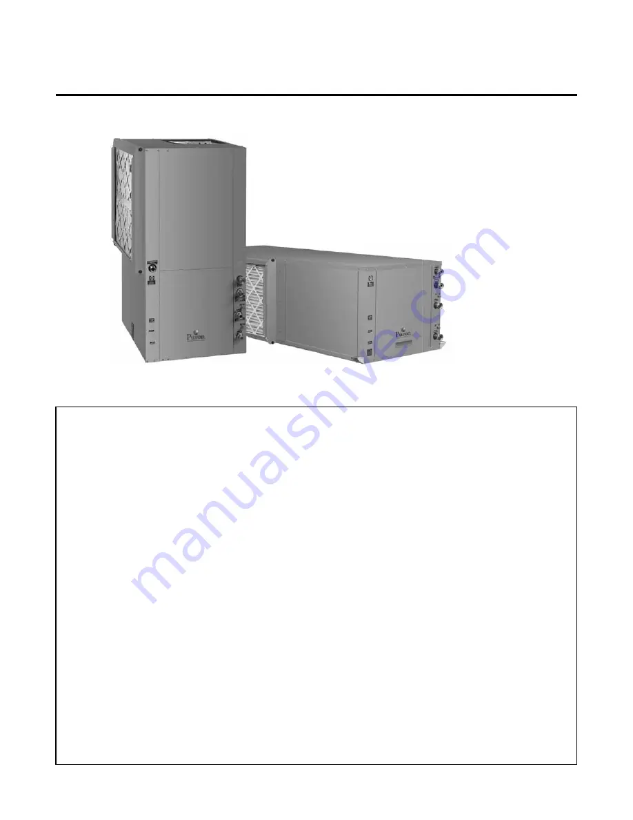
GT-PB Series (50YFV, 50YFH Models)

Installation, Operation and Maintenance Instructions

Residential Digital Horizontal & Vertical Packaged

Geothermal Heat Pumps

97B0046N05 

Rev: 4 April, 2014

Summary of Contents for 50YFH

Page 1: ...erator 24 26 Electrical Line Voltage 27 Electrical Low Voltage Wiring 28 Thermostat Wiring 29 Wiring Diagrams 30 33 ECM Blower Control 34 Blower Data 35 DXM2 Controls 36 37 Low Water Temperature Cutout Selection 37 Unit Commissioning 38 and Operating Conditions Unit and System Checkout 39 Unit Start Up Procedure 39 41 Unit Operating Conditions 41 43 Performance Data Full Load 44 49 Preventive Main...

Page 2: ...This page was intentionally left blank ...

Page 3: ...ury CAUTION Indicates a potentially hazardous situation or an unsafe practice which if not avoided could result in minor or moderate injury or product or property damage NOTICE Notification of installation operation or maintenance information which is important but which is not hazard related D DXM2 5 Motorized Valve Modulating Closed Loop Applications Low System Pressure Drop 6 Motorized Valve Mo...

Page 4: ...hipping information to verify that the correct unit has been shipped 2 Keep the cabinet covered with the original packaging until installation is complete and all plastering painting etc is finished 3 Verify refrigerant tubing is free of kinks or dents and that it does not touch other unit components 4 Inspect all electrical connections Connections must be clean and tight at the terminals 5 Remove...

Page 5: ...If the unit is located in a confined space such as a closet provisions must be made for return air to freely enter the space by means of a louvered door or other method Any access panel screws that would be difficult to remove after the unit is installed should be removed prior to setting the unit Refer to Figures 1 and 2 for typical installation illustrations Refer to unit catalog specifications ...

Page 6: ...e technician during the removal or replacement of the compressor and the removal or installation of the unit itself 2 Provide access to hanger brackets water valves and fittings Provide screwdriver clearance to access panels discharge collars and all electrical connections 3 DO NOT obstruct the space beneath the unit with piping electrical cables and other items that prohibit future removal of com...

Page 7: ...nternal Flow Controller Air Coil To obtain maximum performance the air coil should be cleaned before start up A 10 solution of dishwasher detergent and water is recommended for both sides of the coil A thorough water rinse should follow Figure 6b Typical Ground Water Horizontal Unit Installation with Internal Motorized Modulating Valve Pressure Tank by others Ball Valves Power Wiring Insulated sup...

Page 8: ...screws as shown in Figure 8 to free top panel and discharge panel 2 Lift out the access panel and set aside Lift and rotate the discharge panel to the other position as shown being careful with the blower wiring 3 Check blower wire routing and connections for tension or contact with sheet metal edges Reroute if necessary 4 Check refrigerant tubing for contact with other components 5 Reinstall top ...

Page 9: ...er external static pressure than other units connected to the same condensate main since this may cause poor drainage for all units on the line WHEN A VENT IS INSTALLED IN THE DRAIN LINE IT MUST BE LOCATED AFTER THE TRAP IN THE DIRECTION OF THE CONDENSATE FLOW Gasket Swivel Nut Stainless steel snap ring Brass Adaptor Hand Tighten Only Do Not Overtighten Figure 11 Water Connections Water Connection...

Page 10: ...nal Variable Speed Pump and other components to flush and operate the unit correctly including an expansion tank flush ports and flushing valves The pump speed is controlled by the DXM2 control based on the difference in entering and leaving water temperatures ΔT The Internal Flow Controller pump includes an internal check valve for multiple unit installations A copper water coil is standard with ...

Page 11: ...o metal threaded fittings should be avoided due to their potential to leak in earth coupled applications A flanged fitting should be substituted Earth loop temperatures can range between 25 and 110 F 4 to 43 C Flow rates between 2 25 and 3 Internal Flow Controller Chart 2 Internal Variable Speed Flow Controller Maximum Performance gpm per ton 2 41 to 3 23 l m per kW of cooling capacity is recommen...

Page 12: ...in all piping using a filter in the loop return line of the flush cart to eliminate debris from the loop system See Table 17 for flow rate required to attain 2fps 0 6 m s The steps below must be followed for proper flushing Units with internal variable speed pumps also include a check valve internal to the pump It is not possible to flush backwards through this pump Care must be taken to connect t...

Page 13: ...s purged from the system the level will drop only 3 8 in a 10 25 4 cm diameter PVC flush tank about a half gallon 1 9 liters since liquids are incompressible If the level drops more than this level flushing should continue since air is still being compressed in the loop fluid Do this a number of times NOTICE Actual flushing time require will vary for each installation due to piping length configur...

Page 14: ...Valve Position the flush cart from the Internal Flow Controller Install Flow Controller caps to ensure that any condensation leakage remains contained within the Flow Controller package If the loop pressure is between 50 and 75 psi 345 to 517 kPa upon completion of flushing pressures should be sufficient for all seasons NOTICE It is recommended to run the unit in the cooling then heating mode for ...

Page 15: ...an be found in Table 2 For example if a system includes two 2 ton units and four loop circuits we can calculate the flushing pressure drop as follows From Table 1 we know that it will take 4 gpm to flush each circuit If there is no provision to isolate the circuits for flushing we will have to flush with a minimum of 4 circuits x 4 gpm circuit 16 gpm total A check of other piping sizes used must b...

Page 16: ...rnal Flushing Valves Multiple Unit Piping and Flushing Again flush the loop through the internal flushing valves This is important as there may be air debris in the lines from this unit to the common piping Once flushing begins the air will be move into the loop and will need to be flushed out After the loop is flushed through the second unit change the flushing valves to flush the second unit Thi...

Page 17: ...ral variable speed pump In this case units with closed loop modulating valves are used do not use open loop modulating valves on a closed loop system External flushing valves are required This application is for larger systems including commercial Before flushing the installer should manually open all modulating valves as detailed in Closed Loop External Central Pumping section of this manual Next...

Page 18: ...ure Initially calculate the total volume of fluid in the piping system using Table 3 Then use the percentage by volume shown in Table 4 for the amount of antifreeze Antifreeze concentration should be checked from a well mixed sample using a hydrometer to measure specific gravity Contact your distributor if you have any questions as to antifreeze selection Antifreeze Charging It is highly recommend...

Page 19: ...ful is required the tank should be drained immediately by opening the waste valve of the flush cart noting the color of the discharge fluid Adding food coloring to the antifreeze can help indicate where the antifreeze is in the circuit and prevents the dumping of antifreeze out the waste port Repeat if necessary 5 Be careful when handling methanol or any alcohol Always wear eye protection and rubb...

Page 20: ...l from the DXM2 board AND 24V power it will remain in the same position it was in when it lost 24V power Note The Cv flow coefficient of the valve used in these units is DIFFERENT that the Cv of the valve used in the open loop unit It is not advisable for use in open loop applications as sound noise issues may result Units with the water circuit for closed loop central pumping option are only avai...

Page 21: ...tem Schrader ports built into unit may be used to measure heat exchanger pressure drop Water temperature can be viewed on the communicating thermostat Piping materials should be limited to copper PE or PVC SCH80 Note Due to the pressure and temperature extremes PVC SCH40 is not recommended Water quantity should be plentiful and of good quality Consult Table 5 for water quality requirements Integra...

Page 22: ...ion tank that is too small can cause premature pump failure due to short cycling Variable speed pumping applications should be considered for the inherent energy savings and smaller pressure tank requirements Water Coil Low Temperature Limit Setting For all open loop systems the 30 F 1 1 C LT1 setting factory setting water should be used to avoid freeze damage to the unit See Low Water Temperature...

Page 23: ...f 1 8 m s Filtered for maximum 841 micron 0 84 mm 20 mesh size 10 ppm 1 ppm sandfree for reinjection of particles and a maximum velocity of 1 8 m s Filtered for maximum 841 micron 0 84 mm 20 mesh size Any particulate that is not removed can potentially clog components Notes Rev 3 22 2012 15 Application not recommended 1R GHVLJQ 0D LPXP ORVHG 5HFLUFXODWLQJ V VWHP LV LGHQWLILHG E D closed pressurize...

Page 24: ...ed by the lower element The upper 20 of the tank or 10 gallons will be maintained at 125 F controlled by the upper element Using a 125 F set point the HWG can heat the lower 40 gallons of water from 100 F to 125 F providing up to 8 330 btu s of heat Using the 150 F set point the HWG can heat the same 40 gallons of water from 100 F to 150 F and the remaining 10 gallons of water from 125 F to 150 F ...

Page 25: ... THAT EMPLOY AN APPROVED ANTI SCALD VALVE PART NUMBER AVAS4 AT THE HOT WATER STORAGE TANK WITH SUCH VALVE PROPERLY SET TO CONTROL WATER TEMPERATURES DISTRIBUTED TO ALL HOT WATER OUTLETS AT A TEMPERATURE LEVEL THAT PREVENTS SCALDING OR BURNS C H M WATER HEATER CHECK VALVE 8 MAX HOT WATER TO HOUSE ANTI SCALD VALVE ANTI SCALD VALVE PIPING CONNECTIONS COLD WATER SUPPLY Installation The HWG is controll...

Page 26: ...ed cell insulation 3 Open both shut off valves and make sure the tank drain valve is closed Water Tank Refill 1 Close valve 4 Ensure that the HWG valves valves 2 and 3 are open Open the cold water supply valve 1 to fill the tank through the HWG piping This will force water flow through the HWG and purge air from the HWG piping 2 Open a hot water faucet to vent air from the system until water flows...

Page 27: ...ler Table 7b GT PB 50YF Series Electrical Data with Modulating Valve Model Compressor HWG Pump FLA Fan Motor FLA Total Unit FLA Min Circuit Amps Max Fuse HACR RLA LRA Qty 024 11 7 58 3 1 0 5 3 9 16 1 19 0 30 030 13 1 73 0 1 0 5 3 9 17 5 20 7 30 036 15 3 83 0 1 0 5 3 9 19 7 23 5 35 042 17 9 96 0 1 0 5 5 2 23 6 28 0 45 048 21 2 104 0 1 0 5 5 2 26 9 32 2 50 060 27 1 152 9 1 0 5 6 9 34 5 41 2 60 Rated...

Page 28: ...ssory Relays Accessory Terminal The DXM2 controller includes two accessory relays ACC1 and ACC2 Each relay includes a normally open NO and a normally closed NC contact Accessory relays may be configured to operate as shown in Tables 8a and 8b Table 8b Accessory Relay 2 Configuration Table 8a Accessory Relay 1 Configuration DIP 2 1 DIP 2 2 DIP 2 3 ACC1 Relay Option ON ON ON Cycle with fan OFF ON ON...

Page 29: ...b Conventional 3 Heat 2 Cool Thermostat Connection to DXM2 Control Thermostat Compressor Compressor Stage 2 Reversing Valve Fan 24Vac Hot 24Vac Common Fault LED DXM2 Board Y1 Y2 W H O G R C AL1 Y1 Y2 W DH O G R C L Dehumidification Notes Auxiliary Heat 1 ECM automatic dehumidification mode operates with dehumidification airflows in the cooling mode when the dehumidification output from thermostat ...

Page 30: ...Series 60Hz Puron R ev 4 April 14 30 DXM2 Wiring Diagram with Internal Flow Controller 96B0005N60 This diagram includes typical wiring details but is not applicable to all units For specific unit wiring refer to the diagram or the units control panel ...

Page 31: ...ries 60Hz Puron Rev 4 A pri l 1 4 DXM2 Wiring Diagram with Internal Flow Controller 96B0005N60 This diagram includes typical wiring details but is not applicable to all units For specific unit wiring refer to the diagram or the units control panel ...

Page 32: ...ies 60Hz Puron R ev 4 April 14 32 DXM2 Wiring Diagram with Motorized Modulating WaterValve 96B0005N62 This diagram includes typical wiring details but is not applicable to all units For specific unit wiring refer to the diagram or the units control panel ...

Page 33: ...s 60Hz Puron Rev 4 A pri l 1 4 DXM2 Wiring Diagram with Motorized Modulating WaterValve 96B0005N62 This diagram includes typical wiring details but is not applicable to all units For specific unit wiring refer to the diagram or the units control panel ...

Page 34: ...mum limits shown in Table 9 The blower operating modes include First Stage Cooling Y1 O Second Stage Cooling Y1 Y2 O First Stage Cooling in Dehumidification Mode Y1 O Dehumid Second Stage Cooling in Dehumidification Mode Y1 Y2 O Dehumid First Stage Heating Y1 Second Stage Heating Y1 Y2 Third Stage Auxiliary Heating Y1 Y2 W Emergency Heating W with no Y1 or Y2 Fan G with no Y1 Y2 or W It is necessa...

Page 35: ...0 1000 700 1100 1100 1100 1100 Minimum 750 525 750 525 750 525 375 750 036 0 6 1 2 Default 1125 750 975 650 1125 750 525 1125 Maximum 1250 950 1200 800 1250 1250 1250 1250 Minimum 900 600 900 600 900 600 450 900 042 0 6 3 4 Default 1300 925 1125 825 1300 925 600 1300 Maximum 1475 1100 1400 1000 1475 1475 1475 1475 Minimum 1050 750 1050 750 1050 750 525 1050 048 0 75 3 4 Default 1500 1125 1300 975 ...

Page 36: ...it Thermostat compatibility It is strongly recommended that communicating thermostat ATC32U or configuration diagnostic tool ACDU be used with DXM2 control to ensure easy configuration monitoring and diagnostics in PLAIN English For example Airflow CAN NOT be configured without either the communicating thermostat or configuration diagnostic tool Field Hardware Configuration Options Note In the fol...

Page 37: ...ory relays refer to DXM2 AOM for configuration Figure 32 DXM2 Layout and Connections Figure 31 LT1 Limit Setting Comp Relay 24Vdc EH1 EH2 P6 Off On JW3 c1 ay c2 ay CO RV RV LT2 LT2 P7 CC CCG CO S1 S2 12 1 4 Off On AO2 P11 Gnd T1 P10 T2 T2 T3 T3 T4 T4 T5 P9 T5 T6 T6 A0 1 A0 2 Off On S3 RV Relay CCH Relay 1 2 3 4 1 2 3 4 5 6 7 8 1 2 3 4 5 6 7 8 O1 Gnd DXM2 PCB JW3 LT1 jumper should be clipped for lo...

Page 38: ...ating conditions Minimum maximum limits are start up conditions to bring the building space up to occupancy temperatures Units are not designed to operate under these conditions on a regular basis 2 Voltage utilization complies with AHRI Standard 110 Cooling Heating Air Limits Min ambient air DB 45ºF 7ºC 39ºF 4ºC Rated ambient air DB 80 6ºF 27ºC 68ºF 20ºC Max ambient air DB 130ºF 54ºC 85ºF 29ºC Mi...

Page 39: ...es are open Line voltage and wiring Verify that voltage is within an acceptable range for the unit and wiring and fuses breakers are properly sized Verify that low voltage wiring is complete Unit control transformer Insure that transformer has the properly selected voltage tap Residential 208 230V units are factory wired for 230V operation unless specified otherwise Loop water piping is complete a...

Page 40: ...air delivery at the unit grille within a few minutes after the unit has begun to operate NOTE Units have a five minute time delay in the control circuit that can be bypassed on the DXM2 control board by placing the unit in the Test mode as shown in the unit IOM Check for normal air temperature rise of 20 F to 30 F heating mode c Verify that the compressor is on and that the water temperature fall ...

Page 41: ... 1 5 2 2 2 9 0 1 0 7 1 1 1 8 2 4 0 1 0 7 1 1 1 7 2 3 042 3 8 5 3 7 5 7 9 10 5 1 7 2 7 4 5 4 8 7 4 1 0 1 8 3 1 3 4 5 4 0 9 1 6 2 8 3 1 4 9 0 9 1 5 2 6 2 9 4 7 048 4 5 6 0 6 8 9 0 12 0 1 4 2 0 2 5 4 0 6 5 1 1 1 7 2 1 3 4 5 5 0 9 1 4 1 8 3 0 4 9 0 8 1 3 1 7 2 7 4 5 060 Rev B 6 0 7 5 9 0 12 0 15 0 1 2 2 1 3 1 5 4 8 1 0 9 1 7 2 5 4 6 7 0 0 8 1 5 2 3 4 2 6 4 0 8 1 4 2 2 3 9 6 1 Based on 15 methanol anti...

Page 42: ...8 98 96 106 105 115 353 373 361 381 370 390 9 14 10 15 10 15 14 19 14 19 14 19 13 2 15 2 9 0 11 0 4 8 6 8 24 29 25 30 26 31 70 1 5 2 25 3 128 138 124 134 119 129 310 330 290 310 270 290 10 15 10 15 11 16 11 16 10 15 8 13 19 21 14 1 16 1 9 2 11 2 18 23 18 23 18 23 116 126 128 138 139 149 390 410 406 426 419 439 11 16 12 17 14 19 15 20 15 20 15 20 17 0 19 0 11 6 13 6 6 1 8 1 29 34 31 36 32 37 90 1 5...

Page 43: ...20 25 20 25 94 104 100 110 105 115 343 363 350 270 356 376 9 14 10 15 10 15 12 18 11 16 10 15 11 3 13 3 8 2 10 2 5 0 8 0 25 30 26 31 26 31 70 1 5 2 25 3 124 134 124 134 123 133 300 320 278 298 256 276 8 13 8 13 8 13 14 19 11 16 9 14 19 9 21 9 14 1 16 1 8 3 10 3 19 24 19 24 19 24 122 132 130 140 137 147 377 397 386 406 394 414 11 16 12 17 13 18 9 14 8 13 7 12 14 2 16 2 10 3 12 3 6 5 8 5 31 36 31 36...

Page 44: ... 30 6 1 98 4 5 23 8 117 2 62 1 3 9 6 0 2 2 5 2 750 27 1 18 2 1 44 18 8 32 0 80 7 2 4 6 0 2 2 5 2 750 31 1 1 90 4 8 24 6 108 4 61 8 3 8 80 3 0 0 5 1 1 600 23 9 15 8 1 72 13 9 29 8 99 8 3 9 3 0 0 5 1 1 600 30 9 1 99 4 6 24 2 117 8 63 9 4 0 3 0 0 5 1 1 750 24 5 17 1 1 83 13 4 30 7 100 5 4 0 3 0 0 5 1 1 750 31 5 1 91 4 8 25 0 108 9 63 4 3 9 4 5 1 2 2 7 600 24 8 16 1 1 58 15 7 30 2 93 4 3 3 4 5 1 2 2 7...

Page 45: ...2 720 31 4 18 9 1 7 18 2 37 3 79 9 2 8 7 5 3 1 7 2 720 37 9 2 5 4 4 29 2 119 62 2 4 6 7 5 3 1 7 2 900 32 2 20 5 1 8 17 6 38 4 80 2 2 9 7 5 3 1 7 2 900 38 6 2 4 4 6 30 2 110 61 9 4 5 80 3 8 1 1 2 5 720 28 3 17 7 2 1 13 5 35 5 98 9 4 4 3 8 1 1 2 5 720 38 5 2 6 4 4 29 8 120 64 1 4 7 3 8 1 1 2 5 900 29 0 19 2 2 2 13 0 36 7 99 6 4 6 3 8 1 1 2 5 900 39 2 2 5 4 7 30 8 110 63 6 4 6 5 6 1 9 4 4 720 29 4 18...

Page 46: ... 2 98 4 4 35 0 115 5 62 2 5 7 9 0 2 4 5 5 1150 38 8 26 9 2 02 19 2 45 7 80 2 3 1 9 0 2 4 5 5 1150 46 0 2 87 4 7 36 2 107 0 62 0 5 5 80 4 5 0 1 0 3 920 34 7 23 4 2 36 14 7 42 7 99 0 5 2 4 5 0 1 0 3 920 45 8 3 03 4 4 35 5 116 1 64 2 5 9 4 5 0 1 0 3 1150 35 5 25 5 2 51 14 1 44 1 99 6 5 4 4 5 0 1 0 3 1150 46 6 2 91 4 7 36 7 107 5 63 7 5 7 6 8 1 1 2 5 920 35 8 23 9 2 19 16 4 43 3 92 8 4 5 6 8 1 1 2 5 9...

Page 47: ...40 45 0 31 4 2 4 18 9 53 2 80 1 2 9 10 5 4 9 11 3 1 040 52 6 3 6 4 3 40 5 117 62 3 5 7 10 5 4 9 11 3 1300 46 1 34 1 2 5 18 2 54 8 80 4 3 0 10 5 4 9 11 3 1 300 53 5 3 4 4 6 41 9 108 62 0 5 5 80 5 3 1 5 3 5 1040 41 0 29 5 2 9 14 1 50 9 99 4 4 6 5 3 1 5 3 5 1 040 53 5 3 6 4 4 41 2 118 64 3 5 8 5 3 1 5 3 5 1300 42 0 32 2 3 1 13 5 52 6 100 0 4 7 5 3 1 5 3 5 1 300 54 4 3 4 4 6 42 6 109 63 8 5 6 7 9 3 0 ...

Page 48: ...0 57 2 3 4 5 0 45 6 105 59 9 5 3 12 0 4 9 11 3 1200 50 1 32 1 2 7 18 7 59 2 79 9 3 8 12 0 4 9 11 3 1 200 57 6 3 5 4 8 45 5 114 62 4 5 6 12 0 4 9 11 3 1500 51 3 34 9 2 9 18 0 61 0 80 2 4 0 12 0 4 9 11 3 1 500 58 6 3 4 5 0 46 9 106 62 2 5 4 80 6 0 1 4 3 3 1200 45 4 30 3 3 4 13 3 57 0 99 0 6 0 6 0 1 4 3 3 1 200 58 6 3 6 4 8 46 5 115 64 5 5 7 6 0 1 4 3 3 1500 46 5 33 0 3 6 12 8 58 9 99 6 6 2 6 0 1 4 3...

Page 49: ... 4 5 55 7 113 5 62 0 7 1 14 0 5 6 13 0 1900 67 8 45 6 3 51 19 3 79 7 81 4 4 1 14 0 5 6 13 0 1900 72 7 4 43 4 8 57 6 105 4 61 8 6 9 80 7 0 1 2 2 8 1520 61 1 40 1 4 03 15 2 74 8 101 4 6 2 7 0 1 2 2 8 1520 72 5 4 64 4 6 56 7 114 2 63 8 7 2 7 0 1 2 2 8 1900 62 6 43 6 4 29 14 6 77 2 102 1 6 4 7 0 1 2 2 8 1900 73 8 4 46 4 8 58 6 106 0 63 3 7 0 10 5 3 1 7 1 1520 63 0 40 8 3 75 16 8 75 8 94 4 5 3 10 5 3 1...

Page 50: ...lters should be inspected every month under normal operating conditions and be replaced when necessary Units should never be operated without a filter Washable high efficiency electrostatic filters when dirty can exhibit a very high pressure drop for the fan motor and reduce air flow resulting in poor performance It is especially important to provide consistent washing of these filters in the oppo...

Page 51: ...240 8 0 43 47 116 6 4 04 117 242 6 0 42 48 118 4 3 89 118 244 4 0 41 49 120 2 3 74 119 246 2 0 40 50 122 0 3 60 120 248 0 0 39 51 123 8 3 47 121 249 8 0 38 52 125 6 3 34 122 251 6 0 37 53 127 4 3 22 123 253 4 0 36 54 129 2 3 10 General If operational difficulties are encountered perform the preliminary checks below before referring to the troubleshooting charts Verify that the unit is receiving el...

Page 52: ...ntrol Diagnostics menus allow the installer to see the current status of all DXM2 control switch inputs values of all temperature sensor inputs control voltage ECM blower internal flow center and proportional valve operating status and parameters Dipswitch Configuration The Dipswitch Configuration menus allow the installer to easily see the current DXM2 control configuration Fault History In addit...

Page 53: ...ttempt to Start Did Unit Lockout at Start up Unit Short Cycles Only Fan Runs Only Compressor Runs Did unit lockout after a period of operation Does unit operate in cooling Unit is OK See Performance Troubleshooting for further help Check Main power see power problems Check fault code on communicating thermostat ATC32 or Configuration and Diagnostics Tool ACD01 Yes No No No No No Yes No Yes See fau...

Page 54: ...hydrometer X Improper low temperature setting 30 F vs 10 F Clip LT1 jumper for antifreeze 10 F use X Water t emperature out of range Bring water temp within design parameters X X Bad thermistor Check temp and impedance correlation per chart LT2 Fault Code 5 Low Air Temperature X Reduced or no air flow Check for dirty air filter and clean or replace in cooling Check fan motor operation and airflow ...

Page 55: ...t air bring entering air temp within design parameters No Fault Code Shown X X No compressor operation See Only Fan Operates X X Compressor overload Check and replace if necessary X X Control board Reset power and check operation Unit Short Cycles X X Dirty air filter Check and clean air filte r X X Unit in Test Mode Reset power or wait 20 minutes for auto exit X X Unit selection Unit may be overs...

Page 56: ...ll ground moisture High Head Pressure X Reduced or no air flow Check for dirty air filter and clean or replace in heating Check fan motor operation and airflow restrictions Too high of external static check static vs blower table X Reduced or no water flow Check pump operation or valve operation setting in cooling Check water flow adjust to proper flow rate X Inlet water too hot Check load loop si...

Page 57: ...or X X Thermostat wiring Check thermostat wiring at or DXM2 Put in Test Mode and then jumper Y1 and W1 to R to give call for fan compressor and electric heat Unit Doesn t Operate in Cooling X Reversing Valve Set for cooling demand and check 24VAC on RV coil If RV is stuck run high pressure up by reducing water flow and while operating engage and disengage RV coil voltage to push valve X Thermostat...

Page 58: ... Water units only Temp Diff Temp Diff Water to Water units only Water to Water units only Temp Diff Heating Description Notes Cooling COMPRESSOR DISCHARGE SUCTION HWG AIR COIL EXPANSION VALVE FILTER DRIER REVERSING VALVE HEATING POSITION COOLING POSITION 1 COAX COAX 5 12 10 13 11 14 15 9 7 8 6 4 3 2 LT2 HEATING LIQUID LINE 5 LT1 COOLING LIQUID LINE CONDENSER HEATING EVAPORATOR COOLING CONDENSER HT...

Page 59: ...WLRQ PDLQWHQDQFH UHSDLU ZLULQJ RU YROWDJH FRQGLWLRQV 3URGXFWV VXEMHFWHG WR DFFLGHQW PLVXVH QHJOLJHQFH DEXVH ÀUH ÁRRG OLJKWQLQJ XQDXWKRUL HG DOWHUDWLRQ PLVDSSOLFDWLRQ FRQWDPLQDWHG RU FRUURVLYH DLU RU OLTXLG VXSSO RSHUDWLRQ DW DEQRUPDO DLU RU OLTXLG WHPSHUDWXUHV RU ÁRZ UDWHV RU RSHQLQJ RI WKH UHIULJHUDQW FLUFXLW E XQTXDOLÀHG SHUVRQQHO 0ROG IXQJXV RU EDFWHULD GDPDJHV RUURVLRQ RU DEUDVLRQ RI WKH SURGX...

Page 60: ... 745 6058 The Manufacturer works continually to improve its products As a result the design and specifications of each product at the time for order may be changed without notice and may not be as described herein Please contact the Manufacturer s Customer Service Department at 1 405 745 6000 for specific information on the current design and specifications Statements and other information contain...

Reviews: