


2–13
62-11640
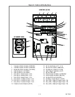
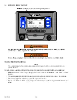
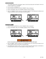
Figure 2.8 Light Bar
2.6.2
Remote Switch(es)
The unit is provisioned to connect remote switches
(DS/REMS1/REMS2) directly to the control system
through the REM connector to the SVM.
• Two types of switches may be used:
1. A switch with contacts that are open when the
switch is activated.
2. A switch with contacts that are closed when the
switch is activated.
• Four Configurations are available for each switch.
1. Activate an alarm only while the switch is acti-
vated.
2. Activate an alarm and shut the unit down while
the switch is activated. The unit will remain shut
down for a minimum of 3 minutes under this set-
ting.
3. Activate the alarm and bring the engine into low
speed while the switch is activated.
4. Record the switch activation in the DataLink
data recorder.
• If configured to shut the unit down or bring the
engine to low speed an additional choice will be
available. The additional choice allows the unit to
be set so that the configured action will always
take place OR the configured action will only take
place when the ambient temperature is below a
certain temperature. For example, if the shut-
down/low speed temperature choice is set to 77°F
(25°C) the unit will only shutdown/ go to low speed
if the ambient temperature is below 77°F (25°C).
• Additionally a Functional Parameter “override”
setting will be available for each switch configured
to shut the unit down. The Functional Parameter
may be set to “YES” or “NO”. If the Parameter is
set to “NO” the configured action will not be over-
ridden. If the Parameter is set to “YES”, the alarm
will be activated but the unit will not shutdown.
2.6.3
Remote Temperature Sensor
The unit is provisioned to connect remote temperature
sensors (REMSN1, REMSN2 & REMSN3) through the
REM connector to the second contactor control board
(2CCB).
The system may be configured to display the sensor
reading in the Unit Data and to record the sensor read-
ing in the DataLink data recorder. A user specified
name may be configured for each sensor. This name
will be displayed, rather than the default Remote Sen-
sor #1, #2 or #3, name in the unit data list.
2.6.4
Fuel Level Sensor
An optional fuel level sensor (
) supplies an
input signal to the control system as to the percentage
of fuel remaining in the fuel tank. The control system
will activate the 00001 - “LOW FUEL LEVEL WARN-
ING” alarm when the level reaches 15%, and (if config-
ured to do so) shuts the engine down when the level
reaches 10%. The alarm is automatically cleared when
the level is brought above 25%. The fuel tank level is
displayed in Unit Data.
2.6.5
Fuel Heater
The optional fuel heater (
) applies heat to
fuel in the fuel filter. Heating the fuel dissolves/prevents
paraffin wax crystals (and ice) that form when diesel
fuel is chilled thus enabling the water separator to work
more efficiently and to prevent the filter from plugging
with wax and/or ice crystals. When the ambient air sen-
sor is reading 77°F (25°C) or lower, the control system
will enable this circuit. Also, the heater is fitted with an
internal temperature switch (FHTS) which will close on
a temperature fall to energize the heater element, and
open on a temperature rise to de-energize the heater
element.
2.6.6
Electric Fuel Pump
The optional electric fuel pump (
at the fuel tank location and assists the engine
mounted mechanical pump in transferring fuel from the
tank to the engine. The pump is activated by the control
system whenever engine operation is required.
2.6.7
Remote Panel
The unit may be fitted with an optional remote control
panel. The remote panel, which is very similar to the
display module, displays compartment setpoints, com-
partment temperatures and operating modes (heat,
cool or defrost).
The setpoint may be modified and the unit may be
started and stopped using the remote panel.
This compact remote panel can be mounted to suit the
individual operator’s preferences
−
on the front bulk-
head, or in the compartment (including in the wall
itself). Remote Panel keys, softkeys and alarm indica-
tors are in the same locations as the main APX display
module.
GREEN
AMBER
Summary of Contents for Vector 8500
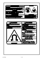
Page 23: ...62 11640 1 6 1 3 SAFETY DECALS ...
Page 24: ...1 7 62 11640 62 03958 ...
Page 25: ...62 11640 1 8 ...
Page 26: ...1 9 62 11640 ...
Page 27: ...62 11640 1 10 ...
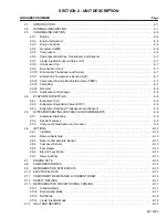
Page 125: ...62 11640 SECTION 6 MESSAGECENTER PARAGRAPH NUMBER Page 6 1 MESSAGECENTER MESSAGES 6 1 ...
Page 321: ......
Page 322: ......


