


T-372
4–26
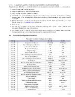
Note
: Configuration numbers not listed are not used in this application. These items may appear when loading configuration
software to the controller but changes will not be recognized by the controller programming.
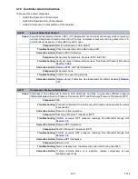
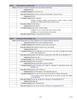
4.9 Controller Function Codes
CnF45
Low Humidity Enabled
Out
In
CnF46
Quench / Liquid Injection Valve Type
nO=0=no
nC=1=nc
CnF47
Vent Position
OFF
UP, LOW, CUStOM
CnF49
OEM Reset Option
OFF
0-off,1-std, 2-spec,3-cust
CnF50
Enhanced Bulb Mode Interface
0-out
1-in
CnF51
Timed Defrost Disable
0-out
1-in
CnF52
Oil Return Algorithm
0-out
1-in
CnF53
Water Cool Oil Return Logic
0-out
1-in
CnF55
TXV Boost Relay
0-out
1-in
CnF56
TXV Boost Circuit
0-out
1-in
CnF57
PWM Compressor Control
0-out
1-in
CnF59
Electronic Evaporator Expansion Valve
0-none
1-EC, 2-KE, 3-NA
CnF61
ACT ASC Control Enable
0-out
1-in
CnF62
Extended Temperature Control Enable
0-out
1-in
CnF63
QUEST Pre-Trip / TripWise Default State
0-on
1-off
CnF67
Air Heaters
0-out
1-in
CnF70
Enable XtendFRESH Logic
0-out
1-in
CnF71
XtendFRESH Pre-Trip / TripWise Default State
0-off
1-on
CnF74
TripWise Pre-Trip / TripWise Default State
0-off
1-on
CnF78
XtendFRESH Scrubber Output Available
0-out
1-in
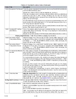
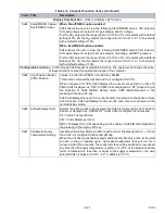
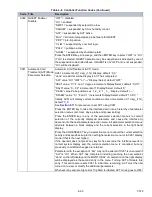
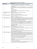
Table 4–8 Controller Function Codes
Code Title
Description
NOTICE
Note: If the function is not applicable, the display will read “-----”
Display Only Functions
- Cd01 through Cd26 are display only functions.
Cd01 Capacity Modulation
(%)
Displays the DUV percent closed. The right display reads 100% when the valve
is fully closed. The valve will usually be at 10% on start up of the unit except in
very high ambient temperatures.
Cd03 Compressor Motor
Current
The current sensor measures current draw in lines L1 & L2 by all of the high
voltage components. It also measures current draw in compressor motor leg T3.
The compressor leg T3 current is displayed.
Cd04
Cd05
Cd06
Line Current, Phase A
Line Current, Phase B
Line Current, Phase C
The current sensor measures current on two legs. The third unmeasured leg is
calculated based on a current algorithm. The current measured is used for
control and diagnostic purposes. For control processing, the highest of the Phase
A and B current values is used for current limiting purposes. For diagnostic
processing, the current draws are used to monitor component energization.
Whenever a heater or a motor is turned ON or OFF, the current draw increase/
reduction for that activity is measured. The current draw is then tested to
determine if it falls within the expected range of values for the component. Failure
of this test will result in a pre-trip failure or a control alarm indication.
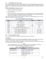
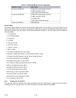
Table 4–7 Controller Configuration Variables (Continued)
Config
Title
Default
Option