


4–13
T-372
4.3.29
Protection Mode - Condenser Fan Override
When CnF17 (Discharge Temperature Sensor) is set to “In” and CnF48 (Condenser Fan Switch Override) is set to
“On”, the condenser fan switch override logic is activated. If condenser cooling water pressure is sufficient to open
the water pressure switch (de-energizing the condenser fan) when water flow or pressure conditions are not main
-
taining discharge temperature, the logic will energize the condenser fan as follows:
1. If the DUV is less than 80% open when the controller calls for it to be100% open, the condenser fan is ener
-
gized. When the DUV is 100% open, the fan will de-energize.
2. If DPT reading is invalid or out of range (AL65), the condenser fan is energized and will remain energized
until system power is cycled.
3. If the system is running on condenser fan override and the high pressure switch opens, the condenser fan is
energized and will remain energized until the system power is cycled.
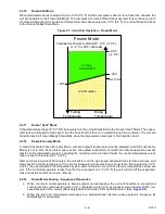
4.3.30
Quest
Quest (Quality and Energy Efficiency in Storage and Transport) power saving mode helps shipping lines lower their
operating costs by decreasing the system’s run time, energy usage and emissions. Quest is a method of tempera
-
ture control used during steady-state perishable cooling that cycles the compressor on and off according to supply
/ return air temperature conditions.
To be eligible for steady-state control, the unit must first complete a setpoint pulldown phase and a CCPC pulldown
phase:
• During setpoint pulldown, supply air temperature is controlled according to the unit’s nominal supply air setpoint.
• During CCPC pulldown, supply air temperature is lowered somewhat relative to the nominal setpoint. Evap
-
orator fans are forced to operate at high speed.
Steady-state CCPC control maintains the same lowered supply air temperature that was used during CCPC pull
-
down. The compressor cycles on and off according to return air high and low limits. Depending on the fan mode of
operation selected, the evaporator fans may be programmed to run at low speed some or all of the time according
to the control logic.
4.4 Controller Alarms
Alarm display is an independent controller software function. If an operating parameter is outside of expected
range or a component does not return the correct signals back to the controller, an alarm is generated. A listing of
.
The alarm philosophy balances the protection of the refrigeration unit and that of the refrigerated cargo. The action
taken when an error is detected always considers the survival of the cargo. Rechecks are made to confirm that an
error actually exists.
Some alarms requiring compressor shutdown have time delays before and after to try to keep the compressor on
line. An example is alarm code “LO,” (low main voltage), when a voltage drop of over 25% occurs, an indication is
given on the display, but the unit will continue to run.
When an Alarm Occurs:
• The red ALARM light illuminates for alarm code numbers 003, 017, 020, 021, 022, 023, 024, 025, 026, 027,
028 and 072.
• If a detectable problem exists, its alarm code will be alternately displayed with the setpoint on the left display.
• The user should scroll through the alarm list to determine what alarms exist or have existed. Alarms must be
diagnosed and corrected before the alarm list can be cleared.
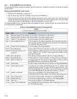
To Display Alarm Codes:
1. While in the default display mode, press the ALARM LIST key. This accesses the alarm list display mode,
which displays any alarms archived in the alarm queue.The alarm queue stores up to 64 alarms in the
sequence in which they occurred.
2. The user may scroll through the list by pressing an Arrow key. The left display will show “AL###,” where ##
is the alarm number sequentially in the queue. The right display will show the actual alarm code. “AA###”
will display for an active alarm, where “###” is the alarm code. Or “IA###” will display for an inactive alarm,
see
.
3. “END” is displayed to indicate the end of the alarm list if any alarms are active.