TRITON SYSTEMS, INC.
5-67
O
PERATION
M
ANUAL
- M
ODEL
97XX-Series
SECTION 5 - MANAGEMENT FUNCTIONS
9700-S
ERIES
9705-S
ERIES
9710-S
ERIES
9750-S
ERIES
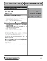
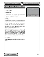
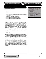
EXIT MESSAGE
F
ACTORY
D
EFAULT
: ‘T
HANKS
FOR
U
SING
MINI
ATM’
A
CCESS
I
NSTRUCTIONS
:
1.
Select TERMINAL CONFIGURATION from the MANAGEMENT
FUNCTIONS menu.
2.
Select CHANGE MESSAGES.
3.
Select EXIT MESSAGE.
D
ESCRIPTION
:
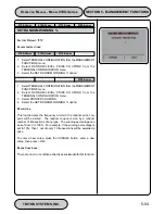
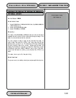
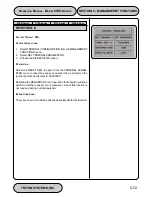
The Exit Message consists of three lines of text that are printed on
the terminal display at the conclusion of a transaction. Enter let-
ters, numbers and punctuation as described in the following para-
graphs.
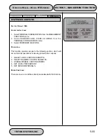
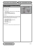
The keys along either side of the display are used with the numeric
keys on the main keypad to permit entry of alphanumeric charac-
ters. The keys on the left side of the display are designated <F1>
through <F4>. The keys on the right side of the display are <F6>
through <F8>. The <F1> key centers the text on the line where the
cursor appears. The <F2> key erases all text in the current mes-
sage. <F3> clears the text on the current line.
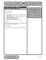
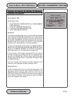
The <F4> Key is used similarly to a CAPS LOCK key on a com-
puter keyboard. Pressing the <F4> key toggles between upper-
case and lowercase. To enter an alphabetic or punctuation char-
acter, one of the <F6> through <F8> keys must be pressed, fol-
lowed by one of the numeric keys. The resultant character will be
as indicated in the table. Press the <OK> key to save the changes
made. If you make a mistake and want to start over, press the
CANCEL key to discard any changes made to that point.
E
RROR
C
ONDITIONS
:
There are no error conditions directly associated with this function.
Y
E
K
4
F
R
E
P
P
U
1
2
3
4
5
6
7
8
9
0
t
f
i
h
S
o
N
1
2
3
4
5
6
7
8
9
0
t
f
e
L
6
F
Q
A
D
G
J
M
P
T
W
,
r
e
t
n
e
C
7
F
Z
B
E
H
K
N
R
U
X
.
t
h
g
i
R
8
F
p
S
C
F
I
L
O
S
V
Y
-
4
F
R
E
W
O
L
t
f
i
h
S
o
N
!
@
#
$
%
^
&
*
(
)
t
f
e
L
6
F
q
a
d
g
j
m
p
t
w
’
r
e
t
n
e
C
7
F
z
b
c
h
k
n
r
u
x
+
t
h
g
i
R
8
F
&
c
f
i
l
o
s
v
y
=
Summary of Contents for Triton 9700
Page 1: ...Owner s manual Triton Owner s Manual 9700...
Page 12: ...SECTION 1 INTRODUCTION...
Page 22: ...SECTION 2 BASIC OPERATION...
Page 28: ...SECTION 3 INITIAL SETUP...
Page 36: ...SECTION 4 CURRENCY HANDLING...
Page 55: ......
Page 56: ...SECTION 5 MANAGEMENT FUNCTIONS...
Page 213: ......
Page 214: ...SECTION 6 MAINTENANCE...
Page 220: ...SECTION 7 JOURNAL ENTRIES...
Page 223: ......
Page 224: ...SECTION 8 ERROR RECOVERY...
Page 246: ...SECTION 9 CUSTOMER TRANSACTIONS...
Page 251: ......
Page 252: ...APPENDIX A MECHANICAL LOCK...
Page 255: ......
Page 256: ...APPENDIX B ELECTRONIC LOCK...
Page 259: ......
Page 260: ...APPENDIX C WARRANTY POLICY...

