


Page 16
E
XTERNAL CONNECTIONS
M
motor
T1
transformer
V1
RPM sensor
S22 reference point switch
T
photocell transmitter
R
photocell receiver
S3
push button
IMPULSE
S4
push button
STOP
X1
plug 1~N 220-240V 50Hz
X3A flat cable connector dc motor
X2C ground
X2A and X2B = 24V
X6
Relay output contact 1
H4
Operator light
H5
signal light
1
internal relay (optional)
2
external relay (optional)
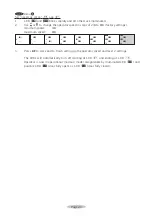
W20 Receiver HF module output
24V 24 VDC, 50mA max.
0V
masse (ground)
RC
Contact
bk
black
bn
brown
or
orange
rd
red
gr
green
bl
blue
ye
yellow
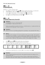
Wall control (push button impulse):
It is possible to either connect a push button or
a 3-function wall console with impulse, light
on/off and an electronic vacation lock functions.
When operator LED 4 burns and LED 3 flashes
the 'vacation' lock is actiated.
De-activate 'vacation' lock on 3-function wall
console or by briefly pressing
%
button on
operator.