14
docs.carbide3d.com
15
Attach the Adjustable
Leveling Feet
1.
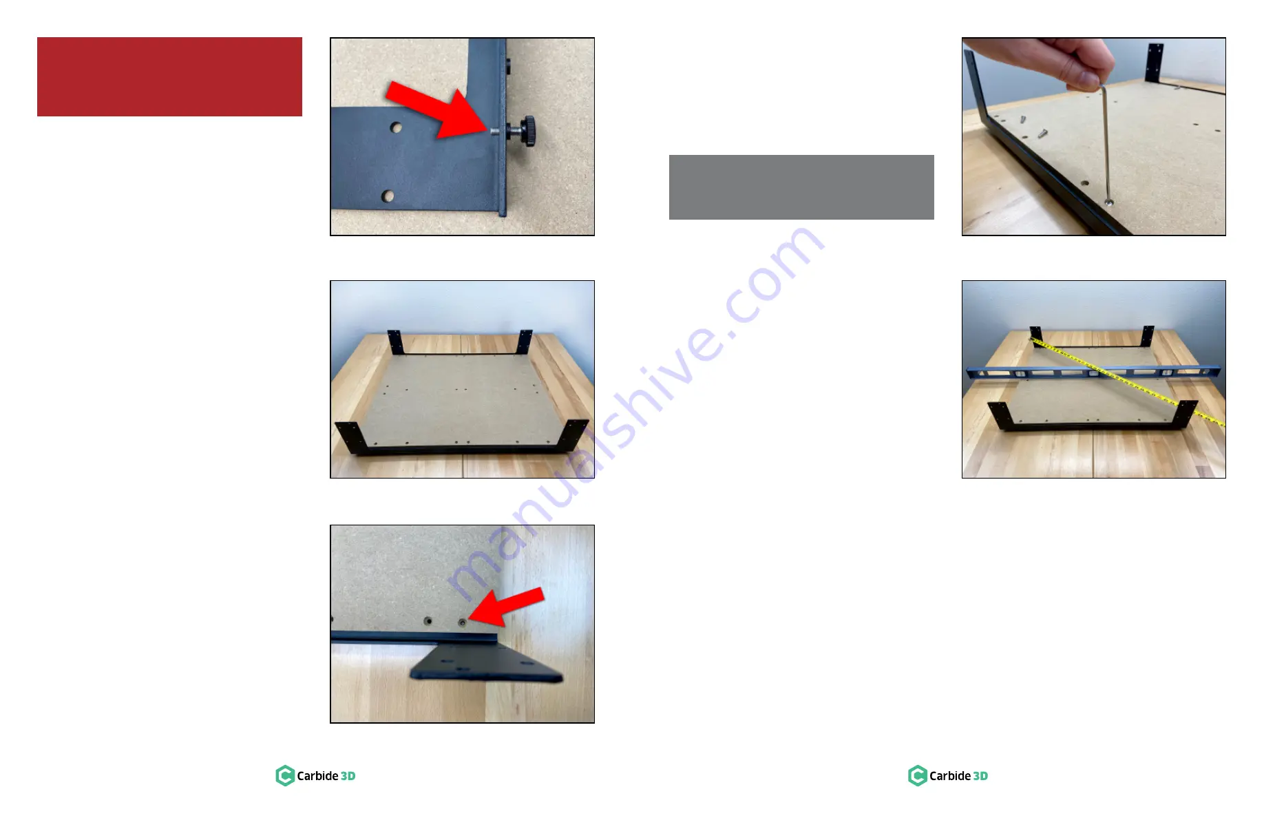
Screw the four (4) adjustable leveling feet
into the outermost PEM nuts at either end of
each endplate. Screw in until there is an equal
portion of thread exposed above and below
the endplate, about 3/16
″
.
See
Figure 2‑4
.
Attach the MDF Baseplate
to Front and Rear
Endplates
1.
Position the MDF baseplate on your
workspace with the countersunk holes facing
up and the longer sides toward the front and
rear. See
Figure 2‑5
.
2.
Slide both endplates, leveling feet down,
into place along the front and rear edges of
the baseplate. The protruding threads of the
leveling feet will insert into the outermost
screw holes from the underside of the
baseplate. See
Figure 2‑5
and
2‑6
.
3.
Use the 3mm hex key and twelve (12)
M5
×
25mm button head cap screws to secure
the MDF baseplate to the two endplates, six
(6) screws for each endplate. See
Figure 2‑7
.
4. Turn the screws until they stop but do not fully
tighten.
Level the Baseframe
Assembly
1.
Adjust the height of each leveling foot to bring
the fully assembled baseframe into level.
Check level front-to-back, side-to-side, and
diagonally. See
Figure 2‑8
.
2.
Optionally, you can check for square by
measuring diagonally across the baseframe
from the outside edges of the endplates. Check
both sides. The machine is square when the
two measurements are equal. Approximates
are acceptable at this stage as the machine is
not fully tightened. A final level and square is
completed in
Step 9: Level and Square
.
NOTE:
We’ll come back and tighten all of the
baseframe screws later on when squaring
the machine.
WARNING:
Do not assemble the Shapeoko
3 on the floor; a large workbench is essential.
The completed dimensions of the Shapeoko 3
are 28.5
″
(X)
×
24
″
(Y)
×
17.5
″
(Z).
Figure 2-5
Figure 2-6
Figure 2-7
Figure 2-4
Figure 2-8


