


TM
Operation
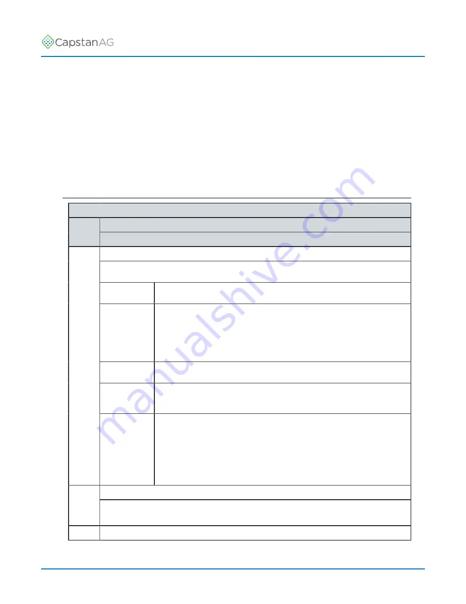
Flow Settings Menu Descriptions
Flowmeter Setup
Line Title
Line
Number
Description
Meter 1 Type
Type of flowmeter used on your machine.
Transparent The flow signal from the flowmeter will be used without any adjustment.
Correction At flows above the minimum, the signal from the flowmeter is used, but
adjusted with calculations for turn compensation and individual nozzle
shutoff.
At flows below the minimum, the value is calculated.
Calculation All flow is calculated, the flowmeter is not used.
NH3
Calculation
All flow is calculated, the flowmeter is not used. The calculations are
corrected for the properties of NH3.
1
NH3
Correction
At flows above the minimum, the signal from the flowmeter is used, but
adjusted with calculations for turn compensation and individual nozzle
shutoff.
At flows below the minimum, the value is calculated.
The calculations are corrected for the properties of NH3.
Meter 1 Minimum
2
The flowmeter minimum value is the minimum flow at which the flowmeter is accurate.
3
Meter 1 Calibration
©
2021 Capstan Ag Systems, Inc.
46
PinPoint
™
III ENVELOP
Summary of Contents for PinPoint III ENVELOP
Page 6: ......
Page 65: ...TM Operation 2021 Capstan Ag Systems Inc 65 PinPoint III ENVELOP...
Page 66: ...TM Operation Nozzle Spacing 50 cm 2021 Capstan Ag Systems Inc 66 PinPoint III ENVELOP...
Page 67: ...TM Operation 2021 Capstan Ag Systems Inc 67 PinPoint III ENVELOP...
Page 69: ...TM Operation 2021 Capstan Ag Systems Inc 69 PinPoint III ENVELOP...
Page 71: ...TM Operation 2021 Capstan Ag Systems Inc 71 PinPoint III ENVELOP...
Page 72: ...TM Operation Nozzle Spacing 20 in 2021 Capstan Ag Systems Inc 72 PinPoint III ENVELOP...
Page 73: ...TM Operation 2021 Capstan Ag Systems Inc 73 PinPoint III ENVELOP...
Page 75: ...TM Operation 2021 Capstan Ag Systems Inc 75 PinPoint III ENVELOP...
Page 76: ...TM Operation 2021 Capstan Ag Systems Inc 76 PinPoint III ENVELOP...
Page 84: ...TM Maintenance 2021 Capstan Ag Systems Inc 84 PinPoint III ENVELOP...
Page 116: ...TM Troubleshooting 2021 Capstan Ag Systems Inc 116 PinPoint III ENVELOP...
Page 122: ...TM Schematics System Layout Figure 42 2021 Capstan Ag Systems Inc 122 PinPoint III ENVELOP...
Page 124: ...TM Schematics 2021 Capstan Ag Systems Inc 124 PinPoint III ENVELOP...
Page 127: ......


