background image

Troubleshooting

-64-

6

Area

Malfunction

Possible Cause

Corrective Measure

Ref.

Cutting 
System

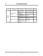
Cutting blade cuts into 
ground.

Cutting height is too 
low.

→Raise cutting height.

Work site has 
undulations.

→Raise cutting height.

Cutting blade (knives 
or stay) is bent.

→Replace.

Cutter load is too high.

Engine speed is too low. →Raise engine speed.
Driving speed is too 
high.

→Drive slow.

Cut grass or vines 
are tangled to cutting 
blade axle.

→Untangle.

Summary of Contents for CM141

Page 1: ...njury or death Keep this manual for future reference by you and by all those who operate and maintain this machine CHIKUSUI CANYCOM INC 90 1 Fukumasu Yoshii machi Ukiha shi Fukuoka Japan 839 1396 Tel 81 0 943 75 2195 Fax 81 0 943 75 4396 Original Instructions in English Ride on Brushcutter CM141 CM142 Operator s Manual 5343 5204 001 01 ...

Page 2: ...uarters TEL 81 0 943 75 2195 FAX 81 0 943 75 4396 Foreign Trade Center TEL 81 0 3 3552 6277 FAX 81 0 3 3552 6288 All rights reserved Unauthorized use or reproduction of this material is prohibited Authorized Dealer CHIKUSUI CANYCOM INC ...

Page 3: ...ngerous This machine may not be operated on public road or what is considered to be public road It is the sole responsibility of the operator to consult the local regulations Do not modify this machine or do not operate this machine with the safety covers removed or open A serious accident could result Thank you for purchasing this machine This manual provides information needed for safe and effec...

Page 4: ...to the machine if the user does not follow the procedures or the instructions Indicates important information which needs particular attention In this manual the following four warning terms are used to signal the four levels of hazard or seriousness of possible accidents Read and understand what they mean and always follow the instructions in this manual Warning Terms Used in this Manual NOTE Not...

Page 5: ...ke sure to have the product name serial number and the make and type of engine handy at the time of contact The model and serial number can be found on the model label as shown below and the make and type of the engine can be found in Chapter 3 Specifications of this manual Page13 After Sales Service Location of Model Label Model Label The replacement or repair parts for this product shall remain ...

Page 6: ...n 5 Operation 6 Servicing 10 2 Controls and Components 11 Name and Function of Controls 11 3 Specifications 13 Product Specifications 13 Contents of Tool Bag 14 Optional Attachment 14 4 Operation 15 Preparation 15 Pre start up Inspection 15 Checking and Filling Fuel 15 Adjusting Seating Position 16 ...

Page 7: ... Cutting Height 26 Cutting 27 5 Maintenance 31 Maintenance Schedule 31 Engine 31 Chassis 32 List of Fluids and Lubricants 34 Greasing Points 35 List of Consumables and Spares 36 Removing and Installing Body Panels 38 Front Cover 38 Rear Covers 39 Upper Rear Cover 39 Floor Panel 40 Cutting Blade Shield 40 Engine 41 Engine Oil 41 Air Cleaner 43 Spark Plugs 43 ...

Page 8: ...e Belt 47 Parking Brake 48 Cutting System 49 Cutting Blades 49 Cutting Rotary Drive Belt 52 Cutting Rotary Brake 53 Electrical System 55 Battery 55 Fuse 57 After Use Care 58 Cutting System 58 After Normal Use 59 After Cold Weather Use 60 Storage 61 6 Troubleshooting 62 Troubleshooting 62 ...

Page 9: ... after you have received and fully understood the instructions for handling this machine and received the receipt Appendix Operator s Manual for the Engine Be sure to read and understand it together with this manual 7 Transporting 67 Hauling 67 Loading and Unloading 67 Hoisting 68 Manual Transfer Lever 69 ...

Page 10: ... instructions and precautions in them Failure to do so could result in serious injury or death to the operator or bystanders Keep the labels clean and legible Do not use solvents or gasoline to clean the labels Replace these labels immediately if they have been removed have fallen off or become illegible Use the part number on the label or shown in this manual to order a replacement label from you...

Page 11: ...t 3 Après utilisation bien nettoyer le couvercle du moteur avec de l air pulsé afin d extraire l herbe seche Um die Gefahr von Feuer zu vermeiden 1 Betanken Sie das Gerät erst nachdem Motor und Auspuff abgekühlt sind Füllen Sie den Tank bis zum oberen Limit 2 Falls Sie die Maschine an steilem Gelände betreiben stellen Sie sicher daß sich immer genügend Benzin im Tank befindet und füllen Sie falls ...

Page 12: ... the machine Never allow people unfamiliar with these instructions to operate or service the machine Do not let anyone under 18 years of age to operate this machine Local regulations may restrict the minimum age for operating the machine Consult your local authority The operator is responsible for the accidents or hazards caused to other people or their property This machine has a riding capacity ...

Page 13: ...es will reduce the risk of accidents Never handle fuel or grease service the engine or recharge the battery in the presence of fire or spark Perform the daily pre startup inspection see Preparation pages 15 before starting the machine Repair or replace damaged parts before starting the machine Preparation Operation This machine is intended for cutting grass and bushes Any other use may pose hazard...

Page 14: ... exercise caution to reduce the chance of skidding or sliding out of control Never operate on ice Always make certain that there is no obstacle or a person behind the machine when backing up After confirming that it is safe to back up move slowly and avoid sharp turns To reduce the risk of tip over pay special attention when encountering an obstacle or a slope or when braking on a slope or during ...

Page 15: ...d a slope that is so rough slippery or loose that you feel like you could tip over When driving up a slope proceed at a steady rate of speed and throttle position Never move the throttle lever the drive lever or the steering wheel suddenly If the engine stalls or loses traction during a climb and cannot make it to the top of the slope do not try to turn the machine around Carefully back down slowl...

Page 16: ...ople especially children off the work site Pay attention to the surrounding area Rotating cutting blade throws stones rocks and debris This may cause property damage injury or death Always cut grass with cutting blade shield closed to prevent objects from being thrown out Drive forward when cutting This best prevents the cutting blades from throwing stones rocks or debris Pay attention to obstacle...

Page 17: ...hten or repair them as needed If the engine must be running to perform a service keep hands feet clothing and any part of the body away from any moving part especially the cooling fan and the belts at the side of the engine Do not touch the engine muffler or exhaust pipe while the engine is running or soon after it has stopped These areas will be very hot and can cause burns The engine must be shu...

Page 18: ...trols and Components 2 Name and Function of Controls Forward Steering Wheel Cutting Blade Shield Rear Cover Front Cover 5331M 0201 011E Seat Fuel Filler Cap Rear Tire Front Tire 2 3 4 5 9 8 7 1 6 10 Fuel Cock ...

Page 19: ...pedal is depressed drive lever returns to neutral position and brake is engaged 6 Parking Brake Lock Parking brake lock lever is used when parking machine securely Pulling parking lock lever while brake pedal is depressed locks brake pedal 7 Cutting Height Adjust Cutting height adjust lever is used to adjust the cutting height There are 5 steps on CM141 and any height between 0 and 80mm without st...

Page 20: ...n EX40DS Type Air cooled 4 cycle single cylinder OHC Gasoline Cylinder Bore Stroke mm 89X65 Displacement cm3 404 Maximum Output kw PS rpm 10 3 14 3600 Maximum Torque N m kgf m rpm 27 2 7 Starter System Electric Recoil Fuel Automotive Unleaded Gasoline Fuel Consumption g kW h g PS h 400 297 Fuel Tank Capacity L 15 5 Ignition Contactless Magneto Spark Plug NGK BR6HS Electrical Battery Type 40B19R Ba...

Page 21: ...stepless Blade Type Free Knife Stepped Stay Number of Blades 2 Blade Drive Train Shaft Drive These specifications are subject to change without notice No Content Quantitiy Note 1 Operator s Manual 1 This Manual 2 Operator s Manual for the Engine 1 3 Engine Service Tool 1 for Servicing Engine 4 Plate 1 for pushing 5 Quick Reference Guide 1 6 Key 2 for Rear Cover Contents of Tool Bag Option Type Pro...

Page 22: ...le page 31 for the inspection schedule and procedure Checking and Filling Fuel 1 Check fuel gauge If fuel level is low fill fuel 2 Open fuel filler cap and fill fuel 3 Put fuel filler cap back in place and close it securely 5331M 0401 010E Fuel Gauge Fuel Filler Cap Fuel Automotive Unleaded Gasoline Fuel Tank Capacity 7 0L NOTE Always perform a pre startup inspection If machine needs repair servic...

Page 23: ...at try moving seat back and forth and up and down to make sure it is securely locked in its position Adjusting Seating Position 5331M 0401 020E Seat 5331M 0401 030E Bolts 1 Lift seat up 2 Loosen bolts and slide seat forward or backward to adjust 3 Tighten bolts firmly after adjusting seat ...

Page 24: ...ture ranges Using this machine under such conditions may result in an accident or cause damage to machine In the winter or cold climate warm up engine thoroughly before driving machine A cold engine delivers poor performance which may result in an accident It also causes excessive wear Do not use this machine in dusty places such as desert Dust may clog air cleaner or enter engine which may reslt ...

Page 25: ...ral position Drive lever returns to neutral when brake pedal is fully depressed NOTE Safety feature engine cannot be started unless brake pedal is depressed NOTE Safety feature engine cannot be started unless cutting rotary clutch lever is in OFF position NOTE 5331M 0402 141E Fuel Cock Open 1 Open fuel cock 5331M 0402 010E Brake Pedal Parking Brake Lever 5331M 0402 020E Cutting Rotary Clutch Lever...

Page 26: ...position Avoid frequent starting Once engine starts run it for a while to charge battery NOTE 6 Move choke lever to Close position 5 Move throttle lever slightly toward HI fast position 9 Move throttle lever to LO slow position HI Throttle Lever 53314M 0402 040E LO 5331M 0402 151E Choke Knob Close Main Switch 5331M 0402 050E ON Start OFF 53314M 0402 060E Throttle Lever HI LO ...

Page 27: ...ut 2 minutes to warm up Do not allow bystanders to come near machine when driving Always make certain of the safety of your surroundings before driving start slow Always make certain of the safety of your surroundings before turning Do not make sudden starts acceralation change of speed change of direction or stop Do not turn at speed Avoid sudden maneuvers this may cause the operator to fall or t...

Page 28: ... pedal lock 1 M a k e c e r t a i n o f t h e s a f e t y o f y o u r surroundings 2 Move the throttle lever toward HI fast position to increase engine speed 53314M 0402 170E Throttle Lever HI LO 5331M 0402 070E Brake Pedal Parking Brake Lever 5331M 0402 081E Drive Lever 5331M 0402 090E Steering Wheel Speed can be adjusted continuously by the position of drive lever NOTE ...

Page 29: ...ion other than neutral and depress brake pedal simultaneously HST may be damaged 5331M 0402 031E Drive Lever 5331M 0402 100E Brake Pedal 1 Gradually return drive lever to neutral to slow down 2 Release hand off drive lever 3 Depress brake pedal to stop machine completely When brake pedal is depressed drive lever returns to neutral NOTE ...

Page 30: ...ition under normal running condition Differential may be damaged Do not turn machine when differential lock is in ON position 1 Move differential lock lever to ON position 2 Drive slowly out of the slippery area Differential can be locked to minimize slipping on slippery surface 3 Once machine is out of the slippery area stop and move differential lock lever to OFF position 5331M 0402 110E Diff Lo...

Page 31: ...or steeper If it is absolutely necessary to park machine on a slope less than 10 degrees make certain to apply parking brake firmly and block wheels with chocks Do not park near flammables Always apply parking brake and remove key from main switch when parking Parking 3 Depress brake pedal and pull brake lock lever to lock brake pedal in depressed position 53314M 0402 060E Throttle Lever HI LO 533...

Page 32: ... 23 Operation 4 4 Turn main switch to off to stop engine Remove ignition key 5331M 0402 131E ON OFF Main Switch ...

Page 33: ...ly actual cutting height may vary due to the condition of ground or brush and other factors NOTE Cutting Height Adjust Lever Position Indication of Cutting Height Transport For Transport 5 65 mm 4 50 mm 3 35 mm 2 20 mm 1 0 mm 5331M 0403 010E Cutting Height Adjust Lever Adjusting Cutting Height CM141 5343M 0403 010E Cutting Height Adjust Lever Lock Lever Adjusting Cutting Height CM142 1 Pull lock l...

Page 34: ...s intended to cut brush while moving forward and this best prevents stones and debris from being thrown Turn cutting rotary clutch to ON only when cutting Keep it in OFF position all the other times Never attempt to cut brush on the edge of a ditch or bank Shoulder of the ditch or bank may collapse Pay special attention after heavy rain or earthquake Inspect the work site beforehand inspect terrai...

Page 35: ...ken replace it and the other blade with a new pair A broken blade causes excessive vibration which damages machine When something is tangled to cutting blade stop engine immediately and remove the tangled object Such object causes excessive vibration which damages machine 1 Make sure cutting blade shields on both sides are closed 5321M 0403 060E Cutting Blade Shield 2 Turn throttle lever to Hi fas...

Page 36: ...M 0403 030E Cutting Rotary Clutch Lever 5 Drive machine forward to cut When cutting with this machine for the first time start on a flat surface Drive slowly and in an overlapping pattern If load to cutting blade is high drive slowly or cut twice Safety feature engine stops automatically if operator leaves seat while cutting blade is rotating NOTE 5331M 0403 051E Drive Lever ...

Page 37: ... to OFF to stop cutting blade 7 Move cutting height adjust lever to Transport Moving cutting rotary clutch lever to OFF applies brake on cutting blade to stop NOTE 5331M 0402 020E Cutting Rotary Clutch Lever 5331M 0403 040E Cutting Height Adjust Lever ...

Page 38: ...appets Every 300 hours do more frequently in dusty place Remove carbon deposit from cylinder head Every 500 hours do more frequently in dusty place Clean carburator Every 500 hours clean more frequently in dusty place Perform valve lapping Every 500 hours clean more frequently in dusty place Replace fuel hose Every two years Overhaul 1000 hours contact Canycom representative for overhaul Engine Oi...

Page 39: ...e observed Transmission Irregular noise or overheating shall not be observed when moving forward or backward There shall not be oil leaks in or around transmission HST HST shall perform normally Hydraulic fluid shall be filled to a proper level and shall be clean and free of dirt or contamination Page 46 Lever shall not be loose or have excessive play V belt Belt tension shall be properly adjusted...

Page 40: ... or damage Page 49 Blade mounting pins and stay shall be free of cracks or damage Page 49 Cutting blade shield shall be free of cracks or damage Skirt on cutting blade shield shall be free of cracks or damage and shall not be missing Belt tension shall be properly adjusted Page 52 Belt shall be free of damage or excessive wear Page 52 When activated cutting blade brake shall stop cutting Rotary Pa...

Page 41: ... SAE rating 10W 30 1 2L Transmission Oil Change Initially After 50 hours of use Every 500 hours afterwards Gear Oil API rating GL 4 or 5 SAE rating 80 1 4L HST Fluid As needed Gasoline Engine Oil API rating SE or better SAE rating 20W 50 1 1L Cutting Rotary Grearbox Oil As needed Gear Oil API rating GL 4 or 5 SAE rating 80 0 25L Battery Electrolyte Fill Inspect every 50 hours and fill when necessa...

Page 42: ...ry 6 Months Chassis Grease 4 Cutting rotary link pivots Every 6 Months Chassis Grease Grease regularly Insufficient greasing may result in seizure or rusting affecting smooth operation of machine When using a manual grease pump push handle five to six times When handle becomes heavy stop pushing When using a pneumatic grease pump charge for two to three seconds NOTE 5331M 0503 010E Greasing Points...

Page 43: ...543000 Replace if defective 2 Brake Lining Set 73069901000 Replace if defective Replace in pairs 1 Wire Brake 53313305000 Replace if defective 1 Wire Differential Lock 1 53313402000 Replace if defective 1 Cooling Fan 73061137000 Replace if defective 1 Cutting System Blade Set Iai Z3214206010 Replace if defective 1 Pin for Blade 2 53314208000 Replace if defective 2 Wave Washer 2 53314207000 Replace...

Page 44: ...ce 5 1 Differential Lock Model 2 Included within set of blades Iai Item Part No Schedule Qty Electrical System Battery 40B19R 37053901000 Replace if defective 1 Fuse 15A Green Main 09801003002 Replace if defective 1 ...

Page 45: ...azard exists when removing or installing body panels beware of sharp edges and pinch points Make certain to reinstall panels after removing for repairs or inspection 2 Remove front cover Always stop engine and remove key when removing body panels 5331M 0505 010E Knob Bolt 5331M 0505 020E Front Cover ...

Page 46: ... key from lock Check if cover is locked firmly by pressing cover handle Rear Cover 3 Rear cover panel can be removed by sliding toward right when it is open 1 Remove 4 bolts 2 Remove upper rear cover Upper Rear Cover 5331M 0505 030E Cover Handle Lock Rear Cover 5331M 0505 070E Rear Cover Hinge Hinge 5331M 0505 050E Bolts Upper Rear Cover ...

Page 47: ...de shield 2 Tighten knob bolt and fix blade shield firmly 5331M 0505 060E Bolts Bolts right and left Floor Panel 5331M 0505 040E Knob Bolt Blade Sheild Blade shield can not fully opened when cutting height adjust lever is in Transport position Set cutting height adjust lever to 3 or lower to fully open the blade sheild NOTE ...

Page 48: ... Insert oil filler cap and pull it out Make certain to fill engine with correct grade of oil to the specified level Insufficient amount or wrong grade of oil reduces performance and may cause permanent damage to engine Dispose of the drained oil properly Inspecting To obtain correct reading check oil level before starting or wait about 10 minutes after stopping engine to allow oil to drain back to...

Page 49: ...level is between upper and lower limits 4 Put oil filler cap back in place Changing 1 Have an appropriate oil drain pan 2 Open rear cover and place oil drain pan under the guide plate 3 Remove oil filler cap 3430M 0505 020E Lower Limit Upper Limit 5331M 0506 010E Oil Filler Cap 5331M 0506 050E Guide Plate 5331M 0506 021E Drain Plug 4 Remove drain plug and drain oil 5 Put drain plug back in place 6...

Page 50: ...Spark Plugs 1 Remove spark plug cap 2 Remove spark plug with contained Engine Tool or appropriate plug wrench 3 Follow the instructions in Operator s Manual for the engine to inspect clean or change spark plugs 4 Put spark plug back in place 5 Put spark plug cap back in place Never pull ignition cable when removing a spark plug cap Conductor in the cable may be severed or damaged If a spark plug i...

Page 51: ...1 Park machine on a level ground 2 Remove valve cap 3 Check tire air pressure If different from the specified values adjust pressure 4 Put valve cap back in place 5319M 0508 010E Valve Cap Inflate tires to the specified pressure Under or over inflation causes uneven wear or other damages to tires Tire Size Pressure KPa kgf cm2 Front Wheel AGR 3 50 7 2PR 110 1 1 Rear Wheel 16 7 00 8 2PR 130 1 3 Dis...

Page 52: ...o Use Page 34 Oil Capacity Page 34 NOTE 5331M 0507 010E Oil Level Gauge Lower Limit Standard Level Upper Limit 1 Park machine on a level ground 2 Have an appropriate oil drain pan 3 Open rear cover 4 Remove oil plug 5 Remove drain plug and drain oil 6 Put drain plug back in place 7 Fill specified amount of correct oil into filler 8 Put filler cap back in place 9 Close rear cover 5331M 0507 020E Dr...

Page 53: ...efore starting or wait until HST fluid cools off sufficiently Hot HST fluid expands in volume and does not provide correct reading It is enough if oil level is on MIN when oil is sufficiently cool Do not fill fluid more than MAX level Fuluid may expand and overflow from the tank Oil to Use Page 34 Oil Capacity Page 34 NOTE 1 Open rear cover and remove upper rear cover 2 Remove HST fluid filler cap...

Page 54: ...ut of this range adjust spring with adjust nut 3 Visually inspect belt Replace belt if it is damaged For replacement contact your CANYCOM representative 4 Install upper rear cover back in place Adjust belt tension properly Inproperly tensioned belt may reduce performance and its service life Adjust Nut Lock Nut Spring 5331M 0507 040E A V Belt A 5331M 0507 070E ...

Page 55: ...ted brakes may result in property damage serious injury or death Parking Brake 1 Lock brake pedal with parking brake lock lever 2 Remove floor panel 3 Inspect that the strech of spring is 3mm If it is not adjust it with adjust nut Brake 5331M 0507 050E Spring Adjust Nut 5331M 0507 060E ...

Page 56: ...ve ignition key when servicing Allow machine to cool off before servicing Engine and its ancillaries are very hot after operation and may pose a burn hazard When a blade is damaged replace it and the other blade immediately Always replace blades in pair Damage due to vibration may occur When replacing blades replace pins for blades and wave washers with new ones Blades may be thrown out due to wor...

Page 57: ...r replacement of rotor stay NOTE 1 Open cutting blade shield 2 Visually inspect blades and pin for wear and damage If blades are worn normaly turn them over and use Replace if both edges are worn If blades or pin are worn excessively deformed damged or missing replace them with new components Inspecting A B 5331M 0508 010E New Wear Limit Blade Pin Replace when either of the part wears out 5331M 05...

Page 58: ...nting Slot Flat Faces 3 Install new mounting pin to blade and shift blade along mounting slot noting the direction of the flat faces 5331M 0508 060E Blade Mounting Pin Always put thick gloves on and be cautious when handling blade because both edges of rotor stay can get sharp by wear Wear Limit See page 50 If it is difficult to remove blade wash page 58 NOTE Replacing ...

Page 59: ...y Drive Belt Adjust belt tension properly Inproperly tensioned belt may reduce performance and its service life 1 Open rear cover 2 Move cutting height adjust lever to 5 position on CM141 or 80 on CM142 3 Move cutting rotary clutch lever to ON 4 Check V belt tension Inspect that the length A of spring is within the range of 112 mm to 113mm If it is out of this range adjust spring with adjust nut 5...

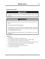
Page 60: ...rties or persons Inspect cutting brotary brake whenever the performance of it seems inadequate Inspecting 1 Start engine 2 Turn throttle lever to HI fast to raise engine speed 3 Move cutting height adjust lever to 5 position on CM141 or 80 on CM142 4 Turn cutting rotary clutch lever to ON to rotate cutting blade 5 Move cutting rotary clutch lever to OFF to observe if cutting blade stops within 5 s...

Page 61: ...o that it is approximately 5mm when clutch lever is in OFF position 4 Install upper rear cover rear cover back in place 5 Check if cutting blade stops within 5 seconds again If it does not consult with your CANYCOM representative Adjustting 5331M 0509 040E Turn Buckle Spring C B 5323M 0509 040E C ...

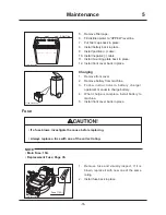
Page 62: ...drogen gas generated during charging is extremely explosive Always remove battery from machine before charging Failure to do so causes damage to electrical components and wiring Always disconnect terminal first and connect terminal first Disconnecting or connecting in the opposite order may cause a short circuit When installing battery make certain to connect and terminals to their original positi...

Page 63: ...d beyond UPPER level line Battery fluid may spill and cause damage to machine or injury to person Follow battery charger user s manual when charging Filling 5331M 0509 010E Battery 5331M 0509 050E UPPER LOWER 5331M 0509 020E Negative Terminal Positive Terminal Mounting Plate 3 Visually inspect that battery fluid level is between UPPER level and LOWER level lines 4 If fluid level is near or below L...

Page 64: ...E 5 Remove filler caps 6 Fill distilled water to UPPER level line 7 Put filler caps back in place 8 Install battery back in place 9 Install positive cable 10 Install negative cable 11 Install mounting plate back in place 12 Install front cover back in place 1 Remove front cover 2 Remove battery from machine 3 Follow instructions in battery charger operator s manual to charge battery 4 When charge ...

Page 65: ...cutting blade is rotating Do not allow bystanders to come near machine when cutting blade is rotating Always ride on machine when rotating cutting blade Never attempt to rotate cutting blade with cutting blade shield open Stones or rocks can be thrown and cause damage to surrounding properties or persons Turn cutting rotary clutch to ON only when cleaning Keep it in OFF position all the other time...

Page 66: ...vering after it is cooled off Do not wash engine or control panel with running water water may enter inside and cause rust or damage Fire hazard clean machine of cut grass and similar material after use Cut grass that is accumulated on the machine can catch fire Do not set cutting height too low It may hit ground Work on level ground without any stones Use hose with 15mm or 18mm of inner diameter ...

Page 67: ...inoperable due to freezing 1 Clean machine wash off dirt mud and remove grass and other foreign materials after use 2 Park machine on a paved or firm dry surface or on a bed of lumber 3 If machine is to be left outside cover machine with protective water proof covering after it is cooled off After Cold Weather Use Fire hazard clean machine of cut grass and similar material after use Cut grass that...

Page 68: ... humid dusty or hot place Fire hazard do not store machine where there is a possiblity of ignition Battery dischages even when it is not in use A battery may hold charge for a few months but it is a good practice to charge battery before it goes flat it will extend battery life Refer to Operation Manual for the engine for detailed instructions on preparing engine for storage NOTE 7 Turn fuel cock ...

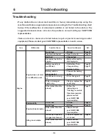
Page 69: ...fuel cock Page 18 Bad fuel Change fuel Excessive fuel in the engine Wait a while and try starting again Battery capacity is insufficient Add battery fluid Charge battery Replace battery Page 56 Page 57 Battery cable is disconnected Connect the battery cable Insufficient or wrong oil Fill or change oil Page 41 Dirty or damaged spark plug Clean or replace the spark plug Page 43 Other other than the ...

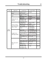
Page 70: ...entative Engine overheats Insufficient amount of engine oil Fill oil Page 41 Rotating screen or cooling fins are clogged or blocked Clean Excessive fuel consumption Clogged air cleaner Clean or replace the air cleaner Page 43 Other other than the above Please contact your CANYCOM representative Black smoke comes out of exhaust Choke is not fully open Open the choke fully Clogged air cleaner Clean ...

Page 71: ...achine does not turn smoothly Tires are not properly inflated Adjust tire pressure Page 44 Other other than the above Please contact your CANYCOM representative Machine does not run straight Tie rod is not properly adjusted Please contact your CANYCOM representative Brake Brake or parking brake does not work well or machine pulls to one side when braked Brake is not proerly adjusted Adjust Page 48...

Page 72: ...st Replace cutting blades Page 49 Foreign object is caught by cutting blade Remove or clean foreign object Other other than the above Please contact your CANYCOM representative Cut grass is not discharged properly Grass is wet Cut when grass is dry Grass is too long Cut in several steps at different heights Cutting height is too low Raise cutting height Engine speed is too low Raise engine speed D...

Page 73: ...to ground Cutting height is too low Raise cutting height Work site has undulations Raise cutting height Cutting blade knives or stay is bent Replace Cutter load is too high Engine speed is too low Raise engine speed Driving speed is too high Drive slow Cut grass or vines are tangled to cutting blade axle Untangle ...

Page 74: ...ve anti slip ramp surfaces Secure the hooks of loading ramps firmly and flush with loading deck Move slowly forward when loading onto and move slowly backward when unloading off of transporter Pay special care when going over the joint between loading deck and ramps machine may tip Do not turn on loading ramps Machine may fall Tie down machine securely Make sure machine does not move around Haulin...

Page 75: ...s of the same length when more than one is used Pay special attention to the center of gravitiy and the balance of machine when hoisting 3 Turn throttle lever to Low set cutting height adjuster lever to Transport and drive machine slowly forward onto loading deck 4 Park machine according to the instructions in Parking Page 24 Tie tmachine with rope or tie down belts and secure it onto loading deck...

Page 76: ...and the other to operate manual transfer lever Never push machine on a slope because it is dangerous 5331M 0703 010E Manual Transfer Lever 5331M 0703 020E Plate Transmission Mount Plate 1 Remove rear cover 2 Pull manual transfer lever up 3 Put attached plate onto a pin on manual transfer lever 4 Hook a slot of plate on transmission mount plate 5 Push machine 6 Remove plate from manual transfer lev...

Page 77: ...aluated based on factory standard NOISE LEVEL Model Engine Rated revolution Vibration Mower Blade Clutch Steering wheel side Steering wheel cen ter Seat CM141 CM142 3600 rpm ON 27 5 m s2 20 6 m s2 4 0 m s2 OFF 19 6 m s2 16 7 m s2 10 8 m s2 VIBRATION evaluated based on factory standard VIBRATION ...

Reviews: