


Chapter 2
2-12
The gap between the bottom face of the printhead and the media surface can be adjusted according to the media thickness. Although the print quality is
higher when the gap is narrow, ink blots may form on the print surface due to contact of the media with the printhead face, or the printhead nozzles may
be damaged. In this printer, the user can use the printhead height adjustment lever to select the gap width according to the media thickness (3 positions).
f) Paper width/skew detection
A registration sensor is installed at the bottom left of the carriage for detecting the paper width and skewing of the paper on the platen.
g) Internal temperature detection
Thermistors installed in the printhead relay PCBs are used to detect the internal temperature in the vicinity of the printhead.
h) Auto printhead position adjustment
The adjustment pattern print result is read with the registration sensor installed at bottom left of the carriage to automatically adjust the printhead position.
i) Roll media remaining detection
This printer prints a barcode when the roll media is removed and can detect the amount of remaining roll media with the registration sensor installed at the
bottom left of the carriage.
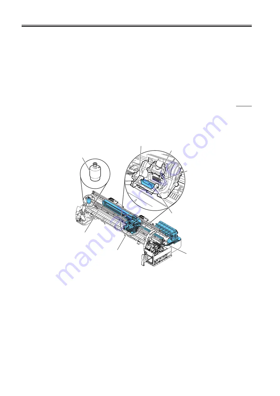
2.3.2.3.2 Structure of carriage
0009-1512
a) Printhead mounting unit
The printhead are mounted to the carriage by the printhead lock cover and printhead lock lever. When the printhead are fixed to the carriage, the signal
contact point of the head relay PCB contacts the signal contact point of the printhead, and this results in the transmission of print signals. Also, the ink
passage from the ink tank passes through the ink tube and connects to the printhead.
b) Ink port
Ink passes through the ink tube and is supplied to the printhead.
The ink tubes run through the joints and the tube guide and as they move in coordination with the carriage.
F-2-11
c) Control unit
The carriage relay PCBs are connected to the head relay PCBs by short flexible cables. The flexible cable between the engine controller and carriage relay
PCB moves in coordination with the carriage together with the tube guide.
A photocoupler-type encoder is mounted at the bottom of the rear of the carriage for reading the linear scale during carriage movement.
d) Carriage drive unit
Mechanical misalignment of the installed printhead in the vertical/horizontal direction and in bidirectional printing can be corrected by using the "Adjust
Printer" command in the Main Menu to shift the print timing.
The carriage belt, which is driven by the power from the DC motor-type carriage motor, moves the carriage in the sheet horizontal direction.
The carriage home position which is the capping position is detected by the sensor plug (printhead height adjustment lever) on the right side of the carriage
and the photo interrupter-type carriage home position/head height sensor on the main body right-side plate. The position on the linear scale that corresponds
to the detected carriage homeposition is recorded as the homeposition, and this position is set as the reference point for position control. The carriage motor
is then driven and controlled using the control signals generated by the engine controller.
Contact
Ink supply joint
Ink tube
Printhead lock lever
Tube guide
Carriage
Carriage motor
Printhead lock cover
Summary of Contents for W8400 Series
Page 1: ...Apr 5 2005 Service Manual W8400 Series W8400 ...
Page 2: ......
Page 6: ......
Page 12: ...Contents ...
Page 13: ...Chapter 1 PRODUCT DESCRIPTION ...
Page 14: ......
Page 16: ......
Page 21: ...Chapter 1 1 5 F 1 9 ...
Page 47: ...Chapter 2 TECHNICAL REFERENCE ...
Page 48: ......
Page 91: ...Chapter 3 INSTALLATION ...
Page 92: ......
Page 94: ......
Page 97: ...Chapter 4 DISASSEMBLY REASSEMBLY ...
Page 98: ......
Page 100: ......
Page 138: ......
Page 139: ...Chapter 5 MAINTENANCE ...
Page 140: ......
Page 142: ......
Page 146: ......
Page 147: ...Chapter 6 TROUBLESHOOTING ...
Page 148: ......
Page 193: ...Chapter 6 6 43 F 6 8 Cover switch tool Cover switch tool ...
Page 194: ......
Page 195: ...Chapter 7 SERVICE MODE ...
Page 196: ......
Page 198: ......
Page 212: ......
Page 213: ...Chapter 8 ERROR CODE ...
Page 214: ......
Page 216: ......
Page 222: ......
Page 223: ...Apr 5 2005 ...
Page 224: ......