background image

Chapter 1  

1-2

1.2 Features

1.2.1 Features

0008-6297

- Light and compact body made possible by rear feeding of roll media.

- Four-sides borderless printing support (roll media) eliminates tedious cutting and simplifies poster creation.

- High quality photo finish with 2400 x 1200 dpi maximum resolution using highly lightfast, water-proof, and ozone-proof six color (C, M, Y, Bk, MBk,

PC, PM) pigment ink. (Choose either Bk or MBk)

- High-speed printing with bidirectional print control using 1 inch (1280-nozzles) head

for each color.

- Tubing type ink supply completely separating print head and large capacity ink tank.

- Support for roll media and cut sheets.

- Roll media with width from 203.2 to 609.6 mm and length up to 18 m can be used.

- Carriage mounted cutter mechanism enables automatic sheet cutting.

- Cut sheet feeding, media discharge, and ink tank replacement can be performed easily from the front.

- Standard support for high-speed USB2.0 interface. Optional support for 10Base-T/100Base-TX TCP/IP network or IEEE1394.

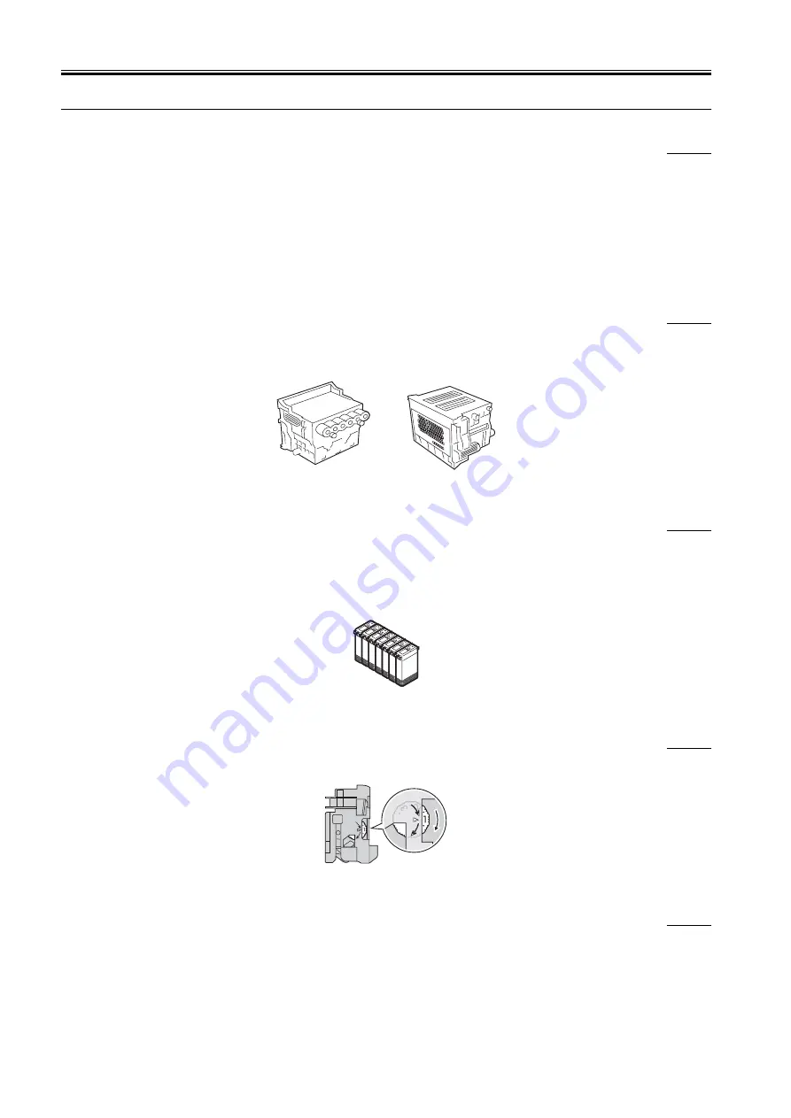
1.2.2 Printhead

0008-6298

On the carriage, disposable printhead is installed, each of which contains six rows of integrated nozzles.

Each row consists of 1280 nozzles, which are arranged in a staggered pattern for printing efficiency.

If print quality does not improve despite carrying out cleaning, the printhead should be replaced with a new one. Generally, it is recommended that the

print head be replaced about 12 months after you have opened the package. 

F-1-2

1.2.3 Ink Tank

0008-6299

The ink tank is disposable.

There are six colors: Black, Photo Cyan (PC), Cyan (C), Photo Magenta (PM), Magenta (M) and Yellow (Y), each using pigment based ink. Either Black

(Bk) or Matte Black (MBk) can be selected for Black.

To install an ink tank, open the right cover of the printer and insert the tank. The printer features a mechanism by which only the correct color ink tank will

fit in its given slot.

When the "No Ink" message is displayed, replace the ink tank with a new one. Also, the ink tanks should generally be replaced 6 months after you have

opened the package.

F-1-3

1.2.4 Cutter Unit

0008-6300

A disposable cutter unit is mounted on the carriage.

When the cutter becomes dull, increment the position adjustment dial by 1. If the dial is at 3, replace with a new cutter unit.

F-1-4

1.2.5 Roll Holder

0008-6301

A roll holder for a 2-inch inner diameter paper tube is included as standard accessory. Roller holders for 2-inch inner diameter paper tube and 3-inch inner

diameter paper tube are set as option. 

Both roll holders lock into the cardboard tube of roll media with an outer diameter not more than 6 inch (150 mm).

Summary of Contents for W6400 Series

Page 1: ...Apr 5 2005 Service Manual W6400 Series W6400 ...

Page 2: ......

Page 3: ... need arises In the event of major changes in the contents of this manual over a long or short period Canon will issue a new edition of this manual The following paragraph does not apply to any countries where such provisions are inconsistent with local law Trademarks The product names and company names used in this manual are the registered trademarks of the individual companies Copyright This ma...

Page 4: ...quiring care to avoid combustion fire Indicates an item prohibiting disassembly to avoid electric shocks or problems Indicates an item requiring disconnection of the power plug from the electric outlet Indicates an item intended to provide notes assisting the understanding of the topic in question Indicates an item of reference assisting the understanding of the topic in question Provides a descri...

Page 5: ...sed to indicate Low The voltage value however differs from circuit to circuit In addition the asterisk as in DRMD indicates that the DRMD signal goes on when 0 In practically all cases the internal mechanisms of a microprocessor cannot be checked in the field Therefore the operations of the microprocessors used in the machines are not discussed they are explained in terms of from sensors to the in...

Page 6: ......

Page 7: ...nter Status 1 11 1 6 3 Main Menu 1 11 1 7 Safety and Precautions 1 18 1 7 1 Safety Precautions 1 18 1 7 1 1 Moving Parts 1 18 1 7 1 2 Ink 1 18 1 7 1 3 Electrical Parts 1 20 1 7 2 Other Precautions 1 21 1 7 2 1 Printhead 1 21 1 7 2 2 Ink Tank 1 21 1 7 2 3 Handling the Printer 1 22 1 7 3 Precautions When Servicing Printer 1 23 1 7 3 1 Stored Data 1 23 1 7 3 2 Firmware Confirmation 1 23 1 7 3 3 Preca...

Page 8: ... 2 27 2 4 3 1 Engine controller components 2 27 2 4 4 Carriage Relay PCB 2 28 2 4 4 1 Carriage relay PCB components 2 28 2 4 5 Head Relay PCB 2 28 2 4 5 1 Head relay PCB components 2 28 2 4 6 Power Supply 2 29 2 4 6 1 Power supply block diagram 2 29 2 5 Detection Functions Based on Sensors 2 30 2 5 1 Sensors for covers 2 30 2 5 2 Ink passage system 2 31 2 5 3 Carriage system 2 33 2 5 4 Paper path ...

Page 9: ...ng 6 1 6 1 1 Outline 6 1 6 1 1 1 Outline of Troubleshooting 6 1 6 1 2 Troubleshooting by the Phenomenon 6 1 6 1 2 1 Incorrect Value Check Value 6 1 6 1 2 2 Offline Load Roll Media 6 1 6 1 2 3 Offline Load Cut Sheet Offline Remove Cut Sheet 6 1 6 1 2 4 Offline Open Upper Cover 6 2 6 1 2 5 Printer Setup Open Upper Cover 6 2 6 1 2 6 Printer Setup Open Right Cover 6 2 6 1 2 7 Printer does not turn on ...

Page 10: ...or 6 10 6 1 4 20 E02B06 Carriage cover sensor error 6 10 6 1 4 21 E02B08 Paper release lever error 6 10 6 1 4 22 E02D00 E02D01 E02D0A E02D0B Sensor error in purge unit 6 11 6 1 4 23 E02D02 Carriage homeposition error 6 11 6 1 4 24 E02D03 Feed motor error 6 11 6 1 4 25 E02D05 Air flow fan error 6 11 6 1 4 26 E02D06 Ink supply valve switching error 6 12 6 1 4 27 E02D07 Feed roller home position sens...

Page 11: ...Contents Chapter 8 ERROR CODE 8 1 Outline 8 1 8 1 1 Outline 8 1 8 2 Warning Table 8 2 8 2 1 Warnings 8 2 8 3 Error Table 8 3 8 3 1 Errors 8 3 8 4 Sevice Call Table 8 5 8 4 1 Service call error list 8 5 ...

Page 12: ...Contents ...

Page 13: ...Chapter 1 PRODUCT DESCRIPTION ...

Page 14: ......

Page 15: ...it 1 9 1 5 4 Internal part 1 9 1 6 Basic Operation 1 10 1 6 1 Operation Panel 1 10 1 6 2 Change of Printer Status 1 11 1 6 3 Main Menu 1 11 1 7 Safety and Precautions 1 18 1 7 1 Safety Precautions 1 18 1 7 1 1 Moving Parts 1 18 1 7 1 2 Ink 1 18 1 7 1 3 Electrical Parts 1 20 1 7 2 Other Precautions 1 21 1 7 2 1 Printhead 1 21 1 7 2 2 Ink Tank 1 21 1 7 2 3 Handling the Printer 1 22 1 7 3 Precautions...

Page 16: ......

Page 17: ...hes wide The printer is a desktop type The printer is capable of output to either roll media or cut sheet F 1 1 Right upper cover Power connector IEEE1394 or 10Base T 100Base TX port option USB port Operation panel Right cover Stand assembling tool Hex key wrench Belt stopper Cleaning brush Ink tank Printhead Roll holder Holder stopper Output stacker Stand option Left front cover Upper cover ...

Page 18: ...ed pattern for printing efficiency If print quality does not improve despite carrying out cleaning the printhead should be replaced with a new one Generally it is recommended that the print head be replaced about 12 months after you have opened the package F 1 2 1 2 3 Ink Tank 0008 6299 The ink tank is disposable There are six colors Black Photo Cyan PC Cyan C Photo Magenta PM Magenta M and Yellow...

Page 19: ...umable ink tank are available in six colors Black Bk Matte Black MBk Photo Cyan PC Cyan C Photo Magenta PM Magenta M and Yellow Y They are all identical with the ink tank shipped with the printer Each bottle has a life of 6 months from the time the package is opened F 1 7 Cutter unit The consumable cutter unit is the same as the cutter unit shipped with the printer F 1 8 ...

Page 20: ...400mm 5 12 Printable area Roll media Bordered printing Area excluding 5 mm from the top 5 mm from the bottom and 5 mm from the left and right edges Borderless printing 0 mm from the top bottom left and right edges 1 Borderless printing supports JIS B2 10 inch 14 inch 16 inch and 24 inch 2 Printable area may depend on the media Printable area Cut sheet Area excluding 5 mm from the top 23 mm from th...

Page 21: ...tection Yes Paper release lever position detection Yes Roll media trailing edge detection Yes Remaining roll media detection Yes Feed roller rotation detection Yes Operating noise Sound pressure level 1 During standby Approx 35dB A max During printing Approx 50dB A max High mode 1 Based on ISO9296 sound pressure level Operating environment Operating environment Temperature 5 deg C to 35 deg C Humi...

Page 22: ...Draft 4 pass 1200x1200dpi Approx 2 0 min Standard 6 pass 1200x1200dpi Approx 3 0 min High 8 pass 2400x1200dpi Approx 6 7 min Photo Glossy Paper Photo Semi Glossy Paper Photo Glossy Paper HW Photo Semi Glossy Paper HW Special1 5 Standard 8 pass 1200x1200dpi Approx 3 9 min High 8 pass 2400x1200dpi Approx 6 7 min Highest 16 pass 2400x1200dpi Approx 13 1 min Fine Art Photo Fine Art Photo HW Fine Art T...

Page 23: ...Output Differential output voltage 172 mV to 265 mV 4 Interface cable Twisted pair shielded cable 4 5 m max Compliance with IEEE1394 1995 standards or P1394a Version 2 0 standards 5 Interface connector Printer side IEEE1394 standards 6 pin connector socket Cable side IEEE1394 standards 6 pin connector plug c Network option 1 Interface format Interface complying with IEEE802 3 standards 2 Data tran...

Page 24: ...per jams inside the printer and other operations Operation panel The operation panel includes the Power button Online button and display Right cover Thi s cover is locked when the printer is printing or sucking ink It is unlocked during standby or when replacing the ink tank Paper delivery assist guide Pull out when printing It pr event s the paper fr om hitting against the head Push in when cutti...

Page 25: ...o lock the printhead This is opened when installing the printhead Printhead Carriage cover This cover protects the carriage This cover is opened when installing the printhead Carriage Print head lock lever This lever is used to lock the printhead lock cover This lever is opened when installing the printhead Maintenance cartridge ...

Page 26: ...r ink drying and then discharges the media Pause status Holding down this button for 1 seconds or longer aborts the paused job and discharges the media 7 button Offline status Holding down this button for 1 second or longer moves the carriage to the center of platen When a menu is displayed This button functions as a selector button and is used to display the next option This button functions as a...

Page 27: ...tures auto cutting ink drying time and other print settings message language and other parameter settings 1 Main menu operations a How to enter the Main Menu To enter the Main menu press the printer s Online button several times b How to exit the Main Menu Press the Online button once to exit the Main menu c Buttons used in the Main Menu Selecting menus and parameters button or button Entering a l...

Page 28: ...p menu Med Detail Set Plain Paper YES NO Printing adjustment menu Adjust Printer Interface setup menu Interface Setup YES NO YES NO System setup menu System Setup Information menu Information Head Cleaning MAIN MENU Head Cleaning B Head Cleaning A Force Cutting Media Type 1 Change Bk Ink Type 2 Rep Ink Tank 3 Maintenance Replace P head 2 Move Printer 2 Test Print Status Print Media Details Print J...

Page 29: ... Med Detail Set Plain Paper Drying_Time Return Defaults Width Detection Skew Check Lv Correct Smear CutDustReduct Cut Speed Standard Cutter VacuumStrngth Media Thickness Far End RllMrgn NearEnd RllMrgn Scan Wait Time Off 30 seconds 1 min 3 5 10 30 min 60 min Off 1 sec 3 5 7 sec 9 sec Thick Standard Thin Weak Standard Strong Very Strong Enable Disable Standard Fast Standard Off Loose ...

Page 30: ...fault values are underlined 1 Displayed when Band Joint is selected for Feed Priority Adjust Printer Printhead Adj Color Calib Adjust Length 1 Adjust Band Feed Priority Advanced Adj Auto Print Standard Adj Fine Tuning No Yes Standard Adj Advanced Adj Return Defaults Color Calib PM Color Calib K Band Joint Print Length ...

Page 31: ...e IP Mode On Off BOOTP On Off RARP On Off 0 255 0 255 0 255 0 255 Bindary Pserver RPrinter Off On Ethernet2 Ethernet802 2 Ethernet802 3 EthernetSNAP NDSPserver Nprinter Interface Setup EOP Timer NetWare 1 TCP IP 1 TCP IP On IP Setting 3 Protocol 2 IP Mode NetWare Print Service Frame Type 10 sec 30 sec 1 2 5 10 30 min 60 min Manual Automatic IP Address 0 255 0 255 0 255 0 255 0 255 0 255 0 255 0 25...

Page 32: ...Remain Roll is On 2 Displayed when Length Unit is Meter 3 Displayed when Length Unit is Feet On Off English Espanol No Yes System Setup Warning Change Cutter Keep Media Size Roll Length Set 1 Off On Chk Remain Roll Reset MediaType Language Length Unit Use Power Save Sleep Timer Stop Ink Check Nozzle Check Buzzer Med type Wrning Head Ht Wrning Off 1 Page 10 Pages Bk Ink Tank Y Ink Tank PC C PM M In...

Page 33: ...XXXXXX 1 XXXXX 2 XXXXX Version Information Counter Job Log Error Log MAC Address 1 Ext Interface RAM Document Name Coverage User Name Page Count Job Status Print Start Time Print End Time Print Time Print Size Media Type Interface Job Log 1 Job Log 3 Job Log 2 Cut Count 1 Displayed only when Network board is installed ...

Page 34: ...touch the ink passages of the printer or to allow ink to stain theworkbench hands clothes or the printer under repair The ink flows through the ink tank unit carriage unit purge unit maintenance jettray maintenance cartridge and the ink tubes that relay ink to each unit Although the ink is not harmful to the human body it contains organicsolvents Avoid getting the ink in your mouth or eyes Flush w...

Page 35: ...ince the printhead prints by squirting ink onto the media a minute amount of inkmist is generated in the printing unit during printing The ink mist is collected in the printer by the airflow However uncollected ink mist may stain the platen unit carriage unit main rail unit external unit or purge unit These stains may soil the print media or hands and clothes when servicing the printer wipe them o...

Page 36: ...ead relay PCB and carriage relay PCB are incorporated in the carriage unit and the operation panel is located on the upper right cover When servicing the printer with the cover removed be extremely careful to avoid electric shock and shorting contacts F 1 26 Purge unit Upper cover Platen unit Carriage unit Main rail unit System controller Engine controller Power supply Power connector Head relay P...

Page 37: ...e then power off the printer using the power button Improper capping may cause clogged printhead nozzles due to dried ink or ink leakage from the printhead 3 When the printer is not used for a long time Keep the printhead installed in the printer even when it is not used for an extended period of time If the printhead is left uninstalled printing failure may arise from clogged nozzles due to the d...

Page 38: ...the carriage at the carriage home position so that the carriage does not become separated from the lock arm This will prevent damage and ink leakage during transportation F 1 30 3 Replacing the maintenance cartridge When the maintenance cartridge detects that tank is full the Replace MT cartridge error appears In this case the maintenance cartridge must be replaced The printer will not operate unt...

Page 39: ...urge unit The information on the number of cleanings is generated from the purge unit Initialize clear the number of cleanings information after replacing the purge unit You cannot check the counter information once it is initialized cleared Be careful that you do not perform the initialization before checking the information Also you cannot modify the counter information from the operation panel ...

Page 40: ......

Page 41: ...Chapter 2 TECHNICAL REFERENCE ...

Page 42: ......

Page 43: ...2 3 2 3 2 Structure of carriage 2 12 2 3 2 4 Printhead 2 13 2 3 2 4 1 Structure of printhead 2 13 2 3 2 5 Purge Unit 2 14 2 3 2 5 1 Functions of purge unit 2 14 2 3 2 5 2 Structure of purge unit 2 16 2 3 2 6 Maintenance Cartridge 2 18 2 3 2 6 1 Maintenance cartridge 2 18 2 3 2 7 Air Flow 2 19 2 3 2 7 1 Air flow 2 19 2 3 3 Paper Path 2 19 2 3 3 1 Outline 2 19 2 3 3 1 1 Overview of paper path 2 19 2...

Page 44: ...ents 2 4 6 1 Power supply block diagram 2 29 2 5 Detection Functions Based on Sensors 2 30 2 5 1 Sensors for covers 2 30 2 5 2 Ink passage system 2 31 2 5 3 Carriage system 2 33 2 5 4 Paper path system 2 34 ...

Page 45: ...PCB Ink tank unit Valve motor Valve cam sensor Valve motor unit Purge unit Pump motor Purge motor Pump homeposition sensor Cap sensor Upper cover lock solenoid R Carriage motor Operation panel Head relay PCB Printhead Carriage relay PCB Carriage unit Registration sensor Linear encoder Carriage cover sensor System controller Expansion board Expansion Optional Power supply To power cord Power button...

Page 46: ...RAM at the optimal timing and the data is combined with the mask data in the ASIC and output in coordination with the discharge timing The ASIC also sends the command data from the system controller to the CPU f The CPU in the engine controller obtains the mask pattern data from the FLASH ROM based on the command data printhead information from the EEPROM in the printhead and internal temperature ...

Page 47: ...head nozzles in the selected block heat enable signals and subheat enables signals are applied to adjust the pulse width according to the head rank head temperature internal temperature and other factors to ensure optimal ink discharge and then the heat board in the printhead nozzle is driven so that ink is discharged The optimal nozzle block is selected based on the printing pass F 2 3 2 Print dr...

Page 48: ...0dpi E_DATABK1 E_DATABK2 Low active Low active Linear scale Data of block 0 Data of block 0 Data of block 0 Data of block 0 Data of block 2 Data of block 2 Data of block 2 Data of block 2 Data of block 4 Data of block 4 Data of block 4 Data of block 4 Data of block 22 Data of block 22 Data of block 22 Data of block 22 ...

Page 49: ...ters the online state and then press the power button to turn off the power 1 Power Off sequence Device resource initialization initialization Engine status check Cleaning No media Media detected Media detection Media load Upper cover Right cover lock release Maintenance cartridge check Printhead Ink tank check Upper cover Right cover lock Valve motor check Power button ON Waiting for media loadin...

Page 50: ...n under Print Quality settings in the printer driver The printer operation in standard mode depends on the printer driver sheet setting When printing in 6 pass bi directional format the image data is divided into three parts for each color under mask pattern control and then nozzle block control is used to further divide this data into two parts for printing When printing in 8 pass bi directional ...

Page 51: ...r Color Coated Paper Newspaper Proofing Paper 1 Newspaper Proofing Paper 2 Newspaper Proofing Paper 3 1200x1200 600 6 Bi directional Plain paper CAD Tracing paper CAD Translucent Matte Film CAD 1200x1200 300 8 Bi directional Photo Glossy Paper Photo Semi Glossy Paper Photo Glossy Paper HW Photo Semi Glossy Paper HW Japanese Paper Proofing Paper 2 Synthetic Paper Adhesive Synthetic Paper Flame Resi...

Page 52: ...carriage to continue in the direction of its scanning pass and then stops it at the scan end position The wait control is activated to allow the heat to dissipate Printing resumes when the temperature drops below 80 deg C 2 1 When using MBk ink when the Bk nozzle head temperature sensor detects temperature of 70 deg C or higher 2 When using MBk ink when the Bk nozzle head temperature sensor detect...

Page 53: ...ng transport and discharge of media This section presents an overview of the components of the mechanical system F 2 7 2 3 2 Ink Passage 2 3 2 1 Ink Passage 2 3 2 1 1 Overview of the ink passage 0008 6340 The ink passage consists of the ink tanks printhead caps maintenance jet tray maintenance cartridge ink tubes for connecting the mechanical components and ink suction pump that is activated when ...

Page 54: ...le Therefore do not open all of the ink passages at the same time when the ink tube is filled with ink 2 3 2 2 Ink Tank Unit 2 3 2 2 1 Structure of ink tank unit 0008 6341 a Ink tank The ink tanks contain ink approx 130 ml for each color The amount of ink is stored in the EEPROM mounted on the ink tank The remaining ink level in the ink tank is detected using a dot count based on the EEPROM inform...

Page 55: ... moves the carriage back and forth on the platen The carriage belt is driven by the power from the carriage motor d Printhead maintenance This printer has a cleaning function that performs wiping and suction of the printhead when the carriage is stopped at the carriage homeposition e Nozzle check This printer detects non discharging printhead with the head management sensor attached to the mainten...

Page 56: ... and the tube guide and as they move in coordination with the carriage F 2 11 c Control unit The carriage relay PCBs are connected to the head relay PCBs by short flexible cables The flexible cable between the engine controller and carriage relay PCB moves in coordination with the carriage together with the tube guide A photocoupler type encoder is mounted at the bottom of the rear of the carriage...

Page 57: ...the face of the printhead and the media g Registration sensor unit The resistration sensor at left bottom of the carriage consists of two LEDs and receiver sensor h Rail cleaner unit The rail cleaner at far right of the carriage is used to prevent contamination of the rail i Internal temperature detection A thermistor for measuring the internal temperature is installed on the head relay PCB on the...

Page 58: ...suction operation and when switching to the standby state due to an error The capping operation also connects the ink passage between the printhead and purge unit b Cleaning Cleaning includes a wiping operation for removing paper fibers and dried ink deposits adhering to the nozzle face plates of the printhead a suction operation for removing ink from the nozzles and drawing new ink to refresh the...

Page 59: ...atus Cleaning Description Consumption reference 1 At power on Initial installation Cleaning 3 initial filling cleaning Approx 35g When the power is turned ON at least 1440 hours but less than 2160 hours have elapsed since the previous ink level adjustment suction or initial filling suction 2 Cleaning 2 ink level adjustment cleaning Approx 11g When the power is turned ON at least 2160 hours have el...

Page 60: ...s operated by the purge motor to cover the arrays when the carriage has moved to the homeposition Capping is also performed during the cleaning operation and the suction pump is then used to remove ink from the printhead When Head Cleaning menu is selected Manual cleaning Head Cleaning A Cleaning 1 normal cleaning Approx 1g Manual cleaning Head Cleaning B Cleaning 6 normal strong cleaning Approx 6...

Page 61: ...wiping the wiper blades are cleaned before they are set at the wiping position so that maximum wiping performance can be maintained In the wiper blade cleaning ink that was wiped from the head section is rubbed off by an ink scrapping receptacle connected to the maintenance cartridge and then the blades are wiped off with a blade cleaner F 2 17 c Pumps In this printer tube pumps press on the ink t...

Page 62: ...cartridge an error message Replace MT Cart appears to indicate that the maintenance cartridge is full When the printer judges the maintenance cartridge as being full of waste ink it stops printing immediately The printer will not operate unless the maintenance cartridge is replaced with a new one MEMO This printer has an EEPROM in the maintenance cartridge and the maintenance cartridge status is c...

Page 63: ...feed rollers pinch roller drive unit for pressing and releasing the pinch rollers and sensors for detecting the media feeding status The paper path performs manual feeding transport and delivery for the roll media and cut sheets The diagram below presents an overview of the paper path and its operations F 2 21 Roll media feeding is performed mainly when the power is turned on or when the media is ...

Page 64: ...edia set position 2 Drive the carriage and move the registration sensor over the media 3 Determine sensor output and check the registration sensor input value over the media 4 Drive the carriage and move the registration sensor over the platen 5 Check the sensor input value over the platen 6 Determine the sheet edge threshold 7 Retract the head from the media to prevent head wear 8 Feed the media ...

Page 65: ...Drive the carriage and feed roller and move to barcode reference pattern detection position 2 Drive the carriage and detect the barcode reference pattern 3 Drive the carriage and feed roller and move to barcode data pattern detection position 4 Drive the carriage and detect the barcode data pattern 5 Repeat steps 3 and 4 five times because the pattern has 6 lines 6 Move the carriage to home positi...

Page 66: ...he media left edge temporarily stop forward movement of the carriage when detected Compare with the media left edge determined during media width detection to determine the skewing amount Media leading edge detection shutdown 1 Move the registration sensor over the platen at left edge of the media Media trailing edge detection 1 Feed the media forward and tentatively detect the media trailing edge...

Page 67: ... For more information see Technical Reference Detection Functions Based Sensors Media trailing edge detection 1 Feed the media forward and tentatively detect the media trailing edge with the media sensor temporarily stop feeding when detected 2 Feed the media backward and detect the media trailing edge with the media sensor stop feeding when detected Registration sensor calibration 1 Move the regi...

Page 68: ...utter When Autocut Yes is selected in the Printer Driver the cutter unit mounted on the left side of the carriage automatically cuts the roll media However the roll media is not cut if it is suppressed by the Printer driver F 2 27 Cut sheet Pinch roller Feed roller Paper release lever Cutter unit ...

Page 69: ...Power supply 3 3 V generation function 5 1 V generation function 26 5 V generation function Printhead Carriage unit Head relay PCB Temperature reading control function Sensors DI sensor reading control function Sensors Feed motor AC inlet Optional connector assembly Fan control function Solenoid control function Motor control function Sensor detection function Image data control function Mask conv...

Page 70: ...CPU has the following functions 1 DMA controller The DMA controller manages the USB expansion card slots and other input interfaces and DMA transfer of the data stored in the DDR SDRAM 2 Interrupt controller The interrupt controller receives and processes external interrupts from USB image processing unit and expansion card slots in addition to the internal interrupts 3 Power supply on off control...

Page 71: ...generates the image data for printing each color from the image data received from the system controller and mask pattern corresponding to the print mode in the SDRAM IC501 IC502 and stores it in SDRAM IC506 IC507 This function also controls the output of the generated image data to the carriage relay PCB Heat enable signal control This functions uses the pulse width to perform variable control of...

Page 72: ...er IC703 This motor driver is used to perform constant current driving of the purge motor which is a stepping motor m Motor driver IC727 This motor driver is used to perform constant current driving of the valve motor which is a stepping motor n Regulator IC729 The regulator IC generates the engine internal driving power supply 3 3 V o Regulator IC728 The regulator IC generates the CPU IC511 and A...

Page 73: ...niversal power supply converts AC voltages ranging from 100 V to 240 V supplied from the AC inlet to DC voltages for supplying the driving voltages of ICs motors and other parts The voltage generating circuits are divided into the power supply system for driving the motors 26 5 V and sensors 5 1 V and the power supply system for driving the logic circuits 3 3 V The 26 5 V 5 1 V system uses a combi...

Page 74: ...itting of the upper cover sensors are located on both the right and left sides Right cover sensor The photo interrupter based right cover sensor detects the opening and closing of the right cover When the right cover is closed the sensor light is cut off by the sensor arm and this notifies the sensor that the right cover is closed MEMO When the upper cover is closed the 26 5 V power is supplied by...

Page 75: ...he pulse motor based on the timing when the sensor light is cut off F 2 36 Pump homeposition sensor The photo interrupter based pump sensor detects the homeposition of the suction pump rollers The homeposition of the pump is defined as the position where the rotary flag which operates in conjunction with the drive gear shaft of the rollers cuts off the sensor light Cap sensor Pump homepositio sens...

Page 76: ...ed for their normal ink discharging operations This process is repeated for the rest of the 5 nozzle arrays of the printhead If the sensor light is blocked by the ink discharged from a nozzle and the voltage measured by the sensor changes that nozzle is proved to work correctly F 2 39 Sensor Homeposition During suction Homeposition Rotary flag Sensor Rotary flag Close Close Close Close Close Close...

Page 77: ...rriage home position is defined based on the location where the sensor flag is detected Linear encoder The linear encoder installed on the rear of the carriage detects the position of the carriage using the slits on the linear scale while the carriage is moving Environment temperature sensor The environment temperature sensor thermistor installed on the head relay PCB detects the environment tempe...

Page 78: ...pply terminal and the GND terminal 2 5 4 Paper path system 0008 6361 F 2 42 Media sensor The photo reflection based media sensor detects if paper is on the platen The sensor detects the presence of paper by receiving the sensor light reflected from the paper Feed roller home position sensor The feed roller home position sensor detects the change from white transparent to black opaque of the refere...

Page 79: ...Chapter 3 INSTALLATION ...

Page 80: ......

Page 81: ...Contents Contents 3 1 Transporting the Printer 3 1 3 1 1 Transporting the Printer 3 1 3 1 1 1 Transporting The Printer 3 1 3 1 2 Reinstalling the Printer 3 2 3 1 2 1 Reinstalling the Printer 3 2 ...

Page 82: ......

Page 83: ...stand 7 Hold the printer carrying handle at the bottom and then slowly move the printer If the printer is subjected to strong vibrations when it is moved it can cause ink leakage or damage to the printhead Be sure to move the printer slowly and carefully 2 How to transport the printer to a different floor Follow the steps shown in a When the printer is operating properly When the printer is not op...

Page 84: ...operation 6 Remove the maintenance cartridge and then package it so that the waste ink does not leak from it 7 Attach all of the exterior covers 8 Open the upper cover and then use the belt stopper to secure the carriage in place Refer to PRODUCT DESCRIPTION Safety and Precautions Other Precautions Handling the Printer Fixing the carriage 9 Close the upper cover 10 Attach the cushioning materials ...

Page 85: ...g for the first time 1 Unpack the printer and mount the printer on a stand if a stand is included 2 Remove the cushioning materials and tape 3 Reattach the maintenance cartridge 4 Remove the belt stopper 5 Connect the power cord 6 Turn on the power and following the instruction in the message to install the ink tank The ink is filled 7 Load the media and perform the operation check ...

Page 86: ......

Page 87: ...Chapter 4 DISASSEMBLY REASSEMBLY ...

Page 88: ......

Page 89: ... 7 Carriage unit 4 12 4 3 8 Feeder unit 4 15 4 3 9 Purge unit 4 15 4 3 10 Head management sensor 4 16 4 3 11 Ink tank unit 4 16 4 3 12 Boards 4 17 4 3 13 Opening the Caps and Moving the Wiper Unit 4 18 4 3 14 Opening and Closing the Ink Supply Valve 4 19 4 3 15 Draining the Ink 4 19 4 4 Applying the Grease 4 22 4 4 1 Applying The Grease 4 22 4 5 Adjustment and Setup Items 4 24 4 5 1 Adjustment of ...

Page 90: ......

Page 91: ...s boxes marked This side up and handle appropriately F 4 1 2 Feed roller The feed roller is a functionally important part Therefore be careful that the roller is not scratched or marked during storage or transport of the service parts when removing them from the individual boxes when assembling or performing any other operations For details about handling of the feed roller refer to DISASSEMBLY RE...

Page 92: ...3 Roll holder slot right s4 Paper release lever Right bottom cover s2 Right cover s1 h3 Front cover s2 h2 EEPROM cable c4 Paper delivery guide s2 Valve motor unit c2 s3 Valve motor unit cover c1 s2 Carriage home position sensor h2 Tube base cover h4 Cable mount s1 Carriage relay PCB s2 Tube base s2 Feed roller s2 Cover stay left s2 c2 Cover stay right s2 c3 Left front cover s1 Feed roller sensor c...

Page 93: ...peration panel for at least 0 5 seconds when the printer is offline However when the power is turned off such as during assembly or disassembly move the carriage by holding the knobs shown in the figure below Move the carriage as required during assembly and disassembly to prevent contact of the carriage with the parts that are removed The carriage does not move when capping has been performed Ref...

Page 94: ...SASSEMBLY REASSEMBLY Points to Note on Disassembly and Reassembly Carriade unit Ink tube unit Refer to page DISASSEMBLY REASSEMBLY Points to Note on Disassembly and Reassembly Ink tube unit Ink tank unit Refer to page DISASSEMBLY REASSEMBLY Points to Note on Disassembly and Reassembly Ink tank unit F 4 5 4 3 4 Outer covers 0009 8785 a Upper cover When removing the upper cover fully open the upper ...

Page 95: ...om the left unhook two hooks securing the operation panel and push it toward your side and pull out the inserts at three locations on the upper side Remove the two connectors connecting the cable connected to the rear of the operation panel F 4 9 d Right upper cover When removing the right upper cover first open the upper cover then remove the operation panel lids of right side cover right side co...

Page 96: ...right side Next remove the entire right cover by pulling in an upward motion while pressing on the bottom and left side surfaces F 4 11 f Front cover Remove the front cover by disengaging the two hooks on the bottom of the cover and then slide the cover to the right and pull forward hooks at three locations at the top Because the cover must be moved to the right it will be necessary to first remov...

Page 97: ...er and the paper release lever The hook located at the top end of the upper rear cover is engaged in the cover stay so first rotate the top of the upper rear cover by 90 degrees in order to remove the hook F 4 13 h Rear cover When removing the rear cover remove 12 screws and remove the bottom end first Front cover 1 2 1 Hook Hook Hook Cover stay Upper rear cover ...

Page 98: ...e gear unit F 4 15 4 3 5 Driving unit 0009 8786 a Drive belt for driving the feed roller To mount the drive belt for driving the feed roller loosen the setscrews of the tensioner and then use the spring pressure to determine the tension of the drive belt Once the belt is mounted use the setscrews to secure the tensioner in place F 4 16 Rear cover Mark Paper release lever Pinch roller cam Timing be...

Page 99: ...a size 24 inch 4 3 6 Ink tube unit 0009 8787 a Removing the ink tube unit 1 Drain the ink For details refer to DISASSEMBLY REASSEMBLY Points to Note on Disassembly and Reassembly Draining the Ink 2 Turn off the power and then move the carriage over the platen For details refer to DISASSEMBLY REASSEMBLY Points to Note on Disassembly and Reassembly Opening the Caps and Moving the Wiper Unit 3 Remove...

Page 100: ...k remaining in the tube to flow to the maintenance cartridge 10 Remove the printhead 11 Remove the printhead lock lever 12 Wrap the joint on the ink tube unit with a plastic bag or other covering so that no ink splashes or leaks and then close the plastic bag F 4 20 13 Release the cable cover claw and remove it from the frame 14 Remove the screw and detach the cable mount from the frame Joint Ink ...

Page 101: ...iage F 4 22 b Assembling the ink tube unit If replacing the ink tube unit turn on the power when the printhead and ink tank are not installed and then install the printhead and ink tank by following the messages and refill the ink Cable mount Setscrew Cable cover Setscrew Ink tube unit ...

Page 102: ...ving the Wiper Unit 3 Remove the shaft cleaner holder cover and tube holder 4 Remove the printhead 5 Remove all the connectors on the carriage relay PCB 6 Remove the printhead lock lever 7 Wrap the printhead side joint on the ink tube unit with a plastic bag or other covering so that no ink splashes or leaks then close the plastic bag F 4 23 8 Remove the screw and take off the ink tube unit from t...

Page 103: ...iage unit and nozzle in the print head Therefore adjustment must be performed when replacing or disassembling assembling the carriage unit or registration sensor Enter the service mode under the following condition Service mode SERVICE MODE ADJUST PRINT PATTERN OPTICAL AXIS Head height LOW position Media type Photo Glossy Paper Media size 24 inch d Removing the head holder 1 Drain the ink For deta...

Page 104: ...ring so that no ink splashes or leaks and then close the plastic bag F 4 27 9 Use a flat head screwdriver or other tool to press the lock pin at the left rear side of the head holder in the direction of the arrow and open the head holder F 4 28 10 Open the grips of the head holder and remove the head holder F 4 29 e Assembling the head holder After assembling the head holder check that the head ho...

Page 105: ...ecision Therefore adjustment must be made when the feed roller feed roller HP sensor or feed roller encoder which affect the decentration compensation is replaced or disassembled assembled Enter the service mode under the following condition Service mode SERVICE MODE ADJUST PRINT PATTERN LF Carriage LOW position Media type Photo Glossy Paper Media size 24 inch 4 3 9 Purge unit 0009 8790 a Removing...

Page 106: ...ong machines in the distance between the head management sensor and carriage unit Therefore adjustment must be made when the head management sensor is replaced or disassembling assembling components that may cause error in the distance between the head management sensor and carriage unit Enter the service mode as follows SERVICE MODE ADJUST NOZZLE CHK POS YES 4 3 11 Ink tank unit 0009 8791 a Remov...

Page 107: ...riginal information of the following items in the MAIN MENU are not backed up and not restored in the new system controller Save the original information accordingly prior to the replacement of the system controller in case of need MAIN MENU Interface Setup TCP IP IP Setting 1 Turn off the power and remove the power plug 2 Replace the system controller 3 Attach the power plug and then turn on the ...

Page 108: ... driver on top of the upper side plate of the purge unit and push the long driver down while keeping it horizontal This lowers the cap and lock pin and allows the carriage to move F 4 36 2 Retracting the cap If the purge unit cannot be removed because it is caught by the lower side of the cap extending from the bottom of the purge unit rotate the purge gear of the purge unit as follows and retract...

Page 109: ...28 g 38 g x 6 colors is drained as waste ink To prevent ink leaks be sure to always remove the ink inside the ink passage when disassembling or transporting the parts of the ink passage section 1 Automatic ink drainage Automatic ink drainage is performed by going to the Main Menu and selecting Maintenance Move Printer It takes about 4 minutes for automatic ink drainage to be performed Perform auto...

Page 110: ... for the ink tube unit side in the ink flow path at the back of the ink tank unit 5 Move the carriage over the platen For details refer to DISASSEMBLY REASSEMBLY Points to Note on Disassembly and Reassembly Opening the Caps and Moving the Wiper Unit 6 Unlock the printhead lock lever to allow all the ink for all six colors in the ink tubes to flow simultaneously to the maintenance cartridge Step 2 ...

Page 111: ...er 4 4 21 The numbers in parentheses correspond to the numbers of the manual ink drainage procedure F 4 41 Printhead lock lever 6 Carriage unit 5 Ink tank unit 7 8 9 Maintenance cartridge 4 6 7 8 9 Joint 3 4 ...

Page 112: ...n t apply the grease to locations other than those designated Unwanted grease may cause poor print quality take particular care that grease does not get onto the wiper cap or the linear scale F 4 42 F 4 43 Cam Permalub G No 2 approx 12mg Plate spring Permalub G No 2 approx 12mg Lock pin Permalub G No 2 approx 12mg Joint Molykote PG 641 approx 24mg Permalube G No 2 approx 24mg ...

Page 113: ...Chapter 4 4 23 F 4 44 F 4 45 Feed roller Permalube G No 2 approx 24mg Permalube G No 2 approx 24mg Feed roller Permalube G No 2 approx 24mg Feed roller Bearing Permalube G No 2 approx 24mg ...

Page 114: ...tical Axis 0009 9384 The optical axis is compensated to adjust the image printing position at factory shipment because there are fluctuations among machines in the distance between the registration sensor in the carriage unit and nozzle in the print head Therefore adjustment must be performed when replacing or disassembling assembling the carriage unit or registration sensor Enter the service mode...

Page 115: ...Chapter 5 MAINTENANCE ...

Page 116: ......

Page 117: ...Contents Contents 5 1 Regular Replacement Parts 5 1 5 1 1 Regular Replacement Parts 5 1 5 2 Consumables 5 2 5 2 1 Consumables 5 2 5 3 Regular Maintenance 5 3 5 3 1 Regular Maintenance 5 3 ...

Page 118: ......

Page 119: ...Chapter 5 5 1 5 1 Regular Replacement Parts 5 1 1 Regular Replacement Parts 0008 6471 T 5 1 Level Regular replacement part User None Service personnel None ...

Page 120: ... Level Consumable User Printhead Shaft cleaner Included with maintenance cartridge Ink tank black Ink tank matte black Ink tank photo cyan Ink tank cyan Ink tank photo magenta Ink tank magenta Ink tank yellow Cutter unit Maintenance cartridge Service personnel None ...

Page 121: ... 3 5 3 Regular Maintenance 5 3 1 Regular Maintenance 0008 6473 T 5 3 Level Regular maintenance User Cleaning of ink mist and other substances When necessary and when replacing the printhead Service personnel None ...

Page 122: ......

Page 123: ...Chapter 6 TROUBLESHOOTING ...

Page 124: ......

Page 125: ...02400 E02401 E02402 E02403 Path mismatch error 6 7 6 1 4 6 E02405 E02406 E02407 Borderless printing error 6 7 6 1 4 7 E02500 E02501 E02502 E02503 E02504 E02505 Ink empty error 6 7 6 1 4 8 E02506 E02507 E02508 E02509 E0250A E0250B Ink tank uninstalled error during ink tank replacement 6 7 6 1 4 9 E02520 Ink level unknown error 6 7 6 1 4 10 E02521 E02522 E02523 E02524 E02525 E02526 Ink level low err...

Page 126: ...6 1 5 4 Turn Power Off S04010 6 13 6 1 5 5 Turn Power Off E02777 6 14 6 2 Connector Positions and Pin Arrangement 6 15 6 2 1 System Controller 6 15 6 2 2 Engine Controller 6 18 6 2 3 Carriage Relay PCB 6 26 6 2 4 Head Relay PCB 6 30 6 2 5 Power Supply 6 33 6 2 6 Printhead 6 34 6 3 Version Up 6 37 6 3 1 Firmware Update Tool 6 37 6 4 Service Tools 6 38 6 4 1 List of Tools 6 38 6 4 2 Using the Cover ...

Page 127: ...roblem has been solved 6 1 2 Troubleshooting by the Phenomenon 6 1 2 1 Incorrect Value Check Value 0008 6475 Cause Invalid input value detected for Interface Setup TCP IP IP Setting IP Address Subnet Mask Default G W from the Main Menu Probable problem locations Operating procedure system controller Remedy 1 Operation check Check that the message turns off when proper value is entered in IP Addres...

Page 128: ...check Replace the cable between the head relay PCB and carriage relay PCB if the connection is not functioning normally 6 Replace the carriage relay PCB 7 Cable connection check Replace the cable between the carriage relay PCB and engine controller if the connection is not functioning normally 8 Replace the engine controller 9 Replace the system controller 6 1 2 6 Printer Setup Open Right Cover 00...

Page 129: ...nect the LAN cable 2 Check the communication settings Auto negotiation cannot be performed for some configurations of the connected hub Therefore reset the network transmission speed and transfer mode by matching each item of the Ethernet Driver in the Interface Setting menu with the specification of the hub that is used from the operation panel 3 Replace the hub Explain to the customer that there...

Page 130: ...aulty ink tank unit faulty ink tube unit faulty engine controller faulty system controller Remedy 1 Visual check Remove the ink tube if it is bent or otherwise not functioning normally 2 Ink tank Remount the ink tank 3 Ink supply valve Refer to DISASSEMBLY REASSEMBLY Points to Note on Disassembly and Reassembly Ink tank unit and check the ink supply valve 4 Ink filling Check if there is any ink in...

Page 131: ...e media type required by the received data is different from the media type that is currently loaded Probable problem locations Operation error engine controller system controller Remedy 1 Check the operating procedures and reprint 2 Replace the engine controller 3 Replace the system controller 6 1 3 5 No full bleed W01022 0008 6493 Cause Printing data is unsuitable for Borderless Printing Probabl...

Page 132: ...an the prescribed size during media loading This is displayed when the registration sensor detects slanting that exceeds the prescribed amount during media loading This is displayed when the registration sensor could not detect the media right edge during media loading This is displayed when the registration sensor could not detect the media left edge during media loading Probable problem location...

Page 133: ...00 E02501 E02502 E02503 E02504 E02505 Ink empty error 0008 6511 Cause This is displayed when no ink is detected in the ink tank Probable problem locations Ink tank engine controller system controller Remedy 1 Replace the ink tank 2 Replace the engine controller 3 Replace the system controller 6 1 4 8 E02506 E02507 E02508 E02509 E0250A E0250B Ink tank uninstalled error during ink tank replacement 0...

Page 134: ...tenance Update Ink Information from the printer driver and update the print driver ink information 2 Send image data that has the same ink characteristic as the ink being used Bk or MBk 6 1 4 12 E02800 E02801 E02802 E02803 E02811 Printhead error 0008 6516 Cause This is displayed when no printhead is detected This is displayed when unusually high temperatures are detected in the printhead This is d...

Page 135: ...20 Cause Fault in maintenance cartridge EEPROM Maintenance cartridge ID error Maintenance cartridge not installed Maintenance cartridge full Probable problem locations Maintenance cartridge engine controller and system controller Remedy 1 Replace maintenance cartridge 2 Replace engine controller 3 Replace system controller 6 1 4 17 E02820 E02821 E02822 E02823 E02824 Adjustment error 0010 0370 Caus...

Page 136: ...oblem locations Right cover right cover lock unit right cover sensor engine controller system controller Remedy 1 Visual check Replace the right cover or right cover lock unit if any of them are damaged deformed or otherwise does not function normally 2 Right cover sensor Check operation using SERVICE MODE I O DISPLAY and replace if anything does not function normally 3 Cable connection check Repl...

Page 137: ... section carriage homeposition head height sensor linear scale and linear sensor 2 Carriage homeposition head height sensor Check operation using SERVICE MODE I O DISPLAY and replace if anything does not function normally 3 Cable connection check Replace the cable between the carriage homeposition head height sensor and engine controller if the connection is not functioning normally 4 Replace the ...

Page 138: ...cable between the feed motor and engine controller if the connection is not functioning normally 5 Replace the engine controller 6 Replace the system controller 6 1 4 28 E02D09 Suction fan lock error 0010 0374 Cause Lock signal is detected longer than prescribed interval while driving the suction fan Probable problem locations Suction fan engine controller and system controller Remedy 1 Suction fa...

Page 139: ...ervice call error occurs These codes can be checked in the error history by using SERVICE MODE DISPLAY ERROR 6 1 5 2 Printhead error E04000 0008 6537 Cause This is displayed when a drive voltage error occurs in the printhead Probable problem locations Printhead head relay PCB carriage relay PCB engine controller system controller Remedy 1 Replace the printhead 2 Replace the head relay PCB 3 Replac...

Page 140: ...lace engine controller 6 1 5 5 Turn Power Off E02777 0008 6541 Cause Communication error between system controller and engine controller Probable problem locations Firmware engine controller and system controller Remedy 1 Update firmware 2 Replace engine controller 3 Replace system controller ...

Page 141: ...signal 17 GNT OUT Ground signal 18 GND GND 19 REQ IN Request signal 20 AD31 IN OUT Address and data signal 21 AD30 IN OUT Address and data signal 22 AD29 IN OUT Address and data signal 23 AD28 IN OUT Address and data signal 24 GND GND 25 AD27 IN OUT Address and data signal 26 AD26 IN OUT Address and data signal 27 AD25 IN OUT Address and data signal 28 AD24 IN OUT Address and data signal 29 CBE3 O...

Page 142: ... OUT Bus command and byte enable signal 67 GND GND 68 AD7 IN OUT Address and data signal 69 AD6 IN OUT Address and data signal 70 AD5 IN OUT Address and data signal 71 AD4 IN OUT Address and data signal 72 GND GND 73 AD3 IN OUT Address and data signal 74 AD2 IN OUT Address and data signal 75 AD1 IN OUT Address and data signal 76 AD0 IN OUT Address and data signal 77 GND GND 78 HDD_LED N C 79 5 0R ...

Page 143: ...ation data signal 24 GND GND 25 D10 IN OUT Parallel communication data signal 26 D11 IN OUT Parallel communication data signal 27 D13 IN OUT Parallel communication data signal 28 GND GND 29 reserved 30 START IN Software SW steady state input power supply 3 3V 31 VCC2 IN Power supply 5 0V OFF during sleep mode 32 AUXVCC1 IN Controller power supply 3 3V always ON 33 AUXVCC1 IN Controller power suppl...

Page 144: ...signal 69 D15 IN OUT Parallel communication data signal 70 STANDBY OUT Software SW power supply ON OFF signal 71 VCC2 IN Power supply 5 0V OFF during sleep mode 72 AUXVCC1 IN Controller power supply 3 3V always ON 73 AUXVCC1 IN Controller power supply 3 3V always ON 74 AUXVCC1 IN Controller power supply 3 3V always ON 75 AUXVCC1 IN Controller power supply 3 3V always ON 76 VCC1 IN Controller power...

Page 145: ...25 ENG_D10 IN OUT Parallel communication data 10 signal 26 ENG_D11 IN OUT Parallel communication data 11 signal 27 ENG_D13 IN OUT Parallel communication data 13 signal 28 GND OUT Logic system ground 29 XRESET IN External reset 30 START OUT Panel SW detect power supply 31 5V OUT Power supply 5 0V 32 3 3V C OUT Controller 3 3V power supply 33 3 3V C OUT Controller 3 3V power supply 34 3 3V C OUT Con...

Page 146: ...nd 2 HENB_BK OUT BK heat enable 3 HENB_LC OUT LC heat enable 4 HENB_LM OUT LM heat enable 5 HENB_C OUT C heat enable 6 HENB_M OUT M heat enable 7 HENB_Y OUT Y heat enable 8 GND OUT Logic system ground 9 HDCLK_LTP OUT Head data transfer latch signal 10 HDCLK_LTN OUT Head data transfer latch signal 11 HDCLK_CLP OUT Head data transfer clock signal 12 HDCLK_CLN OUT Head data transfer clock signal 13 G...

Page 147: ...ata even 2 15 DT_LME2N OUT LM head data even 2 16 DT_LME1P OUT LM head data even 1 17 DT_LME1N OUT LM head data even 1 18 DT_LMO2P OUT LM head data odd 2 19 DT_LMO2N OUT LM head data odd 2 20 DT_LMO1P OUT LM head data odd 1 21 DT_LMO1N OUT LM head data odd 1 22 GND OUT Logic system ground 23 DT_LCE2P OUT LC head data even 2 24 DT_LCE2N OUT LC head data even 2 25 DT_LCE1P OUT LC head data even 1 26...

Page 148: ...URMON IN Head abnormal current detect signal 25 HDCVR IN Head cover sensor detection signal 26 GND OUT Logic system ground 27 HEADEEP_CLK OUT Head EEPROM clock 28 HEADEEP_RD IN Head EEPROM read data 29 HEADEEP_WD OUT Head EEPROM write data 30 HEADEEP_CS OUT Head EEPROM chip select 31 CRENCB IN Carriage encoder B phase detect signal 32 CRENCA IN Carriage encoder A phase detect signal 33 GND OUT Log...

Page 149: ...VE_B OUT Valve motor B phase drive signal B12 VALVE_BN OUT Valve motor BN pahse drive signal B13 VALVE_POW OUT Valve home position sensor power supply B14 GND OUT Logic system ground B15 XVALVE_HP IN Valve home position sensor detect signal B16 TANKCVR_POW OUT Tank cover sensor power supply B17 GND OUT Logic system ground B18 XTANK_CVR IN Tank cover sensor detect signal J708 Pin number Signal name...

Page 150: ...rge motor A phase drive signal B6 PGAN OUT Purge motor AN pahse drive signal B7 PGB OUT Purge motor B phase drive signal B8 PGBN OUT Purge motor BN phase drive signal B9 ASF_OUTAN OUT Pump motor AN phase drive signal B10 ASF_OUTBN OUT Pump motor BN phase drive signal B11 ASF_OUTB OUT Pump motor B phase drive signal B12 ASF_OUTA OUT Pump motor A phase drive signal J713 Pin number Signal name IN OUT...

Page 151: ...N 5V system control signal 6 STANDBY IN Power supply OFF control signal 7 START IN RTC power supply 8 24V IN Head motor system 24 power supply 9 24V IN Head motor system 24 power supply 10 PGND IN Head motor system 24V ground 11 PGND IN Head motor system 24V ground 12 5V IN Power supply 5 0V 13 5V IN Power supply 5 0V 14 GND IN Logic system ground 15 GND IN Logic system ground 16 24V IN Head motor...

Page 152: ...ENCA IN Linear scale phase signal A 4 GND GND J209 Pin number Signal name IN OUT Function 1 GND GND 2 XDSOUT2 OUT ASIC output analog signal 2 3 XDSOUT1 OUT ASIC output analog signal 1 4 XLICC2_DLD IN ASIC control data load signal 5 XLICC2_DT IN ASIC control data signal 6 XADTRG IN Head DI sensor output sample signal 7 XLICC2_CLK IN ASIC control data transfer clock signal 8 GND GND 9 XCRENCA OUT Li...

Page 153: ...ND GND 2 XDT_BKE2P IN Odd nozzle data 2 output BK 3 XDT_BKE2N IN Odd nozzle data 2 output BK 4 XDT_BKE1P IN Odd nozzle data 1 output BK 5 XDT_BKE1N IN Odd nozzle data 1 output BK 6 XDT_BKO2P IN Even nozzle data 2 output BK 7 XDT_BKO2N IN Even nozzle data 2 output BK 8 XDT_BKO1P IN Even nozzle data 1 output BK 9 XDT_BKO1N IN Even nozzle data 1 output BK 10 GND GND 11 XDT_LCE2P IN Odd nozzle data 2 ...

Page 154: ... output M 14 XDT_MO2P IN Even nozzle data 2 output M 15 XDT_ME1N IN Odd nozzle data 1 output M 16 XDT_ME1P IN Odd nozzle data 1 output M 17 XDT_ME2N IN Odd nozzle data 2 output M 18 XDT_ME2P IN Odd nozzle data 2 output M 19 GND GND 20 XDT_CO1N IN Even nozzle data 1 output C 21 XDT_CO1P IN Even nozzle data 1 output C 22 XDT_CO2N IN Even nozzle data 2 output C 23 XDT_CO2P IN Even nozzle data 2 outpu...

Page 155: ...UT Head EEPROM data transfer clock 23 HEADEEP_RD IN Head EEPROM read signal 24 HEADEEP_WD OUT Head EEPROM write signal 25 HEADEEP_CS OUT Head EEPROM chip select signal 26 VHFBH NC 27 VHFBG NC 28 5V OUT Power supply 5 0V 29 H5V OUT Head logic drive power supply 5V 30 GND GND J213 Pin number Signal name IN OUT Function 1 GND GND 2 XDT_LMO1 OUT Even nozzle data 1 PM 3 XDT_LMO2 OUT Even nozzle data 2 ...

Page 156: ... Power supply 5 0V 8 NC NC J1102 Pin number Signal name IN OUT Function 1 RGV19 OUT Power supply for driving head 2 RGV19 OUT Power supply for driving head 3 C0SUBH OUT Subheat pulse output Y 4 C3_HENB_B OUT Heat pulse output C 5 DIAC1 IN DI sensor signal 1 C 6 HEADEEPWDX OUT Head EEPROM write signal 7 HEADEEPCLKX OUT Head EEPROM data transfer clock 8 H5V OUT Power supply for driving head logic 5 ...

Page 157: ...C5_EDATA0 OUT Odd nozzle data 0 BK 39 C5_ODATA0 OUT Even nozzle data 0 BK 40 C0_EDATA0 OUT Odd nozzle data 0 Y 41 DIAY0 IN DI sensor signal 0 Y 42 C1_ODATA1 OUT Even nozzle data 1 M 43 C0_EDATA1 OUT Odd nozzle data 1 Y 44 DIAM1 IN DI sensor signal 1 M 45 C0_HENB_B OUT Heat pulse output Y 46 C1SUBH OUT Subheat pulse output M 47 DIALM1 IN DI sensor signal 1 PM 48 C4_HENB_B OUT Heat pulse output PC 4...

Page 158: ...7 C2_ODATA0 IN Even nozzle data 0 PM 8 C1_EDATA1 IN Odd nozzle data 1 M 9 C1_EDATA0 IN Odd nozzle data 0 M 10 C1_ODATA1 IN Even nozzle data 1 M 11 C1_ODATA0 IN Even nozzle data 0 M 12 C0_EDATA1 IN Odd nozzle data 1 Y 13 C0_EDATA0 IN Odd nozzle data 0 Y 14 GND GND 15 C0_ODATA1 IN Even nozzle data 1 Y 16 C0_ODATA0 IN Even nozzle data 0 Y 17 GND GND 18 C5_EDATA1 IN Odd nozzle data 1 BK 19 C5_EDATA0 I...

Page 159: ... IN ASIC input data latch signal 14 DSOUT1 OUT ASIC analog output 15 DSOUT2 OUT ASIC analog output 16 GND GND 17 DACLKX IN ASIC input data clock 18 GND GND 19 C5_HENB_B IN Heat pulse input BK 20 C4_HENB_B IN Heat pulse input PC 21 C3_HENB_B IN Heat pulse input C 22 C5SUBH IN Subheat pulse input BK 23 C4SUBH IN Subheat pulse input PC 24 C3SUBH IN Subheat pulse input C 25 C2SUBH IN Subheat pulse inp...

Page 160: ...ply ON control signal 8 VM OUT Head power supply 9 VM OUT Head power supply 10 MGND GMD 11 MGND GND 12 Vcc2 OUT Power supply 5 1V 13 Vcc2 OUT Power supply 5 1V 14 GND GND 15 GND GND J1003 Pin number Signal name IN OUT Function 1 VM OUT Motor driver power supply 2 VM OUT Motor driver power supply 3 VM OUT Motor driver power supply 4 GND GND 5 GND GND 6 GND GND Pin number Signal name IN OUT Function...

Page 161: ...array 39 E_DTY1 IN Nozzle data signal Y nozzle array even nozzle 40 O_DTBK1 IN Nozzle data signal Bk nozzle array odd nozzle 41 E_DTBK1 IN Nozzle data signal Bk nozzle array even nozzle 42 E_DTLC2 IN Nozzle data signal C nozzle array even nozzle 43 HE_BK IN Heat enable signal Bk nozzle array 44 DIALM0 OUT DI sensor signal PM nozzle array 45 DIAC0 OUT DI sensor signal C nozzle array 46 HSCLK IN Syn...

Page 162: ...3 EPDI IN Head EEPROM write data signal 74 DIAC1 OUT DI sensor signal C nozzle array 75 HE_C IN Heat enable signal C nozzle array 76 SHE_Y IN Sub heat enable signal Y nozzle array 77 78 VH IN Head drive power supply Pin number Signal name IN OUT Function ...

Page 163: ... can use the GARO Firmware Update Tool to update the versions of the firmware for the system controller installed in the printer The GARO Firmware Update Tool is the same as the one for the user For the specific operating procedure follow the instructions displayed on the computer ...

Page 164: ...moving the spring parts Hex key wrench Inserting and removing hexagonal screws Penlight Assisting in the manual capping procedure Multimeter Troubleshooting Flat brush Applying grease Lint free paper Wiping off ink Rubber gloves Preventing ink stains Special purpose tools Application Cover switch tool QY9 0103 000 Pressing the cover switch Syringe CK 0541 000 Draining the ink manually Tube QA2 616...

Page 165: ...Chapter 6 6 39 F 6 7 Cover switch tool Cover switch tool ...

Page 166: ......

Page 167: ...Chapter 7 SERVICE MODE ...

Page 168: ......

Page 169: ...Contents Contents 7 1 Service Mode 7 1 7 1 1 Service Mode Operation 7 1 7 1 2 Map of the Service Mode 7 1 7 1 3 Details of Service Mode 7 5 7 2 Special Mode 7 14 7 2 1 Printer Special Mode 7 14 ...

Page 170: ......

Page 171: ... and Wxxxx are shown on the display by turning the power off and then using the above key operation b How to exit Service mode To exit Service mode turn off the printer c Buttons used in Service mode Selecting menus and parameters button or button Entering a lower level menu button Entering a higher level menu button Setting menus and parameters OK button 7 1 2 Map of the Service Mode 0008 6574 Th...

Page 172: ...ER POWER ON W INK CUTTER PRINT PRINTCOUNT 3 CLN CLN A CLN M CLR INK CONSUME CLR CUTTER EXC CLR MTC EXC CLR HEAD EXC CLR PARTS 2 FACTORY CNT CARRIAGE PURGE CLEAR EXCHANGE LIFE CUTTER POWER ON 2 POWER ON 3 LF DIST LF DIST 2 LF DIST 3 DRIVE CR COUNT CR COUNT 2 CR COUNT 3 CR DIST CR DIST 2 CR DIST 3 PRINTCOUNT PRINTCOUNT 2 CLR PARTS 3 COUNTER WIPE ...

Page 173: ...HECK PM MEDIACONFIG CNT INK USE1 BK INK USE 1 INK USE1 MBK INK USE1 C INK USE1 M INK USE1 Y INK USE1 PC INK USE1 PM INK USE1 TOTAL N INK USE1 BK N INK USE1 MBK N INK USE1 C N INK USE1 M N INK USE1 Y N INK USE1 PC N INK USE1 PM N INK USE1 T INK USE2 BK INK USE 2 INK USE2 MBK INK USE2 C INK USE2 M INK USE2 Y INK USE2 PC INK USE2 PM INK USE2 TOTAL N INK USE2 BK N INK USE2 MBK N INK USE2 C N INK USE2 ...

Page 174: ...ROOF SQ GLP COATED SQ GLP PLAIN SQ GLP SYN SQ GLP FILM SQ GLP CLOTH SQ GLP CAD SQ P SQ 44 MEDIASIZE1 P SQ 36 44 P SQ 24 36 P SQ 24 P CNT 44 P CNT 36 44 P CNT 24 36 P CNT 24 D SQ 44 MEDIASIZE2 D SQ 36 44 D SQ 24 36 D SQ 24 D CNT 44 D CNT 36 44 D CNT 24 36 D CNT 24 COUNTER WARNING ERROR W INK MIST COUNT CARRIAGE PURGE INK INK CHECK INITIALIZE ADJUST 1 2 3 SOFT SW OFF ON OFF ON OFF ON INK USE CNT W I...

Page 175: ...4 W00000 15 W00000 16 W00000 17 W00000 18 W00000 19 W00000 20 W00000 ERROR 01 E02000 02 E02500 03 E02500 04 E02500 05 E00000 06 E00000 07 E00000 08 E00000 09 E00000 10 E00000 11 E00000 12 E00000 13 E00000 14 E00000 15 E00000 16 E00000 17 E00000 18 E00000 19 E00000 20 E00000 INK CHECK 0 0 0 0 0 0 0 ADJUST A1 0 A2 0 A3 0 A4 0 A5 0 A6 0 B1 0 B2 0 B3 0 B4 0 B5 0 B6 0 C2 0 C3 0 C4 0 C5 0 C6 0 D2 0 D3 0...

Page 176: ...1 pass and single direction This is used to check for nozzles that are not discharging properly It takes about 2 minutes to print this pattern TMP BK Calibrated temperature of head temperature sensor Bk TMP C Calibrated temperature of head temperature sensor C TMP M Calibrated temperature of head temperature sensor M TMP Y Calibrated temperature of head temperature sensor Y TMP PC Calibrated tempe...

Page 177: ...al adjustment NOZZLE CHK POS This mode adjusts the optical axis of the head management sensor For details refer to Disassembly Reassembly Adjustment and Setup Adjusting the Head Management Sensor Optical Axis d FUNCTION Checks the operation of the buttons on the operation panel and printer parts T 7 5 Display Description PANEL LED LCD This checks the LEDs and LCD on the operation panel The LEDs fl...

Page 178: ...TER This checks operation of the cutter If this mode is executed when the printer is set to roll media mode the printer repeats the operation of feeding the roll media by approximately 100 mm and cutting until the specified number of times is reached regardless of whether roll media is loaded or not Setting range 1 to 999 times The printer switches to the roll media setting if this mode is execute...

Page 179: ... CNT For factory Display Description Unit CUTTER EXC Cutter replacement counter times MTC EXC Maintenance cartridge replacement counter times HEAD EXC Printhead replacement counter times BOARD EXC S C System controller PCB replacement counter times BOARD EXC E C Engine controller PCB replacement counter times PARTS EXC 2 For factory PARTS EXC 3 For factory Display Description Unit CHANGE INK TYPE ...

Page 180: ...t of ink used to execute Ink Check Off in main menu ml N INK USE1 Y Cumulative amount of ink used to execute Ink Check Off in main menu ml N INK USE1 PC Cumulative amount of ink used to execute Ink Check Off in main menu ml N INK USE1 PM Cumulative amount of ink used to execute Ink Check Off in main menu ml N INK USE1 T Cumulative amount of ink used to execute Ink Check Off in main menu total ml D...

Page 181: ...Ink Check Off in main menu times N INK EXC M Cumulative replacement count of ink tank used to execute Ink Check Off in main menu times N INK EXC Y Cumulative replacement count of ink tank used to execute Ink Check Off in main menu times N INK EXC PC Cumulative replacement count of ink tank used to execute Ink Check Off in main menu times N INK EXC PM Cumulative replacement count of ink tank used t...

Page 182: ...NT 36 44 Not used P CNT 24 36 Not used P CNT 24 Cumulative number of printed sheet smaller than 24 inches physical size Actually output medial size A1 size media equivalent sheets Display Description Unit D SQ 44 Not used D SQ 36 44 Not used D SQ 24 36 Not used D SQ 24 Cumulative print area of paper smaller than 24 inches data size Media size specified with printer driver m2 D CNT 44 Not used D CN...

Page 183: ...AY INK CHECK INK USE CNT Initialization of COUNTER INK USE2 CUTTER CHG CNT Initialization of COUNTER EXCHANGE CUTTER EXC W INK CHG CNT Initialization of COUNTER EXCHANGE MTC EXC HEAD CHG CNT Initialization of COUNTER EXCHANGE HEAD EXC 2PARTS CHG CNT For factory 3PARTS CHG CNT For factory ...

Page 184: ...ce Mode 1 Controller Replace Mode This mode is used when replacing the system controller and engine controller This mode transfers the setting values counter values and other data before replacement in each controller to the new controller For details about entering and operating this mode refer to Disassembly Reassembly Point to Note on Disassembly and Reassembly Boards ...

Page 185: ...Chapter 8 ERROR CODE ...

Page 186: ......

Page 187: ...Contents Contents 8 1 Outline 8 1 8 1 1 Outline 8 1 8 2 Warning Table 8 2 8 2 1 Warnings 8 2 8 3 Error Table 8 3 8 3 1 Errors 8 3 8 4 Sevice Call Table 8 5 8 4 1 Service call error list 8 5 ...

Page 188: ......

Page 189: ... error display remains on the operation panel even if printer power goes off and on This is to avoid that the user can cleare service call errors preventing the printer from damage Service call errors can be cleared however by starting up the printer with the service mode Refer to Troubleshooting for the remedy procedures when warning and errors occur Overview of warning and error codes T 8 1 The ...

Page 190: ...ull Soon Maintenance cartridge is almost full W0100F Feed Limit Manual feed limit W01021 Incorrect Media Media type is not correct W01022 No full bleed Borderless printing is not allowed W01030 GARO W1030 Unsupported command in GARO image mode W01031 GARO W1031 Invalid number of parameters in GARO image mode W01032 GARO W1032 Required item was omitted in GARO image mode W01034 GARO W1034 Other war...

Page 191: ...02403 Media was too small during printing of adjustment pattern E02405 Invalid paper position for borderless printing E02406 Data that does not allow borderless printing has been received E02407 Width indicated by the received data does not match width of paper E02500 No ink Bk E02501 No ink Y E02502 No ink M E02503 No ink C E02504 No ink PM E02505 No ink PC E02506 Ink tank not installed Bk E02507...

Page 192: ...t head check error E02824 Optical axis improper adjustment E02A00 Engine controller internal error E02A01 E02A02 E02A03 E02B04 Upper cover was opened when upper cover was locked E02B05 Right cover error E02B06 Carriage cover was opened when upper cover was locked E02B07 Right cover is open E02B08 Faulty release lever E02D00 Unable to detect home position of purge motor E02D01 Unable to detect home...

Page 193: ...display in the service mode Codes in parentheses are not shown on the display when service call error occurs T 8 4 Code 1 Display message Status E04000 Printhead Error Head voltage error E04002 Scale Read Error Linear scale reading error S04010 Turn Power Off RTC error E02777 Turn Power Off Inter controller communication error ...

Page 194: ......

Page 195: ...Apr 5 2005 ...

Page 196: ......

Reviews: