Chapter 5
5-26
5.3.2.16 Adjustment After Replacing EEPROM (IC107) on
Finisher Controller PCB
0021-1724
Execute this adjustment when replacing EEPROM (IC107) on the finisher
controller PCB.
1) Turn ON the power of the finisher.
2) Turn ON the power switch of the host machine to be on standby.
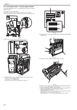
3) Open the front cover and put the door switch tool into the door switch [1].
F-5-115
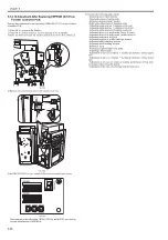
4) Remove the screw [2] to remove the switch cover [1].
F-5-116
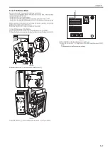
5) Set DIP SW382 [1] on the switch PCB as shown in the figure below.
F-5-117
Press buttons in the order from SW385, SW384, and SW383 once each to
execute initialization of EEPROM.
6) Execute the following adjustments:
- Adjusting sensor light intensity
- Speed adjustment of swing guide
- Adjusting alignment plate position
- Right angle adjustment of alignment plate
- Adjusting staple position (1-stapling at the rear)
- Adjusting staple position (1-stapling at the front)
- Adjusting staple position (2-stapling positions)
- Adjusting delivery of staple stack (lower delivery)
- Adjusting delivery of staple stack (saddle delivery)
- Adjusting position of feed belt
- Adjusting position of saddle lead edge stopper
- Adjusting saddle stitching position
- Adjusting saddle folding position
- Bufferless mode
- Adjusting height of staple inlet guide
- Adjusting paddle height
- Adjustment in the case of failure in stacking performance of tray (upper
curl)
- Adjustment in the case of failure in stacking performance of tray (lower
curl)
- Adjustment in the case of failure in stacking performance of tray (run-
on of paper when using thin paper)
- Adjustment in the case of canceling limit for tray stack
[1]
[2]
[1]
SW382
SW381
SW383
(-)
(+)
ENTER
SW384 SW385
DSP381
Summary of Contents for Saddle Finisher-AF2
Page 1: ...SERVICE MANUAL Saddle Finisher AF2 MARCH 6 2009...
Page 2: ......
Page 6: ......
Page 12: ...Contents...
Page 13: ...Chapter 1 Specifications...
Page 14: ......
Page 16: ......
Page 22: ......
Page 23: ...Chapter 2 Installation...
Page 24: ......
Page 26: ......
Page 55: ...Chapter 3 Functions...
Page 56: ......
Page 58: ......
Page 104: ...Chapter 3 3 46...
Page 105: ...Chapter 4 Parts Replacement Procedure...
Page 106: ......
Page 110: ......
Page 157: ...Chapter 4 4 47 F 4 213 3 2 1...
Page 158: ......
Page 159: ...Chapter 5 Maintenance...
Page 160: ......
Page 209: ...Chapter 5 5 47 F 5 221 SW382 SW381 SW383 ENTER SW384 SW385 DSP381 1...
Page 218: ......
Page 219: ...Appendix...
Page 220: ......
Page 221: ...General Timing Chart General Circuit Diagram Finisher Sorter DeliveryTray Saddle Finisher AF2...
Page 222: ......
Page 224: ......
Page 225: ...Contents 1 General Circuit Diagram 1 Signal Names 1 General Circuit Diagram 9...
Page 226: ......
Page 243: ......
Page 244: ......


