
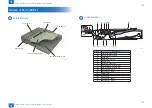


2
2
2-13
2-13
Technology > Basic Configuration (DADF) > Component Configuration > Outline of Electric Circuits
Technology > Basic Configuration (DADF) > Component Configuration > Outline of Electric Circuits
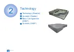
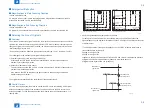
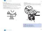
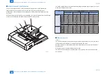
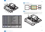
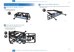
Basic Configuration (DADF)
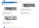
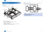
Component Configuration
■
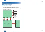
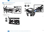
Outline of Electric Circuits
Electric circuits of this machine are controlled by the main controller PCB2. The main
controller PCB2 detect the input signals from sensors to output the signals that
drive DC loads such as motors, solenoids, clutches, and fans at the predetermined timings.
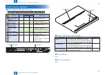
The ADF driver PCB does not have a memory area; data such as the data used in the service
mode is stored in main controller PCB2.
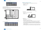
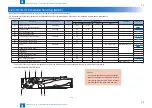
ADF driver PCB
Clutch
Reader relay PCB
J9
J11
Motor
Sensor
Solenoid
Fan
J10
J509
J503
J504
Main controller
PCB2
F-2-25